CN202177695U - Electric energy meter robot charge/discharge sucker apparatus - Google Patents
Electric energy meter robot charge/discharge sucker apparatus Download PDFInfo
- Publication number
- CN202177695U CN202177695U CN2011202631880U CN201120263188U CN202177695U CN 202177695 U CN202177695 U CN 202177695U CN 2011202631880 U CN2011202631880 U CN 2011202631880U CN 201120263188 U CN201120263188 U CN 201120263188U CN 202177695 U CN202177695 U CN 202177695U
- Authority
- CN
- China
- Prior art keywords
- electric energy
- energy meter
- buffer
- unloading
- suction cup
- Prior art date
- Legal status (The legal status is an assumption and is not a legal conclusion. Google has not performed a legal analysis and makes no representation as to the accuracy of the status listed.)
- Expired - Lifetime
Links
Images


Landscapes
- Manipulator (AREA)
Abstract
本实用新型所设计的一种电能表机器人上下料吸盘装置,解决了目前电能表上下料仍为人工操作,效率低下的技术问题。本实用新型包括固定板,其特征是所述的固定板一侧装有转换接口,固定板另一侧装有缓冲件,所述的缓冲件外侧连接一连接板,所述的连接板外侧装有海绵吸盘。本实用新型采用吸盘式吸住电能表进行位移,相比夹具夹持电能表,海绵吸盘更为可靠,对电能表位置精度要求低,更容易握持住电能表,搬运要求低,可加快搬运速度,提高移载效率;缓冲件可在海绵吸盘吸取电能表时进行缓冲,保护电能表不受挤压损伤。
The utility model designs a robot loading and unloading sucker device for an electric energy meter, which solves the technical problem that the loading and unloading of the electric energy meter is still manually operated and the efficiency is low. The utility model includes a fixed plate, which is characterized in that one side of the fixed plate is equipped with a conversion interface, the other side of the fixed plate is equipped with a buffer, the outer side of the buffer is connected to a connecting plate, and the outer side of the connecting plate is installed There are sponge suction cups. The utility model adopts the suction cup type to hold the electric energy meter for displacement. Compared with the electric energy meter clamped by the clamp, the sponge suction cup is more reliable, has lower requirements on the position accuracy of the electric energy meter, is easier to hold the electric energy meter, has low handling requirements, and can speed up the handling The speed improves the transfer efficiency; the buffer part can buffer when the sponge suction cup absorbs the electric energy meter, so as to protect the electric energy meter from being squeezed and damaged.
Description
技术领域 technical field
本实用新型涉及吸盘装置,尤其是一种电能表机器人上下料吸盘装置。The utility model relates to a suction cup device, in particular to a suction cup device for feeding and unloading a robot for an electric energy meter.
背景技术 Background technique
为了电能表的检定方便,一般将电能表从表箱移至工装板上进行检定,检定等工序完毕后再将电能表从工装板移回至表箱,当前上述移载工作仍为人工操作,这种工作方式劳动强度大、工作效率低,已不适应于工业自动化的生产需要,为实现全自动检定,需研发出一种满足电能表上述移载动作的取放装置。For the convenience of the verification of the electric energy meter, the electric energy meter is generally moved from the meter box to the tooling board for verification. After the verification and other procedures are completed, the electric energy meter is moved back from the tooling board to the meter box. At present, the above-mentioned transfer work is still manual operation. This working method is labor-intensive and low-efficiency, and is no longer suitable for the production needs of industrial automation. In order to realize automatic verification, it is necessary to develop a pick-and-place device that meets the above-mentioned transfer action of the electric energy meter.
实用新型内容 Utility model content
本实用新型的目的是为了解决上述现有技术的不足而提供一种电能表机器人上下料吸盘装置,实现电能表在表箱与工装板间的机械化移载,移载可靠,快捷,且不对电能表表面造成损伤。The purpose of this utility model is to provide a robot loading and unloading suction cup device for an electric energy meter to solve the above-mentioned deficiencies in the prior art, so as to realize the mechanized transfer of the electric energy meter between the meter box and the tooling plate, and the transfer is reliable and fast, and does not affect the electric energy. damage to the surface.
为了达到上述目的,本实用新型所设计的一种电能表机器人上下料吸盘装置,包括固定板,其特征是所述的固定板一侧装有转换接口,固定板另一侧装有缓冲件,所述的缓冲件外侧连接一连接板,所述的连接板外侧装有海绵吸盘。在搬运电能表时,海绵吸盘吸住电能表进行位移,相比夹具夹持电能表,海绵吸盘更为可靠,对电能表位置精度要求低,更容易握持住电能表,搬运要求低,可加快搬运速度,提高移载效率;缓冲件可在海绵吸盘吸取电能表时进行缓冲,保护电能表不受挤压损伤。In order to achieve the above-mentioned purpose, a kind of electric energy meter robot loading and unloading sucker device designed by the utility model includes a fixed plate, which is characterized in that one side of the fixed plate is equipped with a conversion interface, and the other side of the fixed plate is equipped with a buffer. The outer side of the buffer member is connected with a connecting plate, and the outer side of the connecting plate is equipped with a sponge suction cup. When transporting the electric energy meter, the sponge suction cup absorbs the electric energy meter for displacement. Compared with the clamp to hold the electric energy meter, the sponge suction cup is more reliable, has lower requirements on the position accuracy of the electric energy meter, and is easier to hold the electric energy meter. Accelerate the handling speed and improve the transfer efficiency; the cushioning parts can buffer the electric energy meter when the sponge suction cup absorbs it, protecting the electric energy meter from being squeezed and damaged.
作为上述结构的进一步完善和补充,本实用新型还包含以下附加技术特征或这些特征的任意组合:As a further improvement and supplement to the above structure, the utility model also includes the following additional technical features or any combination of these features:
所述的缓冲件由导向柱和导向轴承组成,所述的导向轴承设置在固定板上,所述的导向柱一端连接在导向轴承上,导向柱另一端固接连接板,电能表搬运受挤压时,导向柱伸入导向轴承,起到缓冲作用。The buffer is composed of a guide column and a guide bearing. The guide bearing is arranged on a fixed plate. One end of the guide column is connected to the guide bearing, and the other end of the guide column is fixedly connected to the connecting plate. When pressing, the guide column extends into the guide bearing to play a buffering role.
所述连接板上表面的两端分别连接一缓冲件,提升整体稳定性。The two ends of the upper surface of the connecting plate are respectively connected with a buffer piece, so as to improve the overall stability.
所述的连接板下表面上装有多个海绵吸盘,所述的海绵吸盘呈并排设置,可同时抓取多个电能表,进一步提高移载效率。The lower surface of the connecting plate is equipped with a plurality of sponge suction cups, and the sponge suction cups are arranged side by side, which can simultaneously grasp a plurality of electric energy meters, further improving the transfer efficiency.
本实用新型得到的一种电能表机器人上下料吸盘装置,采用吸盘式吸住电能表进行位移,相比夹具夹持电能表,海绵吸盘更为可靠,对电能表位置精度要求低,更容易握持住电能表,搬运要求低,可加快搬运速度,提高移载效率;缓冲件可在海绵吸盘吸取电能表时进行缓冲,保护电能表不受挤压损伤。The utility model obtains a suction cup device for loading and unloading the electric energy meter robot, which adopts the suction cup type to hold the electric energy meter for displacement. Compared with clamping the electric energy meter, the sponge suction cup is more reliable, has lower requirements on the position accuracy of the electric energy meter, and is easier to hold Holding the electric energy meter, the handling requirements are low, the handling speed can be accelerated, and the transfer efficiency can be improved; the buffer can buffer the electric energy meter when the sponge suction cup absorbs it, and protect the electric energy meter from being squeezed and damaged.
附图说明 Description of drawings
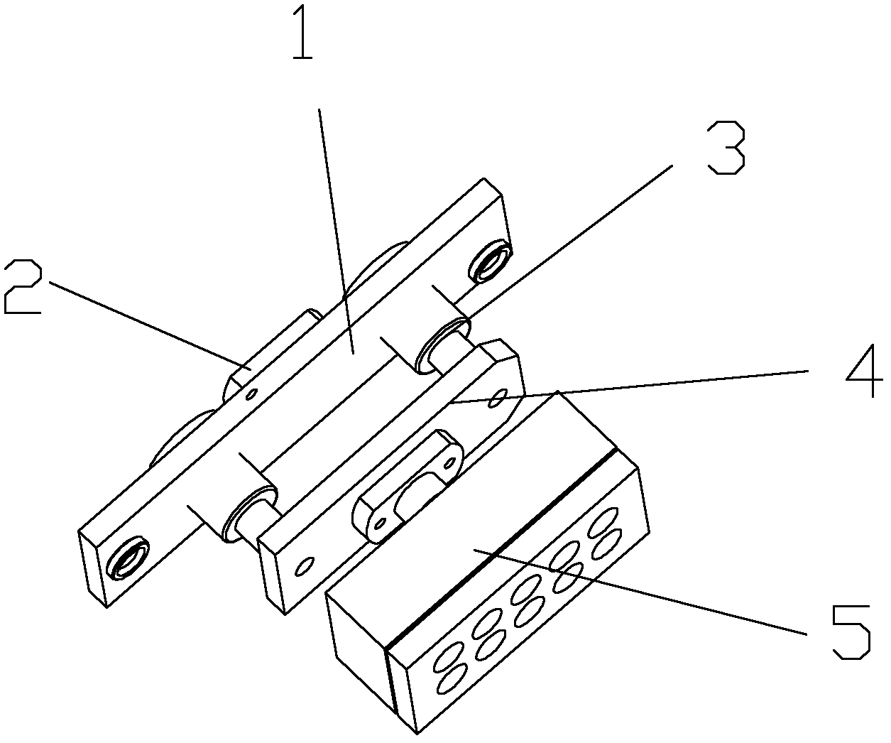
图1是本实用新型的结构示意图;Fig. 1 is a structural representation of the utility model;
图2是本实用新型爆炸结构示意图;Fig. 2 is a schematic diagram of the explosion structure of the utility model;
图3是本实用新型另一结构示意图。Fig. 3 is a schematic diagram of another structure of the utility model.
图中:1-固定板、2-转换接口、3-缓冲件、4-连接板、5-海绵吸盘、6-导向柱、7-导向轴承。In the figure: 1-fixing plate, 2-converting interface, 3-bumper, 4-connecting plate, 5-sponge suction cup, 6-guiding column, 7-guiding bearing.
具体实施方式 Detailed ways
下面通过实施例结合附图对本实用新型作进一步的描述。Below by embodiment in conjunction with accompanying drawing, the utility model is further described.
如图1、图2所示,本实施例描述的一种电能表机器人上下料吸盘装置,包括固定板1,所述的固定板1一侧装有转换接口2,固定板1另一侧装有缓冲件3,所述的缓冲件3外侧连接一连接板4,所述的连接板4外侧装有海绵吸盘5。所述的缓冲件3由导向柱6和导向轴承7组成,所述的导向轴承7设置在固定板1上,所述的导向柱6一端连接在导向轴承7上,导向柱6另一端固接连接板4。所述连接板4上表面的两端分别连接一缓冲件3。As shown in Fig. 1 and Fig. 2, a kind of electric energy meter robot loading and unloading sucker device described in this embodiment includes a
为进一步提高电能表移载效率,所述的连接板4下表面上可装有多个海绵吸盘5,所述的海绵吸盘5呈并排设置。如图3所示,连接板4下表面装有三个呈并排设置的海绵吸盘5。In order to further improve the transfer efficiency of the electric energy meter, a plurality of
Claims (4)
Priority Applications (1)
| Application Number | Priority Date | Filing Date | Title |
|---|---|---|---|
| CN2011202631880U CN202177695U (en) | 2011-07-22 | 2011-07-22 | Electric energy meter robot charge/discharge sucker apparatus |
Applications Claiming Priority (1)
| Application Number | Priority Date | Filing Date | Title |
|---|---|---|---|
| CN2011202631880U CN202177695U (en) | 2011-07-22 | 2011-07-22 | Electric energy meter robot charge/discharge sucker apparatus |
Publications (1)
| Publication Number | Publication Date |
|---|---|
| CN202177695U true CN202177695U (en) | 2012-03-28 |
Family
ID=45867568
Family Applications (1)
| Application Number | Title | Priority Date | Filing Date |
|---|---|---|---|
| CN2011202631880U Expired - Lifetime CN202177695U (en) | 2011-07-22 | 2011-07-22 | Electric energy meter robot charge/discharge sucker apparatus |
Country Status (1)
| Country | Link |
|---|---|
| CN (1) | CN202177695U (en) |
Cited By (3)
| Publication number | Priority date | Publication date | Assignee | Title |
|---|---|---|---|---|
| CN104924296A (en) * | 2015-06-26 | 2015-09-23 | 国家电网公司 | Electric energy meter gripping device |
| CN105729302A (en) * | 2016-03-21 | 2016-07-06 | 中国人民解放军第三军医大学第一附属医院 | Clamp for preparing dental micro-tensile specimen and process for clamp |
| CN108020810A (en) * | 2017-12-29 | 2018-05-11 | 国网新疆电力有限公司电力科学研究院 | Electric energy meter detects mobile device |
-
2011
- 2011-07-22 CN CN2011202631880U patent/CN202177695U/en not_active Expired - Lifetime
Cited By (4)
| Publication number | Priority date | Publication date | Assignee | Title |
|---|---|---|---|---|
| CN104924296A (en) * | 2015-06-26 | 2015-09-23 | 国家电网公司 | Electric energy meter gripping device |
| CN105729302A (en) * | 2016-03-21 | 2016-07-06 | 中国人民解放军第三军医大学第一附属医院 | Clamp for preparing dental micro-tensile specimen and process for clamp |
| CN105729302B (en) * | 2016-03-21 | 2018-11-20 | 中国人民解放军第三军医大学第一附属医院 | It is used to prepare the fixture and technique of dentistry micro-stretching test specimen |
| CN108020810A (en) * | 2017-12-29 | 2018-05-11 | 国网新疆电力有限公司电力科学研究院 | Electric energy meter detects mobile device |
Similar Documents
| Publication | Publication Date | Title |
|---|---|---|
| CN202174585U (en) | Robot loading and unloading device for electric energy meter | |
| CN103846914B (en) | A kind of new type fittings Handling device | |
| CN102183739B (en) | Device for moving electric energy meter between meter case and multi-epitope tooling board | |
| CN102874595A (en) | Combined type material picking hand device | |
| CN203767634U (en) | Robot palletizer box type cargo gripper | |
| CN205045491U (en) | A substrate auto -control handling system for physical vapor deposition coating film | |
| CN102642150A (en) | Pole piece feeding device | |
| CN205177946U (en) | Mass flow piece feeding system | |
| CN206123690U (en) | Grab table device based on sucking disc is gathered | |
| CN202828939U (en) | Combined material taking hand device | |
| CN206126283U (en) | Table device is grabbed to three -phase tong | |
| CN205674220U (en) | A kind of sucker gripper | |
| CN206437637U (en) | A kind of floating stack device | |
| CN202037602U (en) | An electric energy meter handling manipulator suitable for single-meter tooling board | |
| CN204108537U (en) | A BLU feeding manipulator | |
| CN102152304B (en) | Electric energy meter carrying manipulator suitable for single-meter position tooling plate | |
| CN206590574U (en) | A kind of handgrip for capturing lithium battery | |
| CN104227276A (en) | A BLU feeding manipulator | |
| CN204341825U (en) | Cond clamping tooling and cond clamping device | |
| CN203112120U (en) | Meter gripping manipulator of terminal electric-energy meters | |
| CN205343155U (en) | Servo tongs of electricity mandrel group | |
| CN211866229U (en) | A top cover feeding and shaping device | |
| CN204324375U (en) | Wrist-watch performing leak test tool | |
| CN203392478U (en) | Mechanism matching with manipulator to achieve automatic product taking and placing | |
| CN207272000U (en) | A small independent stamping transfer manipulator |
Legal Events
| Date | Code | Title | Description |
|---|---|---|---|
| C14 | Grant of patent or utility model | ||
| GR01 | Patent grant | ||
| CB03 | Change of inventor or designer information | ||
| CB03 | Change of inventor or designer information |
Inventor after: Xiao Tao Inventor after: Huang Jinjuan Inventor after: Yan Huajiang Inventor after: Wu Jian Inventor after: Xu Yongjin Inventor after: Dong Qiang Inventor after: Ding Rongrong Inventor before: Xiao Tao Inventor before: Yan Huajiang Inventor before: Wu Jian Inventor before: Xu Yongjin Inventor before: Dong Qiang Inventor before: Ding Rongrong |
|
| CP01 | Change in the name or title of a patent holder | ||
| CP01 | Change in the name or title of a patent holder |
Address after: 310007 Huanglong Road, Hangzhou, Zhejiang, No. 8, No. Patentee after: State Grid Zhejiang Electric Power Company Address before: 310007 Huanglong Road, Hangzhou, Zhejiang, No. 8, No. Patentee before: Zhejiang Electric Power Company |
|
| CX01 | Expiry of patent term | ||
| CX01 | Expiry of patent term |
Granted publication date: 20120328 |