CN202176160U - Boosting handle and refrigerating device - Google Patents
Boosting handle and refrigerating device Download PDFInfo
- Publication number
- CN202176160U CN202176160U CN 201120265705 CN201120265705U CN202176160U CN 202176160 U CN202176160 U CN 202176160U CN 201120265705 CN201120265705 CN 201120265705 CN 201120265705 U CN201120265705 U CN 201120265705U CN 202176160 U CN202176160 U CN 202176160U
- Authority
- CN
- China
- Prior art keywords
- handle
- push rod
- power
- pedestal
- door body
- Prior art date
- Legal status (The legal status is an assumption and is not a legal conclusion. Google has not performed a legal analysis and makes no representation as to the accuracy of the status listed.)
- Expired - Fee Related
Links
Images

Landscapes
- Refrigerator Housings (AREA)
Abstract
Description
技术领域 technical field
本实用新型涉及制冷装置,尤其涉及一种助力把手及制冷设备。 The utility model relates to a refrigeration device, in particular to a power-assisted handle and refrigeration equipment.
背景技术 Background technique
目前,制冷设备(例如冰箱或立式冷柜)是人们的日常生活中常用的家用电器。制冷设备的门体上通常固定有把手,从而方便用户手拉把手以打开门体。由于在制冷设备的门体闭合后,制冷设备内进行制冷温度降低造成压强降低,门体内外形成压差,导致用户直接拉动门体上的把手开门困难。 At present, refrigeration equipment (such as a refrigerator or an upright freezer) is a household appliance commonly used in people's daily life. A handle is usually fixed on the door body of the refrigeration equipment, so that it is convenient for the user to pull the handle to open the door body. After the door body of the refrigeration equipment is closed, the cooling temperature in the refrigeration equipment decreases, resulting in a decrease in pressure, and a pressure difference is formed inside and outside the door, making it difficult for the user to directly pull the handle on the door body to open the door.
发明内容 Contents of the invention
本实用新型所要解决的技术问题是:提供一种助力把手及制冷设备,解决现有技术中用户直接拉动制冷设备门体上的把手开门困难的缺陷,实现通过助力把手方便用户打开门体。 The technical problem to be solved by the utility model is to provide a power-assisted handle and refrigeration equipment, which solves the defect in the prior art that it is difficult for the user to directly pull the handle on the door of the refrigeration equipment to open the door, and realizes the convenience for the user to open the door through the power-assisted handle.
本实用新型提供的技术方案是,一种助力把手,包括:安装座、把手、推杆和复位弹簧,所述推杆与所述安装座呈滑动配合,所述安装座和所述推杆之间有复位弹簧;安装座上铰接有所述把手构成省力杠杆,所述把手的阻力臂抵靠在所述推杆的一端构成传动机构。 The technical solution provided by the utility model is a power-assisted handle, including: a mounting seat, a handle, a push rod and a return spring, the push rod is in sliding fit with the mounting seat, and the connection between the mounting seat and the push rod There is a return spring between them; the handle is hinged on the mounting base to form a labor-saving lever, and the resistance arm of the handle abuts against one end of the push rod to form a transmission mechanism.
本实用新型提供的助力把手,通过转动把手可以驱动推杆在安装座中滑动,当用户需要打开制冷设备的门体时, 用户拉动把手后,把手将抵靠在推杆的一端部上使推杆相对于安装座滑动,此时推杆的另一端部将抵靠在制冷设备上,根据杠杆原理使门体局部受较大的力,实现通过助力把手方便用户打开门体。 The power-assisted handle provided by the utility model can drive the push rod to slide in the mounting seat by turning the handle. When the user needs to open the door body of the refrigeration equipment, after the user pulls the handle, the handle will lean against one end of the push rod to make the push rod The rod slides relative to the mounting seat. At this time, the other end of the push rod will lean against the refrigeration equipment. According to the principle of leverage, the door body is partially subjected to a relatively large force, so that the user can easily open the door body through the power-assisted handle.
如上所述的助力把手,所述安装座包括盖板和基座,所述基座上设置有滑槽,所述把手铰接在所述基座上,所述推杆滑动设置在所述滑槽中,所述推杆设置有挡板,所述复位弹簧的一端抵靠在所述基座上,所述复位弹簧的另一端抵靠在所述挡板上,所述盖板固设在所述基座上,所述推杆位于所述基座和所述盖板之间。 As for the booster handle mentioned above, the mounting base includes a cover plate and a base, the base is provided with a chute, the handle is hinged on the base, and the push rod is slidably arranged on the chute Among them, the push rod is provided with a baffle, one end of the return spring abuts against the base, the other end of the return spring abuts against the baffle, and the cover is fixed on the On the base, the push rod is located between the base and the cover.
如上所述的助力把手,所述把手包括前盖和后盖,所述后盖开设有安装孔,所述后盖还设置有连接板,所述连接板位于所述安装孔的一侧,所述连接板开设有轴孔,所述前盖固设在所述后盖上,所述连接板位于所述前盖和所述后盖之间;所述基座设置有轴座,所述轴座穿在所述安装孔中,所述连接板通过转轴与所述轴座铰接在一起。 As for the booster handle as described above, the handle includes a front cover and a rear cover, the rear cover is provided with a mounting hole, and the rear cover is also provided with a connecting plate, the connecting plate is located on one side of the mounting hole, the The connecting plate is provided with a shaft hole, the front cover is fixed on the rear cover, and the connecting plate is located between the front cover and the rear cover; the base is provided with a shaft seat, and the shaft The seat passes through the mounting hole, and the connecting plate is hinged with the shaft seat through a rotating shaft.
如上所述的助力把手,所述后盖还设置有凸起结构,所述凸起结构位于所述安装孔的上方;当所述助力把手不受拉力时,所述凸起结构抵靠在所述基座上。 As for the booster handle mentioned above, the rear cover is also provided with a protruding structure, and the protruding structure is located above the installation hole; when the booster handle is not pulled, the protruding structure is against the on the base.
如上所述的助力把手,所述基座上还开设有多个固定孔。 As described above in the booster handle, a plurality of fixing holes are also opened on the base.
如上所述的助力把手,所述基座上还设置有复位弹簧固定柱,所述复位弹簧套在所述复位弹簧固定柱上。如上所述的助力把手,所述推杆远离所述把手的端部设置有缓冲垫。 As for the booster handle described above, the base is further provided with a return spring fixing post, and the return spring is sleeved on the return spring fixing post. According to the booster handle mentioned above, the end of the push rod away from the handle is provided with a buffer pad.
如上所述的助力把手,所述推杆靠近所述把手的端部设置有凹槽,所述前盖设置有支撑筋,所述支撑筋位于所述凹槽中。 According to the booster handle mentioned above, a groove is provided at the end of the push rod close to the handle, and a support rib is provided on the front cover, and the support rib is located in the groove.
本实用新型提供的技术方案是,一种制冷设备,包括制冷设备主体和门体,所述门体铰接在所述制冷设备门体上,还包括如上所述的助力把手,所述助力把手固设在所述门体上,所述助力把手的推杆朝向所述制冷设备主体。 The technical solution provided by the utility model is a refrigeration equipment, including a refrigeration equipment main body and a door body, the door body is hinged on the refrigeration equipment door body, and also includes the above-mentioned power-assisted handle, and the power-assisted handle is fixed It is arranged on the door body, and the push rod of the booster handle faces the main body of the refrigeration equipment.
本实用新型提供的制冷设备,通过转动把手可以驱动推杆在安装座中滑动,当用户需要打开制冷设备的门体时, 用户拉动把手后,把手将抵靠在推杆的一端部上使推杆相对于安装座滑动,此时推杆的另一端部将抵靠在制冷设备上,根据杠杆原理使门体局部受较大的力,实现通过助力把手方便用户打开门体。 The refrigeration equipment provided by the utility model can drive the push rod to slide in the installation seat by turning the handle. When the user needs to open the door body of the refrigeration equipment, after the user pulls the handle, the handle will lean against one end of the push rod to make the push rod The rod slides relative to the mounting seat. At this time, the other end of the push rod will lean against the refrigeration equipment. According to the principle of leverage, the door body is partially subjected to a relatively large force, so that the user can easily open the door body through the power-assisted handle.
附图说明 Description of drawings
为了更清楚地说明本实用新型实施例或现有技术中的技术方案,下面将对实施例或现有技术描述中所需要使用的附图作一简单地介绍,显而易见地,下面描述中的附图是本实用新型的一些实施例,对于本领域普通技术人员来讲,在不付出创造性劳动性的前提下,还可以根据这些附图获得其他的附图。 In order to more clearly illustrate the technical solutions in the embodiments of the present invention or the prior art, the following will briefly introduce the accompanying drawings that need to be used in the description of the embodiments or the prior art. Obviously, the appended drawings in the following description The drawings are some embodiments of the utility model, and those skilled in the art can also obtain other drawings according to these drawings on the premise of not paying creative labor.
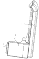
图1为本实用新型助力把手实施例的结构示意图; Fig. 1 is a schematic structural view of an embodiment of the power-assisted handle of the present invention;
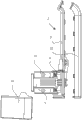
图2为本实用新型助力把手实施例的爆炸图; Fig. 2 is an exploded view of an embodiment of the power-assisted handle of the present invention;
图3为本实用新型助力把手实施例中基座的结构示意图; Fig. 3 is a schematic structural view of the base in the embodiment of the power-assisted handle of the present invention;
图4为本实用新型助力把手实施例中把手的结构示意图; Fig. 4 is a structural schematic diagram of the handle in the embodiment of the power-assisted handle of the present invention;
图5为本实用新型助力把手实施例中推杆的结构示意图。 Fig. 5 is a structural schematic diagram of the push rod in the embodiment of the power-assisted handle of the present invention.
具体实施方式 Detailed ways
为使本实用新型实施例的目的、技术方案和优点更加清楚,下面将结合本实用新型实施例中的附图,对本实用新型实施例中的技术方案进行清楚、完整地描述,显然,所描述的实施例是本实用新型一部分实施例,而不是全部的实施例。基于本实用新型中的实施例,本领域普通技术人员在没有作出创造性劳动前提下所获得的所有其他实施例,都属于本实用新型保护的范围。 In order to make the purpose, technical solutions and advantages of the embodiments of the utility model more clear, the technical solutions in the embodiments of the utility model will be clearly and completely described below in conjunction with the accompanying drawings in the embodiments of the utility model. Obviously, the described The embodiments are some embodiments of the present utility model, but not all embodiments. Based on the embodiments of the present utility model, all other embodiments obtained by persons of ordinary skill in the art without making creative efforts belong to the scope of protection of the present utility model.
图1为本实用新型助力把手实施例的结构示意图,图2为本实用新型助力把手实施例的爆炸图,图3为本实用新型助力把手实施例中基座的结构示意图,图4为本实用新型助力把手实施例中把手的结构示意图,图5为本实用新型助力把手实施例中推杆的结构示意图。如图1-图5所示,本实施例助力把手,包括:安装座1、把手2、推杆3和复位弹簧4,
Fig. 1 is a schematic structural view of an embodiment of the power-assist handle of the present invention, Fig. 2 is an exploded view of an embodiment of the power-assist handle of the present invention, Fig. 3 is a schematic structural view of the base in an embodiment of the power-assist handle of the present invention, and Fig. 4 is a schematic diagram of the base of the embodiment of the present utility model The structure diagram of the handle in the embodiment of the new power-assisted handle, and Fig. 5 is the structure diagram of the push rod in the embodiment of the power-assisted handle of the present invention. As shown in Fig. 1-Fig. 5, the booster handle of this embodiment includes: mounting base 1,
推杆3与安装座1呈滑动配合,安装座1和推杆3之间有复位弹簧4;安装座1上铰接有把手2构成省力杠杆,把手2的阻力臂抵靠在推杆3的一端构成传动机构。 The push rod 3 is in a sliding fit with the mounting base 1, and there is a return spring 4 between the mounting base 1 and the push rod 3; constitute the transmission mechanism.
具体而言,本实施例助力把手的安装座1上铰接有把手2,通过转动把手2可以驱动推杆3相对于安装座1滑动,并且在把手2不受力的情况下,复位弹簧4将带动推杆3复位。装配有本实施例助力把手的制冷设备,可以将安装座1固定在制冷设备的门体上并将推杆3对着制冷设备的主体,当需要打开制冷设备的门体时,用户通过转动把手2以驱动推杆3抵靠在制冷设备主体上,转动中的把手2利用杠杆原理能够使用户施加较小的力,便可以轻松方便的将制冷设备的门体打开。
Specifically, a
其中,本实施例中的安装座1可以包括盖板10和基座11,基座11上设置有滑槽111,把手2铰接在基座11上,推杆3滑动设置在滑槽111中,推杆3设置有挡板31,复位弹簧4的一端抵靠在基座11上,复位弹簧4的另一端抵靠在挡板31上,盖板10固设在基座11上,推杆3位于基座11和盖板10之间。具体的,推杆3能够在滑槽111中滑动,推杆3的挡板31与基座11之间设置有复位弹簧4,从而通过复位弹簧4实现推杆3复位。优选的,为了方便的将本实施例助力把手装配到制冷设备上,本实施例基座11上可以还开设有多个固定孔113。通过螺钉穿过固定孔113与制冷设备的门体螺接,便可以将本实施例助力把手方便的固定装配到制冷设备上。另外,为了防止在压缩复位弹簧4过程中,复位弹簧4发生移位,本实施例中的基座11上可以还设置有复位弹簧固定柱114,复位弹簧4套在复位弹簧固定柱114上。
Wherein, the mounting seat 1 in this embodiment may include a
另外,本实施例中的把手2可以包括前盖22和后盖21,后盖21开设有安装孔211,后盖21还设置有连接板212,连接板212位于安装孔211的一侧,连接板212开设有轴孔2121,前盖22固设在后盖21上,连接板212位于前盖22和后盖21之间;基座11设置有轴座112,轴座112穿在安装孔211中,连接板212通过转轴(未图示)与轴座112铰接在一起。具体而言,本实施例中的把手2的后盖21上开设有安装孔211,基座11上的轴座112能够插入到安装孔211中并与后盖21上的连接板212通过转轴连接在一起,实现把手2能够相对于安装座1转动。优选的,为了限定把手2在不受力时的位置,本实施例中的后盖21可以还设置有凸起结构213,凸起结构213位于安装孔211的上方;当本实施例助力把手不受拉力时,凸起结构213抵靠在基座11上,通过凸起结构213实现对不受外力状态下的把手2进行定位,使把手2能够平行于制冷设备的门体。其中,为了避免推杆在挤压制冷设备时,将制冷设备损坏,本实施例中的推杆3远离把手2的端部可以设置有缓冲垫32。另外,为了使把手2能够可靠的推动推杆3,本实施例中的推杆3靠近把手2的端部设置有凹槽33,前盖22设置有支撑筋221,支撑筋221位于凹槽33中。
In addition, the
本实施例助力把手,通过转动把手可以驱动推杆在安装座中滑动,当用户需要打开制冷设备的门体时, 用户拉动把手后,把手将抵靠在推杆的一端部上使推杆相对于安装座滑动,此时推杆的另一端部将抵靠在制冷设备上,根据杠杆原理使门体局部受较大的力,实现通过助力把手方便用户打开门体。 The power-assisted handle of this embodiment can drive the push rod to slide in the mounting seat by turning the handle. When the user needs to open the door of the refrigeration equipment, after the user pulls the handle, the handle will lean against one end of the push rod so that the push rod is opposite to each other. Slide on the mounting seat, at this time the other end of the push rod will be against the refrigeration equipment, and according to the principle of leverage, the door body will be partially subjected to a relatively large force, so that the user can easily open the door body through the power-assisted handle.
本实用新型还提供一种制冷设备,包括制冷设备主体和门体,门体铰接在制冷设备门体上,还包括助力把手,助力把手固设在门体上,助力把手的推杆朝向制冷设备主体。 The utility model also provides a refrigerating device, which includes a main body of the refrigerating device and a door body, the door body is hinged on the door body of the refrigerating device, and a power-assisted handle is fixed on the door body, and the push rod of the power-assisted handle faces the refrigerating device main body.
具体而言,本实施例中的助力把手可以采用本实用新型助力把手实施例中的助力把手,其具体结构可以参见本实用新型助力把手实施例以及附图1-图5的记载,在此不再赘述。 Specifically, the booster handle in this embodiment can adopt the booster handle in the embodiment of the utility model booster handle, and its specific structure can refer to the description of the utility model booster handle embodiment and accompanying drawings 1-5. Let me repeat.
本实施例制冷设备,通过转动把手可以驱动推杆在安装座中滑动,当用户需要打开制冷设备的门体时, 用户拉动把手后,把手将抵靠在推杆的一端部上使推杆相对于安装座滑动,此时推杆的另一端部将抵靠在制冷设备上,根据杠杆原理使门体局部受较大的力,实现通过助力把手方便用户打开门体。 The refrigeration equipment of this embodiment can drive the push rod to slide in the mounting seat by turning the handle. When the user needs to open the door of the refrigeration equipment, after the user pulls the handle, the handle will lean against one end of the push rod so that the push rod is opposite to each other. Slide on the mounting seat, at this time the other end of the push rod will be against the refrigeration equipment, and according to the principle of leverage, the door body will be partially subjected to a relatively large force, so that the user can easily open the door body through the power-assisted handle.
最后应说明的是:以上实施例仅用以说明本实用新型的技术方案,而非对其限制;尽管参照前述实施例对本实用新型进行了详细的说明,本领域的普通技术人员应当理解:其依然可以对前述各实施例所记载的技术方案进行修改,或者对其中部分技术特征进行等同替换;而这些修改或者替换,并不使相应技术方案的本质脱离本实用新型各实施例技术方案的精神和范围。 Finally, it should be noted that: the above embodiments are only used to illustrate the technical solutions of the present utility model, and are not intended to limit it; although the utility model has been described in detail with reference to the foregoing embodiments, those of ordinary skill in the art should understand that: It is still possible to modify the technical solutions recorded in the foregoing embodiments, or perform equivalent replacements for some of the technical features; and these modifications or replacements do not make the essence of the corresponding technical solutions deviate from the spirit of the technical solutions of the various embodiments of the present invention. and range.
Claims (9)
Priority Applications (1)
| Application Number | Priority Date | Filing Date | Title |
|---|---|---|---|
| CN 201120265705 CN202176160U (en) | 2011-07-26 | 2011-07-26 | Boosting handle and refrigerating device |
Applications Claiming Priority (1)
| Application Number | Priority Date | Filing Date | Title |
|---|---|---|---|
| CN 201120265705 CN202176160U (en) | 2011-07-26 | 2011-07-26 | Boosting handle and refrigerating device |
Publications (1)
| Publication Number | Publication Date |
|---|---|
| CN202176160U true CN202176160U (en) | 2012-03-28 |
Family
ID=45866045
Family Applications (1)
| Application Number | Title | Priority Date | Filing Date |
|---|---|---|---|
| CN 201120265705 Expired - Fee Related CN202176160U (en) | 2011-07-26 | 2011-07-26 | Boosting handle and refrigerating device |
Country Status (1)
| Country | Link |
|---|---|
| CN (1) | CN202176160U (en) |
Cited By (3)
| Publication number | Priority date | Publication date | Assignee | Title |
|---|---|---|---|---|
| CN105627661A (en) * | 2016-03-01 | 2016-06-01 | 仝达机电工业(惠州)有限公司 | Automatic door and drawer opening device used for refrigerator |
| CN108756461A (en) * | 2018-06-06 | 2018-11-06 | 青岛海尔特种电冰柜有限公司 | Booster door handles component and refrigeration equipment |
| CN111648654A (en) * | 2020-04-20 | 2020-09-11 | 青岛海尔特种电冰柜有限公司 | A door body and refrigeration equipment |
-
2011
- 2011-07-26 CN CN 201120265705 patent/CN202176160U/en not_active Expired - Fee Related
Cited By (6)
| Publication number | Priority date | Publication date | Assignee | Title |
|---|---|---|---|---|
| CN105627661A (en) * | 2016-03-01 | 2016-06-01 | 仝达机电工业(惠州)有限公司 | Automatic door and drawer opening device used for refrigerator |
| CN105627661B (en) * | 2016-03-01 | 2018-04-03 | 仝达机电工业(惠州)有限公司 | A kind of automatic door opening for refrigerator, open drawer |
| CN108756461A (en) * | 2018-06-06 | 2018-11-06 | 青岛海尔特种电冰柜有限公司 | Booster door handles component and refrigeration equipment |
| CN108756461B (en) * | 2018-06-06 | 2022-05-20 | 青岛海尔特种电冰柜有限公司 | Power-assisted door handle assembly and refrigeration equipment |
| CN111648654A (en) * | 2020-04-20 | 2020-09-11 | 青岛海尔特种电冰柜有限公司 | A door body and refrigeration equipment |
| CN111648654B (en) * | 2020-04-20 | 2022-10-25 | 青岛海尔特种电冰柜有限公司 | Door body and refrigeration equipment |
Similar Documents
| Publication | Publication Date | Title |
|---|---|---|
| CN107246184A (en) | Concealed booster door handles component and refrigeration plant | |
| CN203412364U (en) | Power-assisted door handle and refrigeration equipment | |
| CN101235692A (en) | A door hinge device | |
| WO2015027515A1 (en) | Hinge | |
| CN201297079Y (en) | Door stopper used on fast moving objects | |
| CN208232954U (en) | Portable electrical bracket quick disassembly structure | |
| CN203729671U (en) | Assistance handle and refrigeration plant | |
| CN211593532U (en) | A quick detachable thermal insulation cover | |
| CN206368611U (en) | Power-assisted handle component and refrigeration plant | |
| CN206158413U (en) | Multi -angle door fixing device | |
| CN201653046U (en) | A resettable refrigerator handle | |
| CN112302421A (en) | Booster handle and its refrigerator | |
| CN215187704U (en) | Rack for communication transmission equipment | |
| CN201628440U (en) | Refrigerator door opening device | |
| CN201590004U (en) | a laptop | |
| CN208155821U (en) | A kind of high temperature aging test box | |
| CN205536826U (en) | Door for refrigeration device and refrigeration device | |
| CN208382693U (en) | A kind of handle for refrigerator door component and refrigerator | |
| CN211138889U (en) | Mechanical flower | |
| CN210930272U (en) | Wardrobe with shoe storage space | |
| CN207332488U (en) | Concealed booster door handles component and refrigeration plant | |
| CN214986952U (en) | A low-loss fruit refrigerator | |
| CN212249625U (en) | Hovering door body connection structure of a disinfection cabinet | |
| CN201338255Y (en) | Light source dismounting device | |
| CN204230182U (en) | Torch integrated circuit breaker stored energy mechanism |
Legal Events
| Date | Code | Title | Description |
|---|---|---|---|
| C14 | Grant of patent or utility model | ||
| GR01 | Patent grant | ||
| CF01 | Termination of patent right due to non-payment of annual fee |
Granted publication date: 20120328 Termination date: 20200726 |
|
| CF01 | Termination of patent right due to non-payment of annual fee |