CN202170230U - Rope winding device - Google Patents
Rope winding device Download PDFInfo
- Publication number
- CN202170230U CN202170230U CN2011202435599U CN201120243559U CN202170230U CN 202170230 U CN202170230 U CN 202170230U CN 2011202435599 U CN2011202435599 U CN 2011202435599U CN 201120243559 U CN201120243559 U CN 201120243559U CN 202170230 U CN202170230 U CN 202170230U
- Authority
- CN
- China
- Prior art keywords
- wheel shaft
- wiring device
- wiring
- around
- bus cable
- Prior art date
- Legal status (The legal status is an assumption and is not a legal conclusion. Google has not performed a legal analysis and makes no representation as to the accuracy of the status listed.)
- Expired - Fee Related
Links
Images
Abstract
The utility model discloses a rope winding device, comprising a rotary winding wheel spindle on a position with a central shaft of the rope winding device, winding wheel plates fixed at both ends of the winding wheel spindle, a fixing rod parallel to the winding wheel spindle, and support plates fixed at both ends of the fixing rod, wherein a drawstring for hoisting a flag is wound on the winding wheel spindle; a movable wire arranging device with holes thereon is further positioned on the rope winding device; and the drawstring passes through the holes. The rope winding device of the utility model ensures the drawstring to wind on the rope winding device orderly by lead wires of the wire arranging device.
Description
Technical field
The utility model relates to the wiring device of flagraising usefulness, is specifically related to a kind of wiring device that has bus cable device.
Background technology
Generally be during flagraising under the accompaniment of national anthem, flag risen to the flagpole top, perhaps hoist a flag automatically and realize flagraising speed and temporal unification with motor with hand wiring device.The improvement of opposing connection rope device at present has a variety of; Pulley wiring in the past usually causes wiring not tight; Mostly adopt now, but hand or driven by motor rotate wiring rotation wiring around wheel shaft and usually can produce disorderly in, lap wound phenomenon, make flag flagraising traveling comfort receive very big influence around the wheel shaft wiring; When serious even can stuck stay cord, flagraising can't be moved.
The utility model content
The utility model purpose: the utility model provides a kind of ability with the neat wiring device around the home of the stay cord of flagraising usefulness in order to solve the deficiency of prior art.
The technical scheme that the utility model adopts: a kind of wiring device; Comprise be positioned at said wiring device center shaft position rotatable around wheel shaft, fixing and said around the wheel shaft two ends around wheel plate, with said around wheel shaft parallel fixed link and the stay bearing plate that is fixed on said fixed link two ends; The said stay cord that on wheel shaft, is wound with flagraising usefulness; Also be provided with movably bus cable device on the said wiring device, said bus cable device is provided with aperture, is installed with said stay cord in the said aperture.
As optimization, said bus cable device is with said parallel around wheel shaft, and bus cable device can move along said wiring device central axes, drives the stay cord wiring in the aperture, and wiring is more neat.
As optimization, saidly be provided with screw thread around wheel shaft, screw thread helps stay cord neatly to embed along screw thread.
As optimization, the said servomotor that on wheel shaft, is equipped with can be through the rotation of motor automatic guidance around wheel shaft.
As optimization, said servomotor can be realized the precise real-time control around wheel shaft wiring time and speed through the control of PLC control system through the PLC control system, thus the unification on control national flag build up time and the speed.
Principle of work: on the utility model wiring device bus cable device is housed; On wheel shaft, penetrate in the aperture of an end of stay cord from the bus cable device; Move the parallel back and forth of bus cable device when wheel shaft rotates; Drive wiring along with the screw thread on wheel shaft is parallel mobile around on one side on one side, make stay cord on wheel shaft, can very fitly curl up.
Beneficial effect: the utility model wiring device makes stay cord very fitly around the home on the wiring device through the lead-in wire of bus cable device.
Description of drawings
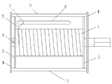
Accompanying drawing is the utility model wiring apparatus structure scheme drawing.
The specific embodiment
Shown in accompanying drawing, a kind of wiring device, comprise be positioned at said wiring device center shaft position rotatable around wheel shaft 1; Fixing and said around wheel shaft 1 two ends around wheel plate 2; Around wheel shaft 1 parallel fixed link 3 and the stay bearing plate 4 that is fixed on said fixed link 3 two ends, the said stay cord 5 that on wheel shaft 1, is wound with flagraising usefulness saidly is provided with screw thread around wheel shaft 1 with said; Also be provided with on the said wiring device with said around the parallel bus cable device 6 of wheel shaft 1; Said bus cable device 6 moves along said wiring device central axes, and said bus cable device 6 is provided with aperture 7, is installed with said stay cord 5 in the said aperture 7; The said servomotor 8 that on wheel shaft 1, is equipped with, said servomotor 8 is through the control of PLC control system.
Claims (5)
1. wiring device; Comprise that to be positioned at said wiring device center shaft position rotatable around wheel shaft (1); Fixing and said around wheel shaft (1) two ends around wheel plate (2); Around the parallel fixed link (3) of wheel shaft (1) be fixed on the stay bearing plate (4) at said fixed link (3) two ends, the said stay cord (5) that on wheel shaft (1), is wound with flagraising usefulness is characterized in that: also be provided with movably bus cable device (6) on the said wiring device with said; Said bus cable device (6) is provided with aperture (7), is installed with said stay cord (5) in the said aperture (7).
2. according to the said wiring device of claim 1, it is characterized in that: said bus cable device (6) is with said parallel around wheel shaft (1).
3. according to the said wiring device of claim 1, it is characterized in that: saidly be provided with screw thread around wheel shaft (1).
4. according to the said wiring device of claim 1, it is characterized in that: the said servomotor (8) that on wheel shaft (1), is equipped with.
5. according to the said wiring device of claim 4, it is characterized in that: said servomotor (8) is through the control of PLC control system.
Priority Applications (1)
| Application Number | Priority Date | Filing Date | Title |
|---|---|---|---|
| CN2011202435599U CN202170230U (en) | 2011-07-12 | 2011-07-12 | Rope winding device |
Applications Claiming Priority (1)
| Application Number | Priority Date | Filing Date | Title |
|---|---|---|---|
| CN2011202435599U CN202170230U (en) | 2011-07-12 | 2011-07-12 | Rope winding device |
Publications (1)
| Publication Number | Publication Date |
|---|---|
| CN202170230U true CN202170230U (en) | 2012-03-21 |
Family
ID=45828432
Family Applications (1)
| Application Number | Title | Priority Date | Filing Date |
|---|---|---|---|
| CN2011202435599U Expired - Fee Related CN202170230U (en) | 2011-07-12 | 2011-07-12 | Rope winding device |
Country Status (1)
| Country | Link |
|---|---|
| CN (1) | CN202170230U (en) |
Cited By (2)
| Publication number | Priority date | Publication date | Assignee | Title |
|---|---|---|---|---|
| CN104310251A (en) * | 2014-09-23 | 2015-01-28 | 申锡机械有限公司 | Low-torque retracting rope winding drum |
| CN108466964A (en) * | 2018-03-20 | 2018-08-31 | 何华勇 | A kind of novel mobile terminal maintained equipment |
-
2011
- 2011-07-12 CN CN2011202435599U patent/CN202170230U/en not_active Expired - Fee Related
Cited By (3)
| Publication number | Priority date | Publication date | Assignee | Title |
|---|---|---|---|---|
| CN104310251A (en) * | 2014-09-23 | 2015-01-28 | 申锡机械有限公司 | Low-torque retracting rope winding drum |
| CN104310251B (en) * | 2014-09-23 | 2017-11-03 | 申锡机械有限公司 | A kind of small moment of torsion retractable rope reel |
| CN108466964A (en) * | 2018-03-20 | 2018-08-31 | 何华勇 | A kind of novel mobile terminal maintained equipment |
Similar Documents
| Publication | Publication Date | Title |
|---|---|---|
| CN203473292U (en) | Cable winding and bundling device | |
| CN103896104A (en) | Automatic cable feeding device | |
| CN203187213U (en) | Automatic wire winding device | |
| CN202464917U (en) | Automatic winding device of steel cable | |
| CN203112228U (en) | Bilateral upper shaft driving pay-off rack | |
| CN202170230U (en) | Rope winding device | |
| CN202110891U (en) | Winding mechanism of winding machine | |
| CN203428632U (en) | Welding wire winding device | |
| CN203199792U (en) | Control device of wire arranging flatness for take-up machine | |
| CN202601417U (en) | Numerical control winding machine of voltage transformer | |
| CN201458428U (en) | Winding machine with bi-directional automatic winding function | |
| CN203568581U (en) | Wire winding device | |
| CN203118682U (en) | High-speed wire stranding machine capable of automatic strand pitch changing | |
| CN203877633U (en) | Synchronous winding device | |
| CN102364837B (en) | Full automatic stator coil winding machine | |
| CN202721024U (en) | Tightening device for transformer coil | |
| CN103832883A (en) | Synchronous winding device | |
| CN205772371U (en) | A kind of wire agency being applied on optical cable automatic cutting apparatus | |
| CN203865691U (en) | Novel pay-off machine | |
| CN210125647U (en) | Wire diameter changing device | |
| CN208790929U (en) | A kind of swing arm-type electric lifting paying out machine | |
| CN204407845U (en) | A kind of power ampere puts coil holder | |
| CN109052064B (en) | Wire twisting vehicle device | |
| CN102874708A (en) | Rope winding device | |
| CN203486659U (en) | Drawn wire stabilizing device |
Legal Events
| Date | Code | Title | Description |
|---|---|---|---|
| C14 | Grant of patent or utility model | ||
| GR01 | Patent grant | ||
| C17 | Cessation of patent right | ||
| CF01 | Termination of patent right due to non-payment of annual fee |
Granted publication date: 20120321 Termination date: 20120712 |