CN202167813U - Pre-twisted strain clamp - Google Patents

Pre-twisted strain clamp Download PDF

Info

Publication number
CN202167813U
CN202167813U CN2011202688573U CN201120268857U CN202167813U CN 202167813 U CN202167813 U CN 202167813U CN 2011202688573 U CN2011202688573 U CN 2011202688573U CN 201120268857 U CN201120268857 U CN 201120268857U CN 202167813 U CN202167813 U CN 202167813U
Authority
CN
China
Prior art keywords
preformed
strain clamp
connecting ring
armor rods
type connecting
Prior art date
Legal status (The legal status is an assumption and is not a legal conclusion. Google has not performed a legal analysis and makes no representation as to the accuracy of the status listed.)
Expired - Fee Related
Application number
CN2011202688573U
Other languages
Chinese (zh)
Inventor
张恒山
Current Assignee (The listed assignees may be inaccurate. Google has not performed a legal analysis and makes no representation or warranty as to the accuracy of the list.)
Sky, Shenzhen intelligence development net Science and Technology Ltd.
Original Assignee
SHENZHEN SKYEE OPTICAL FIBER COMMUNICATION TECHNOLOGY Co Ltd
Priority date (The priority date is an assumption and is not a legal conclusion. Google has not performed a legal analysis and makes no representation as to the accuracy of the date listed.)
Filing date
Publication date
Application filed by SHENZHEN SKYEE OPTICAL FIBER COMMUNICATION TECHNOLOGY Co Ltd filed Critical SHENZHEN SKYEE OPTICAL FIBER COMMUNICATION TECHNOLOGY Co Ltd
Priority to CN2011202688573U priority Critical patent/CN202167813U/en
Application granted granted Critical
Publication of CN202167813U publication Critical patent/CN202167813U/en
Anticipated expiration legal-status Critical
Expired - Fee Related legal-status Critical Current

Links

Images

Landscapes

  • Suspension Of Electric Lines Or Cables (AREA)

Abstract

The utility model provides a pre-twisted strain clamp, which is used for an overhead insulated lead and comprises a pre-twisted wire and a U-shaped connecting ring. The pre-twisted wire comprises a clamping portion and a twisting portion, the twisting portion is in a spiral pipe shape, the U-shaped connecting ring is provided with an annular groove, and the clamping portion of the pre-twisted wire is connected with the annular groove of the U-shaped connecting ring. The pre-twisted strain clamp is connected with the insulated lead through the pre-twisted wire, and the pre-twisted wire is wound on the insulated lead, thereby increasing the stressed area of the insulated lead and being even in distribution and free of obvious stress concentration.

Description

Preformed strain clamp
Technical field
The utility model relates to a kind of strain clamp, relates in particular to a kind of preformed strain clamp of the suspended insulated guide wire that is used for.
Background technology
Suspended insulated guide wire need connect with strain clamp at rotation angle position or terminal region, and original suspended insulated guide wire strain clamp adopts wedge shape or screw bolt-type structure; The wedge shape strain clamp is made up of the aluminum alloy casing of wedge shape and the rubber fixture block of wedge shape, leans on the cooperation of wedge shape rubber block and wedge shape aluminum alloy casing to compress insulated cable during installation.Wired clip main body of screw bolt-type strain clamp and U type screw are formed, and lean on the bolt of several U types that insulated cable is locked to inside the trench structure of wire clamp main body during installation.The defective of its existence is that grip is less, the stress raisers at bolt locking position, and the insulated cable installation position that is in operation is damaged cable insulation easily, and insulating barrier damages the back and occurs sliding, getting loose, and has improved maintenance cost and operation risk.
Use novel content
In order to overcome the deficiency of above-mentioned prior art; The utility model provides a kind of preformed strain clamp; Be used for suspended insulated guide wire, said preformed strain clamp comprises that preformed armor rods and U type connecting ring, said preformed armor rods comprise holding section and twisting part, and said twisting part is a helix; Said U type connecting ring offers cannelure, and the holding section of said preformed armor rods is connected in the cannelure of said U type connecting ring.
Further being improved to of the utility model, said preformed armor rods is made up of many one metal wires.
Further being improved to of the utility model, said wire is bonding each other through glue.
Further being improved to of the utility model, the holding section of said preformed armor rods are arc.
Further being improved to of the utility model, the twisting part inboard of said preformed armor rods is stained with diamond dust.
Further being improved to of the utility model; Said preformed strain clamp is provided with bolt; Said U type connecting ring is provided with fixed part, and said fixed part comprises two fixed heads that are parallel to each other, and offers fixing hole on the said fixed head; Said fixing hole is coaxial, and said bolt is connected in the fixing hole of said U type connecting ring.
Further being improved to of the utility model, said U type connecting ring also is provided with connecting portion, and said connecting portion is connected between the said fixed part.
Further being improved to of the utility model, the connecting portion of said U type connecting ring is an arc.
Further being improved to of the utility model, said strand formula strain clamp also is provided with colour code.
The preformed strain clamp of the utility model is connected with insulated conductor through preformed armor rods, and preformed armor rods is wound on the insulated conductor, has increased the lifting surface area of insulated conductor, and has been evenly distributed, and no obvious stress is concentrated; Preformed armor rods adopts metal material to process, and utilizes the strain of metal material to guarantee that preformed strain clamp never disappears to the grip of insulated conductor, can not have bolted loosening hidden danger; The inboard diamond dust of preformed armor rods has increased the frictional force between preformed armor rods and insulated conductor, has guaranteed the grip of preformed strain clamp to insulated conductor.
Description of drawings
Fig. 1 is the assembling sketch map under the user mode of the preformed strain clamp of the utility model.
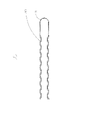
Fig. 2 is the structural representation of the preformed armor rods of the preformed strain clamp of the utility model.
Fig. 3 is the vertical view of the U type connecting ring of the preformed strain clamp of the utility model.
Fig. 4 is the generalized section of positive apparent direction of the U type connecting ring of the preformed strain clamp of the utility model.
Embodiment
Below in conjunction with description of drawings and embodiment the utility model is further specified.
See also Fig. 1 to Fig. 4; The utility model provides a kind of preformed strain clamp 10; Be used for suspended insulated guide wire 100; Preformed strain clamp 10 comprises that preformed armor rods 11 and U type connecting ring 13, preformed armor rods 11 are connected in U type connecting ring 13, and preformed armor rods 11 is connected in insulated conductor 100, and U type connecting ring 13 is connected gold utensil (figure does not show) and connects with shaft tower.
Preformed armor rods 11 comprises holding section 111 and twisting part 113, bending preformed armor rods 11 formation holding sections 111, in the present embodiment; Holding section 111 is an arc; It is understandable that the radian of holding section 111 and length can be provided with as required, holding section 111 is used to be connected in U type connecting ring 13.After preformed armor rods 11 bending, two strands of preformed armor rodses 11 shape in the shape of a spiral curve and form twisting part 113, and twisting part 113 is a helix.Preformed armor rods 11 is made up of wire, and wire is bonding each other through glue.The internal diameter of the twisting part 113 of preformed armor rods 11 is slightly less than the external diameter of insulated conductor 100, and preformed armor rods 11 strains are to provide grip to be fixedly connected insulated conductor 100.Twisting part 113 inboards of preformed armor rods 11 are stained with diamond dust to increase the frictional force that preformed armor rods 11 is connected in insulated conductor 100.Preformed strain clamp 10 also is provided with colour code 15, and colour code 15 is socketed on preformed armor rods 11.
U type connecting ring 13 is provided with cannelure 131, and the holding section 111 of preformed armor rods 11 is connected in the cannelure 131 of U type connecting ring 13.Preformed strain clamp 10 also is provided with bolt 17; U type connecting ring 13 also is provided with fixed part 133; Fixed part 133 comprises two fixed heads 1331 that are parallel to each other, and offers fixing hole 1333 on the fixed head 1331, and fixing hole 1333 is coaxial; Bolt 17 is fixedly connected on the fixing hole 1333 of U type connecting ring 13, and bolt 17 is connected gold utensil and connects with shaft tower.U type connecting ring 13 also is provided with the connecting portion 135 of arc, and connecting portion 135 is connected between the fixed part 133.
The preformed strain clamp 10 of the utility model is connected with insulated conductor 100 through preformed armor rods 11, and preformed armor rods 11 is wound on the insulated conductor 100, has increased the lifting surface area of insulated conductor 100, and has been evenly distributed, and no obvious stress is concentrated; Preformed armor rods 11 adopts metal material to process, and utilizes the strain of metal material to guarantee that the grip of 10 pairs of insulated conductors 100 of preformed strain clamp never disappears, the loosening hidden danger that can not exist bolt 17 to connect; The inboard diamond dust of preformed armor rods 11 have increased the frictional force of 100 of preformed armor rods 11 and insulated conductors, have guaranteed the grip of 10 pairs of insulated conductors 100 of preformed strain clamp.
Above content is the further explain that combines concrete preferred implementation that the utility model is done, and can not assert that the practical implementation of the utility model is confined to these explanations.For the those of ordinary skill of technical field under the utility model, under the prerequisite that does not break away from the utility model design, can also make some simple deduction or replace, all should be regarded as belonging to the protection range of the utility model.

Claims (9)

1. preformed strain clamp; Be used for suspended insulated guide wire; It is characterized in that: said preformed strain clamp comprises that preformed armor rods and U type connecting ring, said preformed armor rods comprise holding section and twisting part; Said twisting part is a helix, and said U type connecting ring offers cannelure, and the holding section of said preformed armor rods is connected in the cannelure of said U type connecting ring.
2. according to the said preformed strain clamp of claim 1, it is characterized in that: said preformed armor rods is made up of many one metal wires.
3. according to the said preformed strain clamp of claim 2, it is characterized in that: said wire is bonding each other through glue.
4. according to the said preformed strain clamp of claim 1, it is characterized in that: the holding section of said preformed armor rods is an arc.
5. according to the said preformed strain clamp of claim 1, it is characterized in that: the twisting part inboard of said preformed armor rods is stained with diamond dust.
6. according to the said preformed strain clamp of claim 1; It is characterized in that: said preformed strain clamp is provided with bolt; Said U type connecting ring is provided with fixed part, and said fixed part comprises two fixed heads that are parallel to each other, and offers fixing hole on the said fixed head; Said fixing hole is coaxial, and said bolt is connected in the fixing hole of said U type connecting ring.
7. according to the said preformed strain clamp of claim 6, it is characterized in that: said U type connecting ring also is provided with connecting portion, and said connecting portion is connected between the said fixed part.
8. according to the said preformed strain clamp of claim 7, it is characterized in that: the connecting portion of said U type connecting ring is an arc.
9. according to the said preformed strain clamp of claim 1, it is characterized in that: said preformed strain clamp also is provided with colour code.
CN2011202688573U 2011-07-27 2011-07-27 Pre-twisted strain clamp Expired - Fee Related CN202167813U (en)

Priority Applications (1)

Application Number Priority Date Filing Date Title
CN2011202688573U CN202167813U (en) 2011-07-27 2011-07-27 Pre-twisted strain clamp

Applications Claiming Priority (1)

Application Number Priority Date Filing Date Title
CN2011202688573U CN202167813U (en) 2011-07-27 2011-07-27 Pre-twisted strain clamp

Publications (1)

Publication Number Publication Date
CN202167813U true CN202167813U (en) 2012-03-14

Family

ID=45803617

Family Applications (1)

Application Number Title Priority Date Filing Date
CN2011202688573U Expired - Fee Related CN202167813U (en) 2011-07-27 2011-07-27 Pre-twisted strain clamp

Country Status (1)

Country Link
CN (1) CN202167813U (en)

Cited By (4)

* Cited by examiner, † Cited by third party
Publication number Priority date Publication date Assignee Title
CN102856863A (en) * 2012-10-08 2013-01-02 江苏天南电力器材有限公司 Preformed strain clamp
CN103730872A (en) * 2013-12-31 2014-04-16 宁波诺驰光电科技发展有限公司 Pre-twisted type strain clamp with monitoring function
CN104071035A (en) * 2013-03-29 2014-10-01 辽宁海澳科技有限公司 Dual protection device for anchoring carrying cable or contact line terminals in electrified railway
CN105313722A (en) * 2014-07-29 2016-02-10 北京盈电电气有限公司 Preformed terminal anchoring protection wire clip

Cited By (6)

* Cited by examiner, † Cited by third party
Publication number Priority date Publication date Assignee Title
CN102856863A (en) * 2012-10-08 2013-01-02 江苏天南电力器材有限公司 Preformed strain clamp
CN102856863B (en) * 2012-10-08 2015-10-07 江苏天南电力器材有限公司 A kind of pre-hinged strain clamp
CN104071035A (en) * 2013-03-29 2014-10-01 辽宁海澳科技有限公司 Dual protection device for anchoring carrying cable or contact line terminals in electrified railway
CN103730872A (en) * 2013-12-31 2014-04-16 宁波诺驰光电科技发展有限公司 Pre-twisted type strain clamp with monitoring function
CN103730872B (en) * 2013-12-31 2016-04-06 浙江中欣动力测控技术有限公司 A kind of pre-hinged strain clamp with monitoring function
CN105313722A (en) * 2014-07-29 2016-02-10 北京盈电电气有限公司 Preformed terminal anchoring protection wire clip

Similar Documents

Publication Publication Date Title
CN105870863A (en) Strain clamp for carbon fiber composite cores
CN202930880U (en) Carbon fiber composite core wire dedicated connection hardware
CN201319488Y (en) Antiskid conductor spacer
CN201011701Y (en) Pre-twisted double strain clamp used for steel core aluminum strand wire
CN105449613B (en) A kind of high-damping type transmission line of electricity aeolian vibration damper
CN105680391B (en) A kind of composite core strengthens cable strain clamp
CN206099253U (en) Protection device that falls is prevented to broken string
CN203674668U (en) Pre-twisted clamp anti-vibration hammer
CN203175139U (en) Novel U-shaped stay wire hoop
CN210957719U (en) Top wire binding type all-insulation color preformed armor rod
CN202308982U (en) Tension wire clamp used for optical phase conductor
CN208890320U (en) A kind of suspension clamp for electric line
CN102141668B (en) Insulated down lead clamp
CN207039143U (en) A kind of tension force keeps wire clamp
CN204418783U (en) A kind of end flange for cross arm
CN202353155U (en) Shockproof hammer used for large-section high voltage conductor
CN204992480U (en) Twist formula wedge strain clamp in advance
CN202503247U (en) Auxiliary terminal hardware fitting for carbon-fiber photoelectric composite lead wire
CN210957730U (en) Double-top wire-binding type all-insulation color-phase preformed armor rod
CN202260358U (en) Waterproof draw gear of high-voltage crosslinked cable
CN202378722U (en) Pre-twisted terminal anchoring cable clamp used for carrier cable
CN201004543Y (en) Pre-twisted damper
CN206293856U (en) A kind of copper-alloy stranded conductor bracing cable is pressed from both sides
CN111048267A (en) Wind vibration resistant fixed suspension insulator string and working method thereof
CN216561131U (en) Anti-flashover pre-twisted wire type strain clamp

Legal Events

Date Code Title Description
C14 Grant of patent or utility model
GR01 Patent grant
PE01 Entry into force of the registration of the contract for pledge of patent right

Denomination of utility model: Preformed strain clamp

Effective date of registration: 20121017

Granted publication date: 20120314

Pledgee: Shenzhen SME credit financing guarantee Group Co., Ltd.

Pledgor: Shenzhen Skyee Optical Fiber Communication Technology Co., Ltd.

Registration number: 2012990000609

PLDC Enforcement, change and cancellation of contracts on pledge of patent right or utility model
PC01 Cancellation of the registration of the contract for pledge of patent right

Date of cancellation: 20131212

Granted publication date: 20120314

Pledgee: Shenzhen SME credit financing guarantee Group Co., Ltd.

Pledgor: Shenzhen Skyee Optical Fiber Communication Technology Co., Ltd.

Registration number: 2012990000609

PE01 Entry into force of the registration of the contract for pledge of patent right

Denomination of utility model: Preformed strain clamp

Effective date of registration: 20131212

Granted publication date: 20120314

Pledgee: Shenzhen high tech investment and financing Company limited by guarantee

Pledgor: Shenzhen Skyee Optical Fiber Communication Technology Co., Ltd.

Registration number: 2013990000963

PLDC Enforcement, change and cancellation of contracts on pledge of patent right or utility model
C56 Change in the name or address of the patentee

Owner name: SHENZHEN SKYEE OPTICAL FIBER COMMUNICATION TECHNOL

Free format text: FORMER NAME: SHENZHEN TIANYI FIBRE-OPTICAL COMMUNICATION TECHNOLOGY CO., LTD.

CP03 Change of name, title or address

Address after: Nanshan District Xueyuan Road in Shenzhen city of Guangdong province 518000 No. 1001 Nanshan Chi Park C3 building 16 floor

Patentee after: Sky, Shenzhen intelligence development net Science and Technology Ltd.

Address before: 518000 Guangdong city of Shenzhen province Nanshan District Xili Street Ma Hom Village Road No. 31 Yimin Industrial Zone Fifth 1-6

Patentee before: Shenzhen Skyee Optical Fiber Communication Technology Co., Ltd.

PC01 Cancellation of the registration of the contract for pledge of patent right

Date of cancellation: 20150128

Granted publication date: 20120314

Pledgee: Shenzhen high tech investment and financing Company limited by guarantee

Pledgor: Sky, Shenzhen intelligence development net Science and Technology Ltd.

Registration number: 2013990000963

PLDC Enforcement, change and cancellation of contracts on pledge of patent right or utility model
PM01 Change of the registration of the contract for pledge of patent right

Change date: 20150128

Registration number: 2013990000963

Pledgor after: Sky, Shenzhen intelligence development net Science and Technology Ltd.

Pledgor before: Shenzhen Skyee Optical Fiber Communication Technology Co., Ltd.

CF01 Termination of patent right due to non-payment of annual fee

Granted publication date: 20120314

Termination date: 20180727