CN202153478U - Capacitor with fixing clamp - Google Patents
Capacitor with fixing clamp Download PDFInfo
- Publication number
- CN202153478U CN202153478U CN2011202910516U CN201120291051U CN202153478U CN 202153478 U CN202153478 U CN 202153478U CN 2011202910516 U CN2011202910516 U CN 2011202910516U CN 201120291051 U CN201120291051 U CN 201120291051U CN 202153478 U CN202153478 U CN 202153478U
- Authority
- CN
- China
- Prior art keywords
- capacitor
- geometrical clamp
- clip
- fixed part
- electric capacity
- Prior art date
- Legal status (The legal status is an assumption and is not a legal conclusion. Google has not performed a legal analysis and makes no representation as to the accuracy of the status listed.)
- Expired - Fee Related
Links
Images
Landscapes
- Shielding Devices Or Components To Electric Or Magnetic Fields (AREA)
Abstract
Provided is a capacitor with a fixing clamp, comprising a housing, a capacitor cover, and a capacitor core arranged inside the housing, wherein the capacitor cover is provided with a fixing clamp; the fixing clamp comprises a fixing part, a reinforcing rib, and a clip; the fixing part is fixedly installed upon the top surface of the capacitor cover; one end of the clip is connected to one end of the fixing part via the reinforcing rib and is also fixed to the side surface of the capacitor cover; and the other end of the clip, under an external force, is opened within certain angles. The capacitor with a fixing clamp can be clamped to the to-be-installed members via the clamp arranged upon the housing, thereby being easy in operation.
Description
Technical field
The utility model relates to the technical field of capacitor, particularly a kind of capacitor that has geometrical clamp.
Background technology
On industrial circuit application, in order effectively to transmit or to change electric energy, improve its power factor, use capacitor usually.Capacitor is to be made up of two very near metal electrodes of being separated by again insulated from each other, is widely used in the integrated circuits such as analog circuit, hybrid circuit.In semiconductor integrated circuit, common capacitor has metal-insulator-metal type (MIM, Metal-Insulator-Metal) capacitor, metal-oxide-metal (MOM, Metal-Oxide-Metal) capacitor.But existing capacitor when mounted, generally need fix capacitor with adhesive tape or metal skin.
In view of this, the utility model embodiment has proposed the capacitor that a kind of installation has geometrical clamp simply and easily.
Summary of the invention
For solving the problems of the technologies described above, the purpose of the utility model embodiment realizes through following technical scheme:
The capacitor that has geometrical clamp that the utility model provides; Comprise that shell, electric capacity cover and be positioned at the capacitance core of shell, said electric capacity covers geometrical clamp is installed, and said geometrical clamp comprises fixed part, reinforcement, clip; Said fixed part is fixedly mounted on the end face of electric capacity lid; One end of said clip is connected an end of fixed part through reinforcement, and is fixed on the side of electric capacity lid, and the said clip other end opens in certain angle under the effect of external force.
Preferably, said geometrical clamp also comprises lug, and said lug is fixed on the other end of fixed part, and vertical with said fixed part.
Preferably, said lug is provided with screw.
The capacitor that has geometrical clamp that the utility model provides needs on the mounted component through being installed in the clip on the shell, can being clamped in, and is easy to operate.
Description of drawings
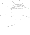
Fig. 1 has the structural representation of the capacitor of geometrical clamp for the utility model.
Embodiment
The utility model provides a kind of capacitor that has geometrical clamp.Said capacitor comprises shell, electric capacity lid and is positioned at the capacitance core of shell; Said electric capacity covers geometrical clamp is installed; Said geometrical clamp comprises fixed part, reinforcement, clip, and said fixed part is fixedly mounted on the end face of electric capacity lid, and an end of said clip is connected an end of fixed part through reinforcement; And be fixed on the side of electric capacity lid, the said clip other end opens in certain angle under the effect of external force.
Further describe below in conjunction with specific embodiment.
See also Fig. 1, have the structural representation of the capacitor of geometrical clamp for the utility model.
The capacitor that has geometrical clamp mainly comprises shell 10, electric capacity lid 20, is positioned at the capacitance core (figure does not show) of shell 10.
On the said electric capacity lid 20 geometrical clamp 30 is installed.Said geometrical clamp 30 comprises fixed part 31, reinforcement 32, clip 33, lug 34.
Said fixed part 31 is fixedly mounted on the end face of electric capacity lid 20.
One end of said clip 33 is connected an end of fixed part 31 through reinforcement 32, and is fixed on the side of electric capacity lid 20.Said clip 33 other ends can open in certain angle under the effect of external force.
Said lug 34 is fixed on the other end of said fixed part 31, and vertical with said fixed part 31.Said lug 34 is provided with screw.
Capacitor can be clamped in through said geometrical clamp 30 to be needed on the mounted component.Also can be fixed on through the screw on the lug 34 needs on the mounted component.
In sum, the capacitor that has geometrical clamp that the utility model embodiment is provided needs on the mounted component through being installed in the clip on the shell, can being clamped in, and is easy to operate.
More than the capacitor that has geometrical clamp that the utility model embodiment is provided carried out detailed introduction; Used concrete example among this paper the principle and the execution mode of the utility model are set forth, the explanation of above embodiment just is used to help to understand the technical scheme that the utility model discloses; Simultaneously, for one of ordinary skill in the art, according to the thought of the utility model, the part that on embodiment and range of application, all can change, in sum, this description should not be construed as the restriction to the utility model.
Claims (3)
1. a capacitor that has geometrical clamp is characterized in that, comprises that shell, electric capacity cover and be positioned at the capacitance core of shell; Said electric capacity covers geometrical clamp is installed; Said geometrical clamp comprises fixed part, reinforcement, clip, and said fixed part is fixedly mounted on the end face of electric capacity lid, and an end of said clip is connected an end of fixed part through reinforcement; And be fixed on the side of electric capacity lid, the said clip other end opens in certain angle under the effect of external force.
2. the capacitor that has geometrical clamp according to claim 1 is characterized in that said geometrical clamp also comprises lug, and said lug is fixed on the other end of fixed part, and vertical with said fixed part.
3. the capacitor that has geometrical clamp according to claim 2 is characterized in that said lug is provided with screw.
Priority Applications (1)
| Application Number | Priority Date | Filing Date | Title |
|---|---|---|---|
| CN2011202910516U CN202153478U (en) | 2011-08-11 | 2011-08-11 | Capacitor with fixing clamp |
Applications Claiming Priority (1)
| Application Number | Priority Date | Filing Date | Title |
|---|---|---|---|
| CN2011202910516U CN202153478U (en) | 2011-08-11 | 2011-08-11 | Capacitor with fixing clamp |
Publications (1)
| Publication Number | Publication Date |
|---|---|
| CN202153478U true CN202153478U (en) | 2012-02-29 |
Family
ID=45693972
Family Applications (1)
| Application Number | Title | Priority Date | Filing Date |
|---|---|---|---|
| CN2011202910516U Expired - Fee Related CN202153478U (en) | 2011-08-11 | 2011-08-11 | Capacitor with fixing clamp |
Country Status (1)
| Country | Link |
|---|---|
| CN (1) | CN202153478U (en) |
-
2011
- 2011-08-11 CN CN2011202910516U patent/CN202153478U/en not_active Expired - Fee Related
Similar Documents
| Publication | Publication Date | Title |
|---|---|---|
| CN203277089U (en) | Capacitor and a mainboard using same | |
| CN203931784U (en) | Novel conjoined formula current transformer | |
| CN203761346U (en) | Simple crystal resonator | |
| CN202167354U (en) | Buckle type housing for capacitor | |
| CN203013510U (en) | Capacitor with arched bench inside | |
| CN203166378U (en) | Novel 24kV voltage transformer handcart | |
| CN202058592U (en) | Multi-capacitance combined type capacitor | |
| CN201498354U (en) | Reinforced insulation current transformer | |
| CN204720325U (en) | Monolithic devices button super capacitor | |
| CN202931206U (en) | Direct current busbar specially used for active power filter | |
| CN203180374U (en) | Portable waterproof distribution box | |
| CN202363258U (en) | Flat-head extraction electrode for capacitor | |
| CN202153480U (en) | One-body simplified capacitor | |
| CN203562304U (en) | Capacitor cover plate explosion-proof block | |
| CN203896176U (en) | Small four-quadrant explosion-proof frequency conversion machine core | |
| CN203039536U (en) | End cover of asynchronous motor | |
| CN202737007U (en) | Battery cell | |
| CN202167349U (en) | One-piece waterproof capacitor | |
| CN201742099U (en) | Capacitor for three-phase separate-supplement intelligent capacitor | |
| CN202159577U (en) | Capacitor with protection device | |
| CN201732687U (en) | Cross error proofing terminal cover plate | |
| CN202514225U (en) | Framework of electric cabinet | |
| CN203820217U (en) | Mounting structure of controlling box of elevator | |
| CN204720312U (en) | Anti-lost type buckle capacitive storage devices | |
| CN204067059U (en) | A kind of capacitor cover plate being convenient to scolding tin |
Legal Events
| Date | Code | Title | Description |
|---|---|---|---|
| C14 | Grant of patent or utility model | ||
| GR01 | Patent grant | ||
| CF01 | Termination of patent right due to non-payment of annual fee |
Granted publication date: 20120229 Termination date: 20150811 |
|
| EXPY | Termination of patent right or utility model |