CN202107989U - Eccentric steel structure bridge pier coping positioned below main girder of circular arc ramp ridge - Google Patents
Eccentric steel structure bridge pier coping positioned below main girder of circular arc ramp ridge Download PDFInfo
- Publication number
- CN202107989U CN202107989U CN2011201582853U CN201120158285U CN202107989U CN 202107989 U CN202107989 U CN 202107989U CN 2011201582853 U CN2011201582853 U CN 2011201582853U CN 201120158285 U CN201120158285 U CN 201120158285U CN 202107989 U CN202107989 U CN 202107989U
- Authority
- CN
- China
- Prior art keywords
- bridge
- pier
- former
- bridge pier
- pier stud
- Prior art date
- Legal status (The legal status is an assumption and is not a legal conclusion. Google has not performed a legal analysis and makes no representation as to the accuracy of the status listed.)
- Expired - Fee Related
Links
- 229910000831 Steel Inorganic materials 0.000 title claims abstract description 153
- 239000010959 steel Substances 0.000 title claims abstract description 153
- 230000010485 coping Effects 0.000 title abstract 5
- 230000002787 reinforcement Effects 0.000 claims abstract description 41
- 239000004567 concrete Substances 0.000 claims abstract description 21
- 238000003466 welding Methods 0.000 claims abstract description 9
- 239000007787 solid Substances 0.000 claims description 29
- 230000003014 reinforcing effect Effects 0.000 claims description 12
- 238000009434 installation Methods 0.000 claims description 5
- 238000005520 cutting process Methods 0.000 claims description 3
- 239000011150 reinforced concrete Substances 0.000 claims description 3
- 238000000034 method Methods 0.000 abstract description 4
- 239000000835 fiber Substances 0.000 abstract description 2
- 230000006835 compression Effects 0.000 abstract 1
- 238000007906 compression Methods 0.000 abstract 1
- 230000000149 penetrating effect Effects 0.000 abstract 1
- 238000010276 construction Methods 0.000 description 3
- 230000015572 biosynthetic process Effects 0.000 description 2
- 230000005484 gravity Effects 0.000 description 2
- 229920001084 poly(chloroprene) Polymers 0.000 description 2
- 239000011398 Portland cement Substances 0.000 description 1
- 238000005452 bending Methods 0.000 description 1
- 238000009826 distribution Methods 0.000 description 1
- 238000005516 engineering process Methods 0.000 description 1
- 230000007774 longterm Effects 0.000 description 1
- 238000003754 machining Methods 0.000 description 1
- 238000004519 manufacturing process Methods 0.000 description 1
- 238000002360 preparation method Methods 0.000 description 1
- 239000004576 sand Substances 0.000 description 1
- 239000004575 stone Substances 0.000 description 1
- XLYOFNOQVPJJNP-UHFFFAOYSA-N water Substances O XLYOFNOQVPJJNP-UHFFFAOYSA-N 0.000 description 1
Images




Landscapes
- Bridges Or Land Bridges (AREA)
Abstract
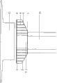
The utility model relates to an eccentric steel structure bridge pier coping positioned below a main girder of a circular arc ramp bridge. The eccentric steel structure bridge pier coping is positioned at the top part of an eccentric reinforcement body of a pier column, and the bearing reaction provided by the eccentric steel structure bridge pier coping is matched with the eccentric compression exerted by the main girder of the ramp bridge. The eccentric steel structure bridge pier coping is composed of a bottom plate, two wing plates, eight double-cantilever plates, seven rows of channel steel connecting bodies, twenty-three penetrating main tensile reinforcements, seven rows of lock catches, two decorative boards, a pier column top of the original bridge with height of 1170 mm and C30 non-shrinkage steel fiber concrete for pouring. All steel components of the utility model can be mechanically manufactured in workshops, so as to have high precision and good quality. The steel components are assembled together with bolts by welding, so as to have beautiful appearance, firm texture and excellent physical and mechanical performance. During the whole field assembly process, the traffic on the bridge floor is unnecessarily interrupted, and the assembly process can be tightly matched with the operating process of the main girder of the roof propping ramp bridge.
Description
Technical field
The utility model relates to a kind of eccentric steel work bridge pier bent cap that is positioned under the circular curve ramp bridge girder.
Background technology
In metropolitan city, between the main road of interchange viaduct, big multi-link circular curve ramp bridge.This ramp bridge is one with the 2-4 hole, and the top supporting member of each couplet is the Prestressed Continuous box-girder of one single box single chamber, the wide 3.5-4.5m of its underpart case, and the wide 8.0-9.0m of its end face carriageway plate, its deck profile grade is 1-3%.At the two ends of each couplet, adopt abutment or two-columned pier to support; At the middle part of each couplet, adopt the single-columned pier on drilled pile basis to support.At the top of abutment or two-columned pier, be equipped with a bent cap.At the end face of this bent cap, pasting two boards formula neoprene bearing side by side and supporting the ramp bridge girder.The single-columned pier pier stud is the Reinforced Concrete Circular Cylinder body that a diameter is 1400-1600mm, and it is located in the position, center of pier cap, and its end face is installed a pot bearing, to support the ramp bridge girder.
So-called circular curve ramp bridge, the longitudinal central axis line of its girder is one circular curve.Through this circular curve do one with the perpendicular circular arc camber of horizontal plane, this circular arc camber is the circular arc camber of this ramp bridge, its radius is 150-300m.The vertical axis of each single-columned pier pier stud of this ramp bridge all is positioned on this circular arc camber, and the center of gravity line of ramp bridge girder and the center of gravity line of wagon flow then are positioned at the circular arc camber 100-200mm place in addition of this ramp bridge.At the two ends of circular curve ramp bridge, at the end face of pier bent cap, the two boards formula neoprene bearing outside circular arc camber draws a straight line, and this straight line is the rotating shaft A of whole ramp bridge girder.In the outside of rotating shaft A, be the main body of ramp bridge girder, its weight accounts for the 70-90% of gross weight; In the inboard of rotating shaft A, be the part at ramp bridge girder two ends, its weight only accounts for the 30-10% of gross weight.
Under the long-term effect of eccentric vertical pressure and centrifugal force, in the outside of rotating shaft A, the main body of ramp bridge girder is sunk; In the inboard of rotating shaft A, the two ends of the ramp bridge girder warpage that makes progress.Meanwhile, whole ramp bridge girder produces translation to the outside of rotating shaft A.When the construction quality of ramp bridge was relatively poor, this kind phenomenon was with even more serious.Repair the circular curve ramp bridge, at first its girder is carried out translation, and then upwards prop up the top, make its girder return to the position of this bridge when just being completed.Under the girder of ramp bridge, make a pier stud off-centre in the outside of single-columned pier pier stud and add solid, make this pier stud become eight prisms of direction across bridge, to increase its bending resistance by cylinder.The vertical axis of whole pier stud to the outside of the circular arc camber of this ramp bridge translation 100-200mm, is formed an eccentric bridge pier pier stud.End face at this off-centre bridge pier pier stud adds an eccentric bridge pier bent cap, and the eccentricity pressure that support reaction that this eccentric bridge pier bent cap is provided and ramp bridge girder are applied matches.
The utility model is exactly to this above-mentioned conception and by the eccentric bridge pier bent cap of a kind of novel open side type of the meticulous development of the inventor.In the process of whole making, need not interruption of bridge deck traffic, need not to destroy greenery patches under the bridge, formed eccentric steel work bridge pier bent cap is handsome in appearance, and quality is firm, and can add integral body of solid and former bridge pier pier stud top formation with the pier stud off-centre of its below.
The utility model content
The utility model problem to be solved just provides the eccentric bridge pier bent cap of a kind of novel open side type, and in order to supporting the girder of circular curve ramp bridge, the eccentricity pressure that is applied with the ramp bridge girder of the support reaction that this off-centre bridge pier bent cap is provided matches.The utility model is to form through field fabrication at the end face that pier stud off-centre adds solid, and it wraps into former bridge pier pier stud top among himself, and becomes its important component part.
The purpose of the utility model realizes through following technical scheme:
A kind of eccentric steel work bridge pier bent cap that is positioned under the circular curve ramp bridge girder; The longitudinal central axis line of described its girder of circular curve ramp bridge is one circular curve; Through this circular curve do one with the perpendicular circular arc camber of horizontal plane; This circular arc camber is the circular arc camber of this circular curve ramp bridge, and the vertical axis of each the former bridge pier pier stud under the described ramp bridge girder all is positioned on this circular arc camber; Eccentric steel work bridge pier bent cap according to the utility model made is characterized in that:
Described eccentric steel work bridge pier bent cap include 1 base plate, 2 blocks of wing plates, 2 blocks of side plates, the two outrigger bases in 8 roads, 7 emissions groove steel connectors, 23 connect high former bridge pier pier stud top of tension main reinforcement, 7 row's snap closes, 2 packaged plaques, 1170mm and the C30 non-shrinking steel fibrous concrete of being poured into a mould; The high 1230mm of this off-centre steel work bridge pier bent cap, it is located in the end face that pier stud off-centre adds solid, and its end face is apart from the bottom surface 180mm of described ramp bridge girder, is described former bridge pier pier stud top between wherein; See that from geometric figure described eccentric steel work bridge pier bent cap can be divided into two parts up and down, top is a rectangular cylinder, and the lower part is a flat trapezoidal cylinder that crouches; This rectangular column height 630mm; The width that its length along direction across bridge equals described ramp bridge girder adds 600mm; Its along vertical bridge to the width diameter that equals described former bridge pier pier stud add 320mm, the vertical bridge of its end face is tangent to the circular arc camber of axis and described circular curve ramp bridge; This trapezoidal column height 600mm, its front and back sides are two identical trapezoidal vertical planes, and its left and right side is the rectangle plane of two inclinations, and its end face and bottom surface are all the rectangle plane of level; This end face and bottom surface along vertical bridge to the width diameter that all equals described former bridge pier pier stud add 160mm; This end face adds 600mm along the width that the length of direction across bridge equals described ramp bridge girder, and its vertical bridge is tangent to the circular arc camber of axis and described circular curve ramp bridge; This bottom surface is along the long 2400mm of direction across bridge, and its vertical bridge is positioned at the circular arc camber 100-200mm place in addition of described circular curve ramp bridge to the axis; At the intersection of former bridge pier pier stud top and former bridge pier pier stud main body, make the gap of one circular concrete cover round former bridge pier pier stud, it is long to make every vertical reinforcement of its reinforcing cage all expose 50mm; Described base plate is level and makes; In the left and right sides of this base plate, outwards be followed successively by described wing plate and side plate from the lining; The edge in the front and back of this base plate, front and back are respectively installed 1 described decorative panel symmetrically; These steel plates have constituted the steel sheel of described eccentric steel work bridge pier bent cap jointly; In this steel sheel, between 2 described decorative panels, to have made the described pair of outrigger base in 8 roads before and after the spacing that equates symmetrically altogether; Between the two outrigger bases in every 2 adjacent roads, all make 1 described channel-section steel connector of row and the described snap close of 1 row; Described perforation tension main reinforcement build-in is in the horizontal cut of this snap close and the end face that is tiled in described its upper cross plate of decorative panel; Described decorative panel is made up of last riser, following riser, upper cross plate and lower cross plate; In above-mentioned formed steel work, all spaces all have been full of the C30 non-shrinking steel fibrous concrete of being poured into a mould.
Described former bridge pier pier stud is the Reinforced Concrete Circular Cylinder body that a diameter is 1400-1600mm, and it has constituted a former single-columned pier that does not have the bridge pier bent cap with pier cap; Former bridge pier pier stud be positioned at described ramp bridge girder under, its height in 10m, its root is located in the position, center of pier cap, its vertical axis is positioned on the circular arc camber of described circular curve ramp bridge; Whole former bridge pier pier stud is divided into former bridge pier pier stud top and former bridge pier pier stud main body two parts from top to bottom; Within described eccentric steel work bridge pier bent cap, the former bridge pier pier stud high 1170mm in top.
At the intersection of described former bridge pier pier stud top and former bridge pier pier stud main body, make the gap of one circular concrete cover round former bridge pier pier stud, it is long to make every vertical reinforcement of its reinforcing cage all expose 50mm; Described base plate is made with a thick rectangular steel plates of 20mm, in this base plate, is provided with the circular hole that a diameter equals described former bridge pier pier stud reinforcing cage external diameter; The center of circle through this circular hole be provided with together vertical bridge to piece, about this base plate is divided into two; These two base plates embed in the gap of circular concrete cover of former bridge pier pier stud from the left and right sides respectively, implement the straight joint full weld at its seam place of abandoning, and make this base plate form an integral body; In the intersection of each root vertical reinforcement of this base plate and former bridge pier pier stud reinforcing cage, the length of its weld bond all is not less than 20mm.
Described pier stud off-centre adds solid and is wrapped in described former bridge pier pier stud main body, and its width along direction across bridge is 2200mm, along vertical bridge to thickness equal the diameter of described former bridge pier pier stud, its four chamferings are 400 * 100mm; Described base plate is positioned at the end face that pier stud off-centre adds solid, and this is a steel member of forming a connecting link, and it is the base plate of eccentric steel work bridge pier bent cap, is again the top board of eccentric steel work bridge pier pier stud; This top board adds solid and former bridge pier pier stud main body with pier stud off-centre, has constituted an eccentric steel work bridge pier pier stud; The vertical axis of this eccentric steel work bridge pier pier stud is positioned at the circular arc camber 100-200mm place in addition of described circular curve ramp bridge.
Add the end face of solid in described pier stud off-centre, described base plate is level and makes, and its length along the long limit of direction across bridge is 2400mm, along indulge bridge to the length of the minor face diameter that equals described former bridge pier pier stud add 160mm; Its end face is lower than the end face 1150mm of former bridge pier pier stud; Its vertical bridge is positioned at the circular arc camber 100-200mm place in addition of described circular curve ramp bridge to the axis; Its two minor faces lay respectively at the 100mm place that pier stud off-centre adds the outside about solid, and its two long limits lay respectively at the 80mm place that pier stud off-centre adds the outside, solid front and back; Adding the intersection of solid steel casing top margin in this base plate bottom surface and pier stud off-centre, is the weld bond of border straight joint full weld.
About described wing plate is divided into two, they all are the thick rectangular steel plates of 6mm, and are installed in the left and right sides of described base plate respectively; The interior longitudinal edge of this wing plate and outer longitudinal edge along indulge bridge to, length equals the length of base plate minor face, the horizontal projection of its former and later two horizontal edges is along direction across bridge; The interior longitudinal edge of these two blocks of wing plates splices with the left and right sides minor face of base plate respectively mutually, and implements the straight joint full weld at its edge joint position; The outer longitudinal edge of these two blocks of wing plates all is higher than longitudinal edge 600mm in it, and stretches out 300mm to the left and right sides of described ramp bridge girder respectively; The left and right sides at described former bridge pier pier stud top, these two blocks of wing plates are asymmetric state.
Described side plate is the thick rectangular steel plates of 6mm, about on the outer longitudinal edge of two blocks of described wing plates, each along vertical bridge to 1 block of side plate of vertical making and settlement; The vertical edge of this side plate vertically, high 630mm, its top longitudinal edge and end longitudinal edge along vertical bridge to, the diameter that length equals described former bridge pier pier stud adds 320mm; The end longitudinal edge of this side plate splices with the outer longitudinal edge of the same side wing plate mutually, and implements the straight joint full weld at its edge joint position; Their top longitudinal edge all is lower than the bottom surface 180mm of described ramp bridge girder, and its former and later two vertical edges are respectively to the front side and the rear side of the wing plate of welding stretch out 80mm mutually with it; The left and right sides at described former bridge pier pier stud top, these two blocks of side plates are symmetrical.
The described pair of outrigger base made with the thick steel plate of 6mm, it by about two asymmetrical parts constitute; These two parts vertically make respectively in the left and right sides at described former bridge pier pier stud top along direction across bridge; The inner side edge of its each part all pastes with the steel casing at former bridge pier pier stud top mutually; Outer side edges respectively with about two blocks of described side plates paste mutually; All paste with described base plate mutually on the base, hypotenuse respectively with about two blocks of described wing plates paste mutually, all implement the straight joint full weld in subsides place mutually of per two block plates; The top margin of this pair outrigger base is higher than described former bridge pier pier stud end face 30mm, and is lower than the top longitudinal edge 30mm of described side plate.
Described channel-section steel connector is tailored with channel-section steel and is formed, and its width equals the clear distance of described pair of outrigger base of adjacent twice; Described snap close is made with the angle steel of 30 * a 30 * 4mm, and its length equals the width of described channel-section steel connector; An end face that the plane is this snap close of this root angle steel, another plane is its vertical plane; In the two ends and the centre of this root angle steel, go up separately and the horizontal cut of wide 24mm of following cutting, dark 12mm; Described channel-section steel connector makes a snap close in vertical state on its top margin; Splice with the top margin of this channel-section steel connector mutually on the base of this snap close vertical plane, implements the straight joint full weld at its edge joint position.
Between described pair of outrigger base of adjacent twice, the channel-section steel connector that has snap close is that perpendicular spacing makes with 300mm along direction across bridge; The top margin of this channel-section steel connector and the end face of snap close are lower than the top margin 48mm and the 18mm of described pair of outrigger base respectively; In the installation position of this channel-section steel connector, one pair of outrigger base clamped in the side of former and later two channel-section steel connectors, through the 1 row bolt that is made from top to bottom they is fixed together tightly; The diameter of these bolts is 12mm, and spacing is 150mm; In the side of channel-section steel connector and subsides place mutually of described pair of outrigger base, the straight joint full weld is all implemented in subsides place mutually on its base with described base plate or wing plate; About the medial surface of two blocks of side plates, through implementing the straight joint full weld, a snap close also is installed respectively, the end face of this snap close is lower than the top margin 18mm of described pair of outrigger base equally.
Described perforation tension main reinforcement uses diameter to tailor as the indented bars of 22mm and forms, and the width that its length equals described ramp bridge girder adds 588mm; In breach, 1 of each build-in connects the tension main reinforcement at each 3 horizontal row of arranging described snap close; The perforation tension main reinforcement of build-in in the horizontal cut at these snap close two ends, the one of which side is pasted with the two outrigger bases in 1 road mutually, and opposite side pastes with the side of these horizontal cuts mutually; Perforation tension main reinforcement in the horizontal cut of build-in in the middle of this snap close, paste with two sides of these horizontal cuts respectively mutually its both sides; The outside at the two outrigger base tops of 2 road limit portion in front and back respectively has 1 to connect the subsides mutually with it of tension main reinforcement, and this perforation tension main reinforcement is tiled in the end face of described its upper cross plate of decorative panel; Connecting of mutually subsides place of tension main reinforcement, all implement the straight joint full weld with two outrigger bases and horizontal cut side; Its two ends with about the intersection of two blocks of side plates, all implement welding.
Described decorative panel riser on it, riser, upper cross plate and lower cross plate all are to tailor with the thick steel plate of 6mm to form down; Last riser is a rectangle, and the width that its length equals described ramp bridge girder adds 588mm, and it highly is 630mm; Following riser is trapezoidal, and the width that the length of its top margin equals described ramp bridge girder adds 588mm, bottom side length 2400mm, and it highly is 580mm; Upper cross plate is identical rectangle with lower cross plate, and the width that its length equals described ramp bridge girder adds 588mm, and its width is 154mm.
The last riser of described decorative panel vertically makes along direction across bridge; Its two vertical edges respectively with about two blocks of described side plates paste mutually; The vertical edge of its lateral surface and these two blocks of side plates is in the same plane, and the top longitudinal edge of its top margin and these two blocks of side plates is in the same plane; The following riser of this decorative panel vertically makes along direction across bridge, and its base is positioned on the described base plate, its two waist respectively with about two blocks of described wing plates paste mutually, the long limit of its lateral surface and this base plate and the horizontal edge of these two blocks of wing plates all are in the same plane; The upper cross plate of this decorative panel and lower cross plate all make along the direction across bridge level, and all paste with the lateral surface of limit portion described pair of outrigger base mutually on long limit in it, and all paste with the described medial surface of going up riser mutually on its foreign minister limit; The end face of this upper cross plate is lower than the top margin 30mm of two outrigger bases, and the bottom surface of this lower cross plate and the base of last riser are in the same plane, and paste mutually with the top margin of following riser; In subsides place mutually of per two block plates, all implement the straight joint full weld.
The utility model has the advantages that: preparation method is simple, and physical and mechanical property is good, and its all steel member all can carry out machining in the workshop, thereby precision is high, and quality is good.At the construction field (site), can assemble through welding and bolt.The utility model is convenient to add in pier stud off-centre the end face making of solid, and can add solid and solid integral body of former bridge pier pier stud top formation with this pier stud off-centre.
Description of drawings
Fig. 1 is the front schematic view of the utility model Central Plains bridge pier pier stud and ramp bridge girder.
Fig. 2 is the side schematic view of the utility model Central Plains bridge pier pier stud and ramp bridge girder.
Fig. 3 is the front schematic view of dividing former bridge pier pier stud top and former bridge pier pier stud main body in the utility model.
Fig. 4 is a side schematic view of dividing former bridge pier pier stud top and former bridge pier pier stud main body in the utility model.
Fig. 5 adds the front schematic view that pier stud off-centre adds solid in the utility model.
Fig. 6 adds the side schematic view that pier stud off-centre adds solid in the utility model.
Fig. 7 is the vertical section sketch map of the two outrigger bases of steel member between wherein of the utility model.
Fig. 8 is the vertical section sketch map of the steel member of the utility model along the eccentric reinforcing of pier stud body side surface.
Fig. 9 is the floor map of two outrigger bases of the utility model.
Figure 10 is the floor map of the base plate of the utility model.
Figure 11 is the floor map of the wing plate of the utility model.
Figure 12 is the floor map of the side plate of the utility model.
Figure 13 is the vertical schematic cross-sectional view of the decorative panel of the utility model.
Figure 14 is the front schematic view of the decorative panel of the utility model.
Figure 15 is the channel-section steel connector and the combined schematic rear view of snap close of the utility model.
Figure 16 is the channel-section steel connector and the combined front schematic view of snap close of the utility model.
Figure 17 is the channel-section steel connector and the combined side schematic view of snap close of the utility model.
Figure 18 is the end face sketch map of the snap close of the utility model.
Figure 19 is the two outrigger bases of the utility model and the plane distribution sketch map of decorative panel.
Figure 20 is the horizontal profile sketch map of the steel work of the utility model along channel-section steel connector end face.
Figure 21 is that the steel work of the utility model is not installed the floor map that connects the tension main reinforcement.
Figure 22 is the floor map after the Steel Structure Installation of the utility model connects the tension main reinforcement.
Figure 23 is the floor map of the utility model.
Figure 24 is the front schematic view of the utility model.
Figure 25 is the side schematic view of the utility model.
Reference numeral
1 base plate, 2 wing plates, 3 side plates, 4 pairs of outrigger bases, 5 channel-section steel connectors, 6 connect tension main reinforcement, 7 snap closes; 8 decorative panels, 9 former bridge pier pier studs, 10 pier stud off-centre add solid, 11 C30 non-shrinking steel fibrous concretes, 12 ramp bridge girders, 13 eccentric steel work bridge pier bent caps, 14 former pot bearings; 15 new board-like bearings, the long limit of 1-1,1-2 minor face, 1-3 circular hole, 1-4 piece, longitudinal edge in the 2-1 horizontal edge, 2-2; The outer longitudinal edge of 2-3,3-1 vertical edge, 3-2 top longitudinal edge, longitudinal edge at the bottom of the 3-3,4-1 inner side edge, 4-2 outer side edges; The 4-3 top margin, 4-4 base, 4-5 hypotenuse, 7-1 end face, 7-2 vertical plane, 7-3 horizontal cut; The last riser of 8-1, riser under the 8-2,8-3 upper cross plate, 8-4 lower cross plate, the former bridge pier pier stud of 9-1 top, the former bridge pier pier stud of 9-2 main body
1-25 is elaborated to the utility model below in conjunction with accompanying drawing.
The specific embodiment
Shown in accompanying drawing 1-25: the utility model connects the high former bridge pier pier stud top 9-1 of the packaged plaque of tension main reinforcement 6,7 row's snap closes 7,28,1170mm by 5,23 of two outrigger base 4, the 7 emissions groove steel connectors in 2,2 side plate 3,8 roads of 1,2 blocks of wing plates of 1 base plate and the C30 non-shrinking steel fibrous concrete of being poured into a mould 11 constitutes.
The base plate 1 of eccentric steel work bridge pier bent cap 13 is steel members of forming a connecting link, and when former bridge pier pier stud 9 was reinforced, it was the top board that pier stud off-centre adds solid 10.The base plate 1 of installation in position is the level of state, and its length along the long limit of direction across bridge is 2400mm, along vertical bridge to the length of the minor face diameter that equals former bridge pier pier stud 9 add 160mm; Its end face is lower than the end face 1150mm of former bridge pier pier stud 9; Its vertical bridge is positioned at the circular arc camber 100-200mm place in addition of circular curve ramp bridge to the axis; Its two minor faces lay respectively at the 100mm place that pier stud off-centre adds solid about 10 outsides, and its two long limits lay respectively at the 80mm place that pier stud off-centre adds the outside, solid 10 front and back; Adding the intersection of solid 10 steel casing top margins in this base plate 1 bottom surface and pier stud off-centre, is the weld bond of border straight joint full weld.
The rectangular steel plates that 20mm of base plate 1 usefulness is thick is made, and in this rectangular steel plates, is provided with the circular hole 1-3 that a diameter equals former bridge pier pier stud 9 reinforcing cage external diameters.Be provided with 1 road piece 1-4 along vertical bridge to the center of circle, about base plate 1 is divided into two through this circular hole 1-3.At the intersection of former bridge pier pier stud top 9-1 and former bridge pier pier stud main body 9-2,, make every vertical reinforcement of its reinforcing cage all expose 50mm length round the gap of one circular concrete cover of former bridge pier pier stud 9 making and settlement.Separated two base plates 1 embed in this gap from the left and right sides respectively, implement the straight joint full weld at its splicing-in seam 1-4 place, make it to form an integral body.In the intersection of base plate 1 with each root vertical reinforcement of former bridge pier pier stud 9 reinforcing cages, the length of its weld bond all is not less than 20mm.
About wing plate 2 is divided into two, they all are the thick rectangular steel plates of 6mm, and are installed in the left and right sides of base plate 1 respectively.The interior longitudinal edge 2-2 of this wing plate 2 and outer longitudinal edge 2-3 along vertical bridge to, length equals the length of base plate 1 minor face 1-2, the horizontal projection of 2 the horizontal edge 2-1 in its front and back is along direction across bridge.The interior longitudinal edge 2-2 of these two blocks of wing plates 2 splices with the left and right sides minor face 1-2 of base plate 1 respectively mutually, and implements the straight joint full weld at its edge joint position.The outer longitudinal edge 2-3 of these two blocks of wing plates 2 is than the high 600mm of longitudinal edge 2-2 in it, and stretches out 300mm to the left and right sides of ramp bridge girder 12 respectively.The left and right sides at former bridge pier pier stud top 9, these two blocks of wing plates 2 are asymmetric state.
The thick steel plate of two outrigger base 4 usefulness 6mm is manufactured, it by about two asymmetrical parts constitute.These two parts vertically make respectively in the left and right sides of former bridge pier pier stud top 9-1 along direction across bridge; The inner side edge 4-1 of its each part pastes with the steel casing of former bridge pier pier stud top 9-1 mutually; Outer side edges 4-2 respectively with about two blocks of side plates 3 paste mutually; Base 4-4 all pastes with base plate 1 mutually, hypotenuse 4-5 respectively with about two blocks of wing plates 2 paste mutually.The straight joint full weld is all implemented in subsides place mutually at per two block plates.The top margin 4-3 of this pair outrigger base 4 is higher than former bridge pier pier stud 9 end face 30mm, and the low 30mm of the top longitudinal edge 3-2 of two blocks of side plates 3 about ratio.With regard to whole eccentric steel work bridge pier bent cap 2, install and the two outrigger bases 4 of welding by the road both sides forwards, backwards from the centre.
Channel-section steel connector 5 usefulness channel-section steels are tailored and are formed, and its width equals the clear distance of the two outrigger bases 4 of adjacent twice.The angle steel of 30 * a 30 * 4mm of snap close 7 usefulness is made, and its length equals the width of channel-section steel connector 5.The end face 7-1 that a plane of this root angle steel is this snap close 7, another plane is its vertical plane 7-2.In the two ends and the centre of this root angle steel, go up separately and the horizontal cut 7-3 of wide 24mm of following cutting, dark 12mm.Channel-section steel connector 5 makes a snap close 7 in vertical state on its top margin.Splice with the top margin of this channel-section steel connector 5 mutually on the base of this snap close 7 vertical plane 7-2, implements the straight joint full weld at its edge joint position.
Between the two outrigger bases 4 of adjacent twice, the channel-section steel connector 5 that has snap close 7 is that perpendicular spacing makes with 300mm along direction across bridge.The end face of the top margin of this channel-section steel connector 5 and snap close 7 hangs down 48mm and 18mm than the top margin 4-3 of two outrigger bases 4 respectively.In the installation position of this channel-section steel connector 5, one pair of outrigger base 4 clamped in the side of former and later two channel-section steel connectors 5, through the 1 row bolt that is made from top to bottom they is fixed together tightly.The diameter of these bolts is 12mm, and spacing is 150mm.In the side of channel-section steel connector 5 and subsides place mutually of two outrigger bases 4, the straight joint full weld is all implemented in subsides place mutually on its base with base plate 1 or wing plate 2.About the medial surface of two blocks of side plates 3, through implementing the straight joint full weld, a snap close 7 also is installed respectively, the same top margin 4-3 than two outrigger bases 4 of the end face of this snap close 7 hangs down 18mm.
Decorative panel 8 riser 8-1 on it, following riser 8-2, upper cross plate 8-3 and lower cross plate 8-4 are tailored with the thick steel plate of 6mm to form.Last riser 8-1 is a rectangle, and the width that its length equals ramp bridge girder 12 adds 588mm, and it highly is 630mm.Following riser 8-2 is trapezoidal, and the width that the length of its top margin equals ramp bridge girder 12 adds 588mm, bottom side length 2400mm, and it highly is 580mm.Upper cross plate 8-3 is identical rectangle with lower cross plate 8-4, and the width that its length equals ramp bridge girder 12 adds 588mm, and its width is 154mm.
The last riser 8-1 of decorative panel 8 vertically makes along direction across bridge; Its two vertical edges respectively with about two blocks of side plates 3 paste mutually; The vertical edge 3-1 of its lateral surface and these two blocks of side plates 3 is in the same plane, and the top longitudinal edge 3-2 of its top margin and these two blocks of side plates 3 is in the same plane.The following riser 8-2 of this decorative panel 8 vertically makes along direction across bridge, and its base is positioned on the base plate 1, its two waist respectively with about two blocks of wing plates 2 paste mutually, the long limit 1-1 of its lateral surface and this base plate 1 and the horizontal edge 2-1 of these two blocks of wing plates 2 are in the same plane.The upper cross plate 8-3 of this decorative panel 8 and lower cross plate 8-4 all make along the direction across bridge level, and all paste with the lateral surface of limit portion two outrigger bases 4 mutually on long limit in it, and all paste with the medial surface of last riser 8-1 mutually on its foreign minister limit.The end face of this upper cross plate 8-3 is lower than the top margin 30mm of two outrigger bases 4, and the bottom surface of this lower cross plate 8-4 and the base of last riser 8-1 are in the same plane, and paste mutually with the top margin of following riser 8-2.In subsides place mutually of per two block plates, all implement the straight joint full weld.
Perforation tension main reinforcement 6 uses diameter to tailor as the indented bars of 22mm and forms, and the width that its length equals ramp bridge girder 12 adds 588mm.In breach 7-3,1 of each build-in connects tension main reinforcement 6 at each 3 horizontal row of arranging snap close 7.The perforation tension main reinforcement 6 of build-in in the horizontal cut 7-3 at these snap close 7 two ends, the one of which side is pasted with the two outrigger bases 4 in 1 road mutually, and opposite side pastes with the side of these horizontal cuts 7-3 mutually.Perforation tension main reinforcement 6 in the horizontal cut 7-3 of build-in in the middle of this snap close 7, paste with two sides of these horizontal cuts 7-3 respectively mutually its both sides.The outside at two outrigger base 4 tops of 2 road limit portion in front and back respectively has 1 to connect tension main reinforcement 6 subsides mutually with it, and this perforation tension main reinforcement 6 is tiled in the end face of decorative panel 8 its upper cross plate 8-3.Connecting mutually subsides place of tension main reinforcement 6, all implement the straight joint full weld with two outrigger bases 4 and horizontal cut 7-3 side.Its two ends with about the intersection of two blocks of side plates 3, all implement welding.
At the end face of former bridge pier pier stud 9, a former pot bearing 14 is installed.Before a top ramp bridge girder 12, owing to stopping of former pot bearing 14,9 horizontal rows of 3 row's snap closes 7 are in breach 7-3 in the centre, and having 9 perforation tension main reinforcements 6 can't install.Behind cast C30 non-shrinking steel fibrous concrete 11, at the place, place of middle 3 row's snap closes 7, the end face of this C30 non-shrinking steel fibrous concrete 11 is lower than the top margin 50mm of two outrigger bases 4; At all the other positions, the top margin of the end face of this C30 non-shrinking steel fibrous concrete 11 and front and back two packaged plaques 8 and about the top longitudinal edge 3-2 of two blocks of side plates 3 even up.
After C30 non-shrinking steel fibrous concrete 11 reaches design strength; The surface of the C30 non-shrinking steel fibrous concrete 11 on each 2 row's snap close 7 of front and back; At first lay jack, prop up top ramp bridge girder 12, make former pot bearing 14 unloadings according to bridge floor construction crown line; Lay temporary support then and support this ramp bridge girder 12, and remove whole jack.Use large-scale clamp that former pot bearing 14 is pressed from both sides out, former bridge pier pier stud 9 is separated with ramp bridge girder 12 fully.9 horizontal rows of 3 row's snap closes 7 are in breach 7-3 in the centre, and each build-in also welds 1 and connects the tension main reinforcement.Pour into a mould C30 non-shrinking steel fibrous concrete 11 once more, make its end face with about the top longitudinal edge 3-2 of two blocks of side plates 3 even up, make the end face of whole eccentric steel work bridge pier bent cap 13 become a complete rectangle plane.End face at this off-centre steel work bridge pier bent cap 13 is pasted new board-like bearing 15, falls ramp bridge girder 12 after rise, and removes whole temporary supports.
In every cubic metre of C30 non-shrinking steel fibrous concrete, contain: 425 Portland cement 440kg, water 189kg, steel fibre 100kg, sand 851kg, stone 851kg.
Claims (13)
1. eccentric steel work bridge pier bent cap that is positioned under the circular curve ramp bridge girder; The longitudinal central axis line of described its girder of circular curve ramp bridge (12) is one circular curve; Through this circular curve do one with the perpendicular circular arc camber of horizontal plane; This circular arc camber is the circular arc camber of this circular curve ramp bridge, and the vertical axis of the former bridge pier pier stud of each under the described ramp bridge girder (12) (9) all is positioned on this circular arc camber; Eccentric steel work bridge pier bent cap (13) according to the utility model made is characterized in that:
Described eccentric steel work bridge pier bent cap (13) includes the two outrigger bases (4) of 1 base plate (1), 2 blocks of wing plates (2), 2 blocks of side plates (3), 8 roads, 7 emissions groove steel connectors (5), 23 and connects high former bridge pier pier stud top (9-1) of tension main reinforcement (6), 7 row's snap closes (7), 2 packaged plaques (8), 1170mm and the C30 non-shrinking steel fibrous concrete of being poured into a mould (11); The high 1230mm of this off-centre steel work bridge pier bent cap (13), it is located in the end face that pier stud off-centre adds solid (10), and its end face is apart from the bottom surface 180mm of described ramp bridge girder (12), is described former bridge pier pier stud top (9-1) between wherein; See that from geometric figure described eccentric steel work bridge pier bent cap (13) can be divided into two parts up and down, top is a rectangular cylinder, and the lower part is a flat trapezoidal cylinder that crouches; This rectangular column height 630mm; The width that its length along direction across bridge equals described ramp bridge girder (12) adds 600mm; Its along vertical bridge to the width diameter that equals described former bridge pier pier stud (9) add 320mm, the vertical bridge of its end face is tangent to the circular arc camber of axis and described circular curve ramp bridge; This trapezoidal column height 600mm, its front and back sides are two identical trapezoidal vertical planes, and its left and right side is the rectangle plane of two inclinations, and its end face and bottom surface are all the rectangle plane of level; This end face and bottom surface along vertical bridge to the width diameter that all equals described former bridge pier pier stud (9) add 160mm; This end face adds 600mm along the width that the length of direction across bridge equals described ramp bridge girder (12), and its vertical bridge is tangent to the circular arc camber of axis and described circular curve ramp bridge; This bottom surface is along the long 2400mm of direction across bridge, and its vertical bridge is positioned at the circular arc camber 100-200mm place in addition of described circular curve ramp bridge to the axis; Intersection at former bridge pier pier stud top (9-1) with former bridge pier pier stud main body (9-2) round the gap of one circular concrete cover of former bridge pier pier stud (9) making and settlement, makes every vertical reinforcement of its reinforcing cage all expose 50mm length; Described base plate (1) is level and makes; The left and right sides in this base plate (1) outwards is followed successively by described wing plate (2) and side plate (3) from the lining; In the front and back edge of this base plate (1), front and back are respectively installed 1 described decorative panel (8) symmetrically; These steel plates have constituted the steel sheel of described eccentric steel work bridge pier bent cap (13) jointly; In this steel sheel, between 2 described decorative panels (8), to have made the described pair of outrigger bases in 8 roads (4) before and after the spacing that equates symmetrically altogether; Between the two outrigger bases (4) in every 2 adjacent roads, all make 1 row's described channel-section steel connector (5) and 1 row's described snap close (7); Described perforation tension main reinforcement (6) build-in is in the horizontal cut (7-3) of this snap close (7) and the end face that is tiled in its upper cross plate of described decorative panel (8) (8-3); Described decorative panel (8) is made up of last riser (8-1), following riser (8-2), upper cross plate (8-3) and lower cross plate (8-4); In above-mentioned formed steel work, all spaces all have been full of the C30 non-shrinking steel fibrous concrete of being poured into a mould (11).
2. the eccentric steel work bridge pier bent cap that is positioned under the circular curve ramp bridge girder according to claim 1; It is characterized in that: described former bridge pier pier stud (9) is the Reinforced Concrete Circular Cylinder body that a diameter is 1400-1600mm; It has constituted a former single-columned pier that does not have the bridge pier bent cap with pier cap; Former bridge pier pier stud (9) be positioned at described ramp bridge girder (12) under, its height in 10m, its root is located in the position, center of pier cap, its vertical axis is positioned on the circular arc camber of described circular curve ramp bridge; Whole former bridge pier pier stud (9) is divided into former bridge pier pier stud top (9-1) and former bridge pier pier stud main body (9-2) two parts from top to bottom; Within described eccentric steel work bridge pier bent cap (13), the high 1170mm in former bridge pier pier stud top (9-1).
3. the eccentric steel work bridge pier bent cap that is positioned under the circular curve ramp bridge girder according to claim 1; It is characterized in that: intersection at described former bridge pier pier stud top (9-1) with former bridge pier pier stud main body (9-2); Round the gap of one circular concrete cover of former bridge pier pier stud (9) making and settlement, make every vertical reinforcement of its reinforcing cage all expose 50mm length; Described base plate (1) is made with a thick rectangular steel plates of 20mm, in this base plate (1), is provided with the circular hole (1-3) that a diameter equals described former bridge pier pier stud (9) reinforcing cage external diameter; The center of circle through this circular hole (1-3) be provided with together vertical bridge to piece (1-4), about this base plate (1) is divided into two; These two base plates (1) embed in the gap of circular concrete cover of former bridge pier pier stud (9) from the left and right sides respectively, locate to implement the straight joint full weld at its seam (1-4) of abandoning, and make this base plate (1) form an integral body; In the intersection of this base plate (1) with each root vertical reinforcement of former bridge pier pier stud (9) reinforcing cage, the length of its weld bond all is not less than 20mm.
4. the eccentric steel work bridge pier bent cap that is positioned under the circular curve ramp bridge girder according to claim 1; It is characterized in that: described pier stud off-centre adds solid (10) and is wrapped in described former bridge pier pier stud main body (9-2); Its width along direction across bridge is 2200mm; Along vertical bridge to thickness equal the diameter of described former bridge pier pier stud (9), its four chamferings are 400 * 100mm; Described base plate (1) is positioned at the end face that pier stud off-centre adds solid (10), and this is a steel member of forming a connecting link, and it is the base plate (1) of eccentric steel work bridge pier bent cap, is again the top board of eccentric steel work bridge pier pier stud; This top board adds solid (10) and former bridge pier pier stud main body (9-2) with pier stud off-centre, has constituted an eccentric steel work bridge pier pier stud; The vertical axis of this eccentric steel work bridge pier pier stud is positioned at the circular arc camber 100-200mm place in addition of described circular curve ramp bridge.
5. the eccentric steel work bridge pier bent cap that is positioned under the circular curve ramp bridge girder according to claim 1; It is characterized in that: the end face that adds solid (10) in described pier stud off-centre; Described base plate (1) is level and makes; Its length along the long limit (1-1) of direction across bridge is 2400mm, along vertical bridge to the length of minor face (1-2) diameter that equals described former bridge pier pier stud (9) add 160mm; Its end face is lower than the end face 1150mm of former bridge pier pier stud (9); Its vertical bridge is positioned at the circular arc camber 100-200mm place in addition of described circular curve ramp bridge to the axis; Its two minor faces (1-2) lay respectively at the 100mm place that pier stud off-centre adds the outside about solid (10), and its two long limits (1-1) lay respectively at the 80mm place that pier stud off-centre adds the outside, solid (10) front and back; Adding the intersection of solid (10) steel casing top margin in this base plate (1) bottom surface and pier stud off-centre, is the weld bond of border straight joint full weld.
6. the eccentric steel work bridge pier bent cap that is positioned under the circular curve ramp bridge girder according to claim 1; It is characterized in that: about described wing plate (2) is divided into two; They all are the thick rectangular steel plates of 6mm, and are installed in the left and right sides of described base plate (1) respectively; The interior longitudinal edge (2-2) of this wing plate (2) and outer longitudinal edge (2-3) along vertical bridge to, length equals the length of base plate (1) minor face (1-2), the horizontal projection of its former and later two horizontal edges (2-1) is along direction across bridge; The interior longitudinal edge (2-2) of these two blocks of wing plates (2) splices with the left and right sides minor face (1-2) of base plate (1) respectively mutually, and implements the straight joint full weld at its edge joint position; The outer longitudinal edge (2-3) of these two blocks of wing plates (2) all is higher than longitudinal edge (2-2) 600mm in it, and stretches out 300mm to the left and right sides of described ramp bridge girder (12) respectively; The left and right sides at described former bridge pier pier stud top (9-1), these two blocks of wing plates (2) are asymmetric state.
7. the eccentric steel work bridge pier bent cap that is positioned under the circular curve ramp bridge girder according to claim 1; It is characterized in that: described side plate (3) is the thick rectangular steel plates of 6mm; About on the outer longitudinal edge (2-3) of two blocks of described wing plates (2), each along vertical bridge to 1 block of side plate of vertical making and settlement (3); The vertical edge (3-1) of this side plate (3) vertically, high 630mm, its top longitudinal edge (3-2) and end longitudinal edge (3-3) along vertical bridge to, the diameter that length equals described former bridge pier pier stud (9) adds 320mm; The end longitudinal edge (3-3) of this side plate (3) splices with the outer longitudinal edge (2-3) of the same side wing plate (2) mutually, and implements the straight joint full weld at its edge joint position; Their top longitudinal edge (3-2) all is lower than the bottom surface 180mm of described ramp bridge girder (12), and its former and later two vertical edges (3-1) are respectively to the front side and the rear side of the wing plate (2) of welding stretch out 80mm mutually with it; The left and right sides at described former bridge pier pier stud top (9-1), these two blocks of side plates (3) are symmetrical.
8. the eccentric steel work bridge pier bent cap that is positioned under the circular curve ramp bridge girder according to claim 1 is characterized in that: described pair of outrigger base (4) made with the thick steel plate of 6mm, it by about two asymmetrical parts constitute; These two parts vertically make respectively in the left and right sides at described former bridge pier pier stud top (9-1) along direction across bridge; The inner side edge of its each part (4-1) all pastes with the steel casing at former bridge pier pier stud top (9-1) mutually; Outer side edges (4-2) respectively with about two blocks of described side plates (3) paste mutually; All paste with described base plate (1) mutually on base (4-4), hypotenuse (4-5) respectively with about two blocks of described wing plates (2) paste mutually, all implement the straight joint full weld in subsides place mutually of per two block plates; The top margin (4-3) of this pair outrigger base (4) is higher than described former bridge pier pier stud (9) end face 30mm, and is lower than top longitudinal edge (3-2) 30mm of described side plate (3).
9. the eccentric steel work bridge pier bent cap that is positioned under the circular curve ramp bridge girder according to claim 1; It is characterized in that: described channel-section steel connector (5) is tailored with channel-section steel and is formed, and its width equals the clear distance of described pair of outrigger bases of adjacent twice (4); Described snap close (7) is made with the angle steel of 30 * a 30 * 4mm, and its length equals the width of described channel-section steel connector (5); The end face (7-1) that a plane of this root angle steel is this snap close (7), another plane are its vertical plane (7-2); In the two ends and the centre of this root angle steel, go up separately and the horizontal cut (7-3) of wide 24mm of following cutting, dark 12mm; Described channel-section steel connector (5) makes a snap close (7) in vertical state on its top margin; Splice with the top margin of this channel-section steel connector (5) mutually on the base of this snap close (7) vertical plane (7-2), implements the straight joint full weld at its edge joint position.
10. the eccentric steel work bridge pier bent cap that is positioned under the circular curve ramp bridge girder according to claim 1; It is characterized in that: between described pair of outrigger bases of adjacent twice (4), the channel-section steel connector (5) that has snap close (7) is that perpendicular spacing makes with 300mm along direction across bridge; The end face of the top margin of this channel-section steel connector (5) and snap close (7) is lower than top margin (4-3) 48mm and the 18mm of described pair of outrigger base (4) respectively; In the installation position of this channel-section steel connector (5), one pair of outrigger base (4) clamped in the side of former and later two channel-section steel connectors (5), through the 1 row bolt that is made from top to bottom they is fixed together tightly; The diameter of these bolts is 12mm, and spacing is 150mm; In the side of channel-section steel connector (5) and subsides place mutually of described pair of outrigger base (4), the straight joint full weld is all implemented in subsides place mutually on its base with described base plate (1) or wing plate (2); About the medial surface of two blocks of side plates (3), through implementing the straight joint full weld, a snap close (7) also is installed respectively, the end face of this snap close (7) is lower than top margin (4-3) 18mm of described pair of outrigger base (4) equally.
11. the eccentric steel work bridge pier bent cap that is positioned under the circular curve ramp bridge girder according to claim 1; It is characterized in that: described perforation tension main reinforcement (6) uses diameter to tailor as the indented bars of 22mm and forms, and the width that its length equals described ramp bridge girder (12) adds 588mm; In breach (7-3), 1 of each build-in connects tension main reinforcement (6) at each 3 horizontal row of arranging described snap close (7); The perforation tension main reinforcement (6) of build-in in the horizontal cut (7-3) at this snap close (7) two ends, the one of which side is pasted with the two outrigger bases (4) in 1 road mutually, and opposite side pastes with the side of these horizontal cuts (7-3) mutually; Perforation tension main reinforcement (6) in the horizontal cut (7-3) of build-in in the middle of this snap close (7), paste with two sides of these horizontal cuts (7-3) respectively mutually its both sides; The outside at two outrigger base (4) tops of 2 road limit portion in front and back respectively has 1 to connect tension main reinforcement (6) subsides mutually with it, and this perforation tension main reinforcement (6) is tiled in the end face of its upper cross plate of described decorative panel (8) (8-3); Connecting mutually subsides place of tension main reinforcement (6), all implement the straight joint full weld with two outrigger bases (4) and horizontal cut (7-3) side; Its two ends with about the intersection of two blocks of side plates (3), all implement welding.
12. the eccentric steel work bridge pier bent cap that is positioned under the circular curve ramp bridge girder according to claim 1 is characterized in that: described decorative panel (8) riser (8-1) on it, riser (8-2), upper cross plate (8-3) and lower cross plate (8-4) all are to tailor with the thick steel plate of 6mm to form down; Last riser (8-1) is a rectangle, and the width that its length equals described ramp bridge girder (12) adds 588mm, and it highly is 630mm; Following riser (8-2) is trapezoidal, and the width that the length of its top margin equals described ramp bridge girder (12) adds 588mm, bottom side length 2400mm, and it highly is 580mm; Upper cross plate (8-3) is identical rectangle with lower cross plate (8-4), and the width that its length equals described ramp bridge girder (12) adds 588mm, and its width is 154mm.
13. the eccentric steel work bridge pier bent cap that is positioned under the circular curve ramp bridge girder according to claim 1; It is characterized in that: the last riser (8-1) of described decorative panel (8) vertically makes along direction across bridge; Its two vertical edges respectively with about two blocks of described side plates (3) paste mutually; The vertical edge (3-1) of its lateral surface and these two blocks of side plates (3) is in the same plane, and the top longitudinal edge (3-2) of its top margin and these two blocks of side plates (3) is in the same plane; The following riser (8-2) of this decorative panel (8) vertically makes along direction across bridge; Its base is positioned on the described base plate (1); Its two waist respectively with about two blocks of described wing plates (2) paste mutually, the long limit (1-1) of its lateral surface and this base plate (1) and the horizontal edge (2-1) of these two blocks of wing plates (2) all are in the same plane; Upper cross plate (8-3) of this decorative panel (8) and lower cross plate (8-4) all make along the direction across bridge level, and all paste with the lateral surface of described pair of outrigger base of limit portion (4) mutually on long limit in it, and all paste with the described medial surface of going up riser (8-1) mutually on its foreign minister limit; The end face of this upper cross plate (8-3) is lower than the top margin 30mm of two outrigger bases (4), and the base of bottom surface of this lower cross plate (8-4) and last riser (8-1) is in the same plane, and pastes mutually with the top margin of following riser (8-2); In subsides place mutually of per two block plates, all implement the straight joint full weld.
Priority Applications (1)
| Application Number | Priority Date | Filing Date | Title |
|---|---|---|---|
| CN2011201582853U CN202107989U (en) | 2011-05-18 | 2011-05-18 | Eccentric steel structure bridge pier coping positioned below main girder of circular arc ramp ridge |
Applications Claiming Priority (1)
| Application Number | Priority Date | Filing Date | Title |
|---|---|---|---|
| CN2011201582853U CN202107989U (en) | 2011-05-18 | 2011-05-18 | Eccentric steel structure bridge pier coping positioned below main girder of circular arc ramp ridge |
Publications (1)
| Publication Number | Publication Date |
|---|---|
| CN202107989U true CN202107989U (en) | 2012-01-11 |
Family
ID=45433427
Family Applications (1)
| Application Number | Title | Priority Date | Filing Date |
|---|---|---|---|
| CN2011201582853U Expired - Fee Related CN202107989U (en) | 2011-05-18 | 2011-05-18 | Eccentric steel structure bridge pier coping positioned below main girder of circular arc ramp ridge |
Country Status (1)
| Country | Link |
|---|---|
| CN (1) | CN202107989U (en) |
Cited By (3)
| Publication number | Priority date | Publication date | Assignee | Title |
|---|---|---|---|---|
| RU2675120C1 (en) * | 2018-01-10 | 2018-12-17 | Федеральное государственное бюджетное образовательное учреждение высшего образования "Сибирский государственный университет путей сообщения" (СГУПС) | Method of strengthening the beam of span structure of the bridge |
| CN113849894A (en) * | 2021-10-14 | 2021-12-28 | 中铁大桥勘测设计院集团有限公司 | A method and device for determining the minimum reaction force of a curved bridge support |
| CN114427183A (en) * | 2022-03-01 | 2022-05-03 | 沈阳建筑大学 | Intelligent control's little curve antidumping steel box girder system |
-
2011
- 2011-05-18 CN CN2011201582853U patent/CN202107989U/en not_active Expired - Fee Related
Cited By (4)
| Publication number | Priority date | Publication date | Assignee | Title |
|---|---|---|---|---|
| RU2675120C1 (en) * | 2018-01-10 | 2018-12-17 | Федеральное государственное бюджетное образовательное учреждение высшего образования "Сибирский государственный университет путей сообщения" (СГУПС) | Method of strengthening the beam of span structure of the bridge |
| CN113849894A (en) * | 2021-10-14 | 2021-12-28 | 中铁大桥勘测设计院集团有限公司 | A method and device for determining the minimum reaction force of a curved bridge support |
| CN114427183A (en) * | 2022-03-01 | 2022-05-03 | 沈阳建筑大学 | Intelligent control's little curve antidumping steel box girder system |
| CN114427183B (en) * | 2022-03-01 | 2024-02-23 | 沈阳建筑大学 | Intelligent control small curve anti-overturning steel box girder system |
Similar Documents
| Publication | Publication Date | Title |
|---|---|---|
| CN209277020U (en) | A kind of only pier stud of antidumping reinforced type bridge | |
| CN102011369B (en) | Construction method of steel shells of bridge closure segments striding over various roads | |
| CN108677685A (en) | A kind of ultra-high performance concrete-part girder steel combination bent cap and its construction method | |
| CN206216902U (en) | Prefabricated bar body reinforcing bar binding tire film | |
| CN106087739A (en) | A kind of combination U rib shaped steel floorings and preparation method thereof | |
| CN108660921A (en) | Orthotropic steel-ultra-high performance concrete bridge deck structure and its construction method | |
| CN208293400U (en) | A kind of ultra-high performance concrete-part girder steel combination bent cap | |
| CN102121236A (en) | Reinforcement method for single column type pier column for supporting main beam of circular arc curve ramp bridge | |
| CN101906757A (en) | Assembly method for replacing plate type rubber support on abutment of highway bridge | |
| CN201605527U (en) | Steel structure bent cap additionally arranged at top of pier stud | |
| CN105696453A (en) | Steel-concrete composite beam | |
| CN116201008A (en) | UHPC-CSW wet joint structure of prefabricated bridge deck and construction method thereof | |
| CN202247719U (en) | Corresponding corrugated pre-stressed anti-sedimentation culvert pipe for bridge | |
| CN202107990U (en) | Eccentric steel structure bridge pier post positioned under circular arc curve ramp bridge main beam | |
| CN102121230A (en) | Manufacturing method of steel structure cover coping of single-column bridge pier for supporting girder of circular curve ramp bridge | |
| CN204059973U (en) | Tool-type body of wall one side formwork support type steel truss | |
| CN207314126U (en) | Bridge pier, which binds, supports cover board | |
| CN209619838U (en) | A Landscape Bridge Applied to Urban Slow Traffic System | |
| CN204282193U (en) | A kind of steel-concrete combination beam | |
| CN216586226U (en) | Large-scale concrete drainage box culvert roof suspension type template support | |
| CN203855877U (en) | Combined steel bridge | |
| CN109594718B (en) | Prefabricated standard splicing piece and assembled reinforced concrete column using same | |
| CN116122147A (en) | Steel-concrete combined bridge | |
| CN104674648B (en) | A kind of leaf bud type bridge pier | |
| CN108374435B (en) | Underground pipe gallery construction method with rainwater cabin and combustion gas cabin |
Legal Events
| Date | Code | Title | Description |
|---|---|---|---|
| C14 | Grant of patent or utility model | ||
| GR01 | Patent grant | ||
| C17 | Cessation of patent right | ||
| CF01 | Termination of patent right due to non-payment of annual fee |
Granted publication date: 20120111 Termination date: 20140518 |