CN202092316U - Water shortage protecting device of water circulating system - Google Patents
Water shortage protecting device of water circulating system Download PDFInfo
- Publication number
- CN202092316U CN202092316U CN2011200941609U CN201120094160U CN202092316U CN 202092316 U CN202092316 U CN 202092316U CN 2011200941609 U CN2011200941609 U CN 2011200941609U CN 201120094160 U CN201120094160 U CN 201120094160U CN 202092316 U CN202092316 U CN 202092316U
- Authority
- CN
- China
- Prior art keywords
- water
- pipeline
- circulation system
- pump
- protection device
- Prior art date
- Legal status (The legal status is an assumption and is not a legal conclusion. Google has not performed a legal analysis and makes no representation as to the accuracy of the status listed.)
- Expired - Fee Related
Links
Images



Classifications
-
- Y—GENERAL TAGGING OF NEW TECHNOLOGICAL DEVELOPMENTS; GENERAL TAGGING OF CROSS-SECTIONAL TECHNOLOGIES SPANNING OVER SEVERAL SECTIONS OF THE IPC; TECHNICAL SUBJECTS COVERED BY FORMER USPC CROSS-REFERENCE ART COLLECTIONS [XRACs] AND DIGESTS
- Y02—TECHNOLOGIES OR APPLICATIONS FOR MITIGATION OR ADAPTATION AGAINST CLIMATE CHANGE
- Y02E—REDUCTION OF GREENHOUSE GAS [GHG] EMISSIONS, RELATED TO ENERGY GENERATION, TRANSMISSION OR DISTRIBUTION
- Y02E10/00—Energy generation through renewable energy sources
- Y02E10/40—Solar thermal energy, e.g. solar towers
Abstract
The utility model provides a water shortage protecting device of a water circulating system, and the water circulating system is provided with pipelines and a water pump for enabling water to flow in the pipelines. The water shortage protecting device is characterized in that a pressure detector and a controller are arranged in the pipelines, and the pressure detector detects water pressure in the pipelines. When the water pressure is lower than a certain value, the controller is actuated to stop the water pump from running.
Description
Technical field
The utility model relates to a kind of excessive low water level protection device of water circulation system, is meant a kind of excessive low water level protection device that utilizes the water circulation system that heat pump techniques produces hot water especially.
Background technology
In recent years, along with the shortage of world energy sources and the maturation of heat pump techniques, the heat-pump hot-water market that utilizes heat pump techniques to produce hot water relied on many advantages such as it is energy-efficient, environmental protection, safety shooting up in various countries.
Utilizing heat pump techniques to heat in the water circulation system of water, the too small or cutout of discharge all can cause damage to water pump in the pump operation process.
The existing water circulation system of utilizing heat pump techniques to heat water generally adopts the mode that flow switch is installed on being connected to the pipeline of water pump to prevent the too small or cutout of discharge in the pump operation process, thereby reduces the water pump damage probability, with the protection water pump.As shown in Figure 5: the water pump 3 that water circulation system has pipeline 9 and water is flowed in described pipeline 9; in described pipeline 9, be provided with flow switch 4; water pump 3 running back water and refrigerant carry out exchange heat by the water fluorine heat exchanger 2 in the water fluorine group of switches 1; if the discharge of water route circulation is too small or then flow switch 4 actions that stop, water pump 3 is quit work play a protective role.
In the aforesaid prior art, flow has a process from small to large behind the pump operation, can not judge flow, needs to wait for could judge the too small or cutout of discharge after pump operation is stablized at once.If system's lack of water during running because water pump turns round a period of time before the flow switch action, may cause water pump to damage or damage this moment, can not in the very first time, protect water pump.
The utility model content
In view of this, main purpose of the present utility model is to provide a kind of excessive low water level protection device of water circulation system, and whether decidable water route closed circuit has water when being implemented in pump operation, and effective protection water pump in the very first time prevents that water pump from damaging.
Technical scheme 1: a kind of excessive low water level protection device of water circulation system; the water pump that described water circulation system has pipeline and water is flowed in described pipeline; in described pipeline, be provided with the pressure detector that detects the hydraulic pressure in the described pipeline and when hydraulic pressure is lower than certain value, control the controller that described water pump shuts down.
By technical scheme 1 as can be known, because pressure detector and controller are set in pipeline, when the hydraulic pressure in the pipeline was lower than certain value, controller action shut down water pump, can prevent that water pump from turning round under the situation of lack of water, causes damage.Because whether the pressure by water detect lack of water, and detect by flow whether lack of water is compared, the water pump that need not turn round can detect, and has prevented that effectively water pump from turning round under exsiccosis, and the protection water pump is avoided damaging.
Technical scheme 2: according to the excessive low water level protection device of the water circulation system of technical scheme 1, described pressure detector and controller are made of pressure switch, and the electric contact of this pressure switch directly or be serially connected in by relay in the current supply circuit of described water pump.
By technical scheme 2 as can be known because pressure detector and controller be made of pressure switch, have simple in structure, control easily, the effect that cost is low.The electric contact of this pressure switch directly or be serially connected in by relay in the current supply circuit of described water pump can be controlled the running of described water pump.
Technical scheme 3: according to the excessive low water level protection device of the water circulation system of technical scheme 1, described water circulation system is a closed circulating water system, is made of the pipeline and the water pump of sealing, is provided with water compensating valve in the pipeline of sealing.
By technical scheme 3 as can be known, owing to be provided with water compensating valve in the pipeline of sealing, in case lack of water can be passed through water compensating valve in the pipeline, moisturizing in pipeline makes that water circulation system can long-time running.
Technical scheme 4: the excessive low water level protection device according to the water circulation system of technical scheme 3, have water tank, described water tank is arranged in described pipeline, constitutes the part of described pipeline.
By technical scheme 4 as can be known, because water tank constitutes the part of pipeline, can the water in the water tank directly be heated.
Technical scheme 5: the excessive low water level protection device according to the water circulation system of technical scheme 3, have water tank, described pipeline is the pipeline of sealing, its part is arranged in described water tank.
By technical scheme 5 as can be known, because pipeline is the pipeline of sealing,, that is, can other medium beyond dewatering in the pipeline so the medium in the pipeline can be different with the material of water tank, such as utilizing anti-icing fluid etc., enlarged the scope of utilizing.
Technical scheme 6: according to the excessive low water level protection device of the water circulation system of technical scheme 4 or 5, described water circulation system is to utilize heat pump techniques to produce the water fluorine heat exchanger that hot water is used.
By technical scheme 6 as can be known, because water circulation system is to utilize heat pump techniques to produce the water fluorine heat exchanger that hot water is used, so can protect water fluorine heat exchanger to damage because of lack of water makes water pump.
Description of drawings
The connection diagram of the excessive low water level protection device embodiment 1 of the water fluorine heat exchanger water circulation system that Fig. 1 provides for the utility model;
The connection diagram of the excessive low water level protection device embodiment 2 of the water fluorine heat exchanger water circulation system that Fig. 2 provides for the utility model;
The connection diagram of the excessive low water level protection device embodiment 3 of the water fluorine heat exchanger water circulation system that Fig. 3 provides for the utility model;
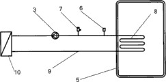
Fig. 4 is for being used in the excessive low water level protection device of water fluorine heat exchanger water circulation system the connection diagram of separated type solar water heater.
Fig. 5 is the excessive low water level protection device connection diagram of water circulation system in the prior art;
The reference numeral explanation
1-water fluorine group of switches; 2-water fluorine heat exchanger; The 3-water pump; The 4-flow switch; The 5-water tank; The 6-pressure switch; The 7-automatic exhaust steam valve; The 8-coil pipe; The 9-pipeline; 10-solar energy heating plate.
The specific embodiment
Come to specify the excessive low water level protection device of the water circulation system that the utility model provides by specific embodiment below in conjunction with figure.
Embodiment 1:
Below, be that example describes the utility model to utilize heat pump techniques to produce the water fluorine heat exchanger that hot water uses.
The connection diagram of the excessive low water level protection device embodiment 1 of the water fluorine heat exchanger water circulation system that Fig. 1 provides for the utility model, the excessive low water level protection device of water fluorine heat exchanger 2 has pipeline 9 and water pump 3 as shown in the figure, and pipeline 9 is connected on the two ends up and down of water tank 5.Described water pump 3 flows water in described pipeline 9, in described pipeline 9 pressure switch 6 is set also, and this pressure switch 6 constitutes pressure detector and controller.The electric contact of this pressure switch 6 can directly be serially connected in the current supply circuit of described water pump 3, can also be serially connected in the current supply circuit of described water pump 3 by the relay (not shown), controls the running of described water pump 3.During water pump 3 runnings, the water in the water tank 5 flows in pipeline 9, generates hot water with the refrigerant generation heat exchange of flowing in the refrigerant pipeline in the water fluorine heat exchanger 2, thus the hot water in the continuous heating water tank 5.
No matter be before system's operation or pressure switch in service 6 is carried out pressure detecting to system all the time, too small or pipeline 9 keeped in repair can to occur pressure when cutting off the water too small or do not have pressure when hydraulic pressure in the pipeline 9, pressure switch 6 disconnects, and water pump 3 shuts down.The standard of the concrete force value of 6 foundations of pressure switch can be provided with according to the hydraulic pressure of Chinese municipal water supply in this process, as the hydraulic pressure of present municipal water supply at 0.3-0.4Mpa, pressure switch 6 can be set when the force value of system is lower than 0.05Mpa, disconnect, and when the force value of system reaches 0.15Mpa, recover cut-in pressure switch 6.
Also has automatic exhaust steam valve 7 in the excessive low water level protection device of water circulation system; automatic exhaust steam valve 7 is installed in the peak of water circulation system; can at any time and automatically intrasystem gas be discharged; be used with pressure switch 6, the two is in conjunction with guaranteeing that the hydraulic pressure in the described water circulation system meets the working range of pressure switch 6 constantly.Pressure detector in the pressure switch 6 detects the hydraulic pressure in the described pipeline 9, and when hydraulic pressure was lower than certain value, controller action disconnected pressure switch 6, and water pump 3 shuts down.
Water circulation system also has water tank 5, and water tank 5 is arranged in described pipeline 9, directly is attempted by the two ends of water fluorine group of switches 1 by pipeline 9, constitutes the part of described pipeline 9, can directly heat the water in the water tank 5.Water circulation system is to utilize heat pump techniques to produce the water fluorine heat exchanger 2 that hot water is used, and can protect water fluorine heat exchanger 2 to damage because of lack of water makes water pump 3.
The pipeline 9 of sealing and water pump 3 constitute closed circulating water system, are provided with the water compensating valve (not shown) in the pipeline 9 of sealing, in case lack of water can be passed through water compensating valve in the pipeline 9, moisturizing in pipeline 9 makes that water circulation system can long-time running.
Whether pressure by water detect lack of water, and detects by flow whether lack of water is compared, and the water pump 3 that need not turn round can detect, and has prevented that effectively water pump 3 from turning round under exsiccosis, and protection water pump 3 is avoided damaging.
Embodiment 2:
The connection diagram of the excessive low water level protection device embodiment 2 of the water circulation system that Fig. 2 provides for the utility model; as can be seen from the figure; the utility model is not done special qualification to 6 position of pressure switch; except as can being arranged in the pipeline 9 among the embodiment 1, pressure switch 6 can also be arranged at tank top.Pressure detector in the pressure switch 6 detects the hydraulic pressure in the described water tank 5, and when hydraulic pressure was lower than certain value, controller action disconnected pressure switch 6, and water pump 3 shuts down.
Embodiment 3:
The connection diagram of the excessive low water level protection device embodiment 3 of the water circulation system that Fig. 3 provides for the utility model; as can be seen from the figure; circulating water line 9 is the pipeline of sealing, and its part is arranged in the coil pipe 8 that water tank 5 forms as shown in Figure 4, isolates with the water maintenance in the water tank 5.Therefore the medium in the pipeline 9 can be different with the material of water tank 5, that is, can be other medium beyond dewatering in the pipeline 9, such as utilizing anti-icing fluid etc., enlarged the scope of utilizing.
The excessive low water level protection device of aforesaid water circulation system is not only applicable to utilize heat pump techniques to heat the water route circulation of water, is applicable to the closed circulation water road, burnt gas wall hanging furnace closed circulation water road of separated type solar heat hot water etc. yet.
The above only is preferred embodiment of the present utility model; not in order to restriction the utility model; all within spirit of the present utility model and principle; any modification of being done; be equal to replacement; improve etc.; the excessive low water level protection device that adds aforesaid water circulation system in the hot water cyclesystem in separated type solar for example shown in Figure 4 is protected water pump 3; at this moment; described pipeline 9 forms the loop in solar energy heating plate 10; its two ends are connected with coil pipe 8 in the water tank 5; during water pump 3 work; water circulates in pipeline 9 and coil pipe 8, with the thermal energy transfer of the sun in water tank 8.Pressure detector in the pressure switch 6 detects the hydraulic pressure in the described pipeline 9, and when hydraulic pressure was lower than certain value, described controller action disconnected pressure switch 6, and described water pump 3 shuts down and protects water pump 3.
All should be included within the protection domain of the present utility model.
Claims (6)
1. the water pump that the excessive low water level protection device of a water circulation system, described water circulation system have pipeline and water is flowed in described pipeline is characterized in that, in described pipeline, be provided with the pressure detector that detects the hydraulic pressure in the described pipeline and
When being lower than certain value, hydraulic pressure controls the controller that described water pump shuts down.
2. according to the excessive low water level protection device of the water circulation system of claim 1, it is characterized in that described pressure detector and controller are made of pressure switch, the electric contact of this pressure switch directly or be serially connected in by relay in the current supply circuit of described water pump.
3. according to the excessive low water level protection device of the water circulation system of claim 1, it is characterized in that described water circulation system is a closed circulating water system, constitute, in the pipeline of sealing, be provided with water compensating valve by the pipeline and the water pump of sealing.
4. according to the excessive low water level protection device of the water circulation system of claim 3, it is characterized in that having water tank, described water tank is arranged in described pipeline, constitutes the part of described pipeline.
5. according to the excessive low water level protection device of the water circulation system of claim 3, it is characterized in that having water tank, described pipeline is the pipeline of sealing, and its part is arranged in described water tank.
6. according to the excessive low water level protection device of the water circulation system of claim 4 or 5, it is characterized in that described water circulation system is to utilize heat pump techniques to produce the water fluorine heat exchanger that hot water is used.
Priority Applications (1)
| Application Number | Priority Date | Filing Date | Title |
|---|---|---|---|
| CN2011200941609U CN202092316U (en) | 2011-03-29 | 2011-03-29 | Water shortage protecting device of water circulating system |
Applications Claiming Priority (1)
| Application Number | Priority Date | Filing Date | Title |
|---|---|---|---|
| CN2011200941609U CN202092316U (en) | 2011-03-29 | 2011-03-29 | Water shortage protecting device of water circulating system |
Publications (1)
| Publication Number | Publication Date |
|---|---|
| CN202092316U true CN202092316U (en) | 2011-12-28 |
Family
ID=45367383
Family Applications (1)
| Application Number | Title | Priority Date | Filing Date |
|---|---|---|---|
| CN2011200941609U Expired - Fee Related CN202092316U (en) | 2011-03-29 | 2011-03-29 | Water shortage protecting device of water circulating system |
Country Status (1)
| Country | Link |
|---|---|
| CN (1) | CN202092316U (en) |
Cited By (1)
| Publication number | Priority date | Publication date | Assignee | Title |
|---|---|---|---|---|
| CN102162683A (en) * | 2011-03-29 | 2011-08-24 | 海尔集团公司 | Water shortage protection device of water circulation system |
-
2011
- 2011-03-29 CN CN2011200941609U patent/CN202092316U/en not_active Expired - Fee Related
Cited By (1)
| Publication number | Priority date | Publication date | Assignee | Title |
|---|---|---|---|---|
| CN102162683A (en) * | 2011-03-29 | 2011-08-24 | 海尔集团公司 | Water shortage protection device of water circulation system |
Similar Documents
| Publication | Publication Date | Title |
|---|---|---|
| CN202644252U (en) | Steam iron remnant steam and residual heat recovery device | |
| CN102162683A (en) | Water shortage protection device of water circulation system | |
| CN202885240U (en) | Heat pump hot water unit with anti-freezing pipelines | |
| CN104848295A (en) | Self-adaption intelligent heat exchange station | |
| CN204100576U (en) | A kind of air-source water heater water system | |
| CN104848294A (en) | High-temperature-water heat exchange low-temperature-water direct connection heating system | |
| CN103034221B (en) | thermal power plant circulating water system | |
| CN101839520B (en) | Solar-powered-air source heat-pump composite water heating system and control method thereof | |
| CN202092316U (en) | Water shortage protecting device of water circulating system | |
| CN202562032U (en) | Circulation and direct heating integration heat pump hot-water machine set | |
| CN203489495U (en) | Solar energy and ground source heat pump combined hot water supplying system | |
| CN104848383A (en) | Self-adaption intelligent energy-saving heat exchange station | |
| CN201973778U (en) | Solar heating and domestic hot water supplying integrated system | |
| CN103256716B (en) | Method and device for recovering retention heat of gas heating water heater | |
| CN206071749U (en) | A kind of marine generator waste heat cyclic utilization system | |
| CN205156210U (en) | Take auxiliary cold source's ocean refrigerated water concentrated cooling system | |
| CN104848287A (en) | Steam condensate water waste heat utilizing and recycling device of heat exchange station | |
| CN203413718U (en) | Boiler heat supply system with high-temperature hot water boiler return water temperature raising function | |
| CN206430250U (en) | Solar energy combines heating plant with gas-heating water heater | |
| CN207642005U (en) | Hot-rolling mill lotion heating control system | |
| CN201680501U (en) | Recovery device of steam condensate | |
| CN105240970A (en) | Sea-chilled-water concentrated cold supplying system with auxiliary cold source and concentrated cold supplying method | |
| CN105222342A (en) | Enhanced heat exchange formula heat pump | |
| CN205002395U (en) | Civil boiler water circulating system | |
| CN201680573U (en) | Anti-electric shock heat-storage type hot water system |
Legal Events
| Date | Code | Title | Description |
|---|---|---|---|
| C14 | Grant of patent or utility model | ||
| GR01 | Patent grant | ||
| CF01 | Termination of patent right due to non-payment of annual fee |
Granted publication date: 20111228 Termination date: 20170329 |
|
| CF01 | Termination of patent right due to non-payment of annual fee |