CN202071291U - Multi-cavity elbow moulding mould - Google Patents
Multi-cavity elbow moulding mould Download PDFInfo
- Publication number
- CN202071291U CN202071291U CN2011201221412U CN201120122141U CN202071291U CN 202071291 U CN202071291 U CN 202071291U CN 2011201221412 U CN2011201221412 U CN 2011201221412U CN 201120122141 U CN201120122141 U CN 201120122141U CN 202071291 U CN202071291 U CN 202071291U
- Authority
- CN
- China
- Prior art keywords
- mould
- elbow
- plate
- core
- cavity
- Prior art date
- Legal status (The legal status is an assumption and is not a legal conclusion. Google has not performed a legal analysis and makes no representation as to the accuracy of the status listed.)
- Expired - Fee Related
Links
Images
Abstract
A multi-cavity moulding mould comprises an upper plate and a lower plate. The upper plate is connected with a fixed mould plate. The lower plate is provided with a mould foot inside which a top plate is arranged. An ejector rod is connected with the top plate. A movable mould plate is arranged on the mould foot and a mould core is arranged in the movable mould plate. The outside of the mould core is provided with an elbow. The multi-cavity elbow moulding mould is characterized in that the movable mould plate is provided with a core-pulling insert block where an oblique slide is arranged. An oblique slide block is arranged on the oblique slide. The oblique slide block is provided with an oblique guide hole. An oblique guide column is connected with the lower portion of the lower plate. The oblique guide column penetrates the oblique guide hole. The inner wall of the slide block is connected with the core-pulling core which is in contact with the inner wall of the elbow. The core-pulling core is provided with a press plate connected with a filling block where an R-angle mould cavity is arranged. The R-angle mould cavity is in contact with the outer wall of the opening position of the elbow. A certain demoulding space is reserved for the filling block after demoulding of the oblique slide block so that the R angle is led to be smoothly separated from the opening position of the elbow, thereby realizing production of the multi-cavity elbow, reducing cost and improving product quality.
Description
Technical field
The utility model relates to a kind of multi-cavity bend forming mould, belongs to the mould of plastics field.
Background technology
Adopt injection mold to produce plastic product, for example plastic elbow pipe fitting etc. in order to enhance productivity, generally all adopts a multi-cavity mold processing.But prior art can not be done the R angle at the oral area outer wall of elbow owing to be subjected to the restriction of multi-cavity mold structure, easy to use when having influenced the good looking appearance of product and assembling.
Summary of the invention
The purpose of this utility model is in order to overcome the shortcoming of prior art, to provide a kind of simple in structure, and cost is low, can realize the multi-cavity bend forming mould of elbow oral area outer wall R angle processing.
The technical scheme of the utility model multi-cavity bend forming mould is: comprise upper mould plate and lower bolster, cope match-plate pattern connects solid plate, the mould pin is installed on the lower bolster, in the mould pin top board is set, connect push rod on the top board, on the mould pin moving platen is installed, core is installed in the moving platen, core has elbow outward, it is characterized in that installing to loose core on the described moving platen inserting, loosing core is shaped on inclined ramp on inserting, and angled-lift splits is set on the inclined ramp, is shaped on oblique guide hole in the angled-lift splits, cope match-plate pattern connects Angle Pin down, Angle Pin passes oblique guide hole, and the inwall of described angled-lift splits connects the fuse of loosing core, and the fuse of loosing core contacts with elbow interior wall, the fuse of loosing core has pressing plate, pressing plate connects cushion block, is shaped on R angle die cavity on the cushion block, and R angle die cavity contacts with elbow oral area outer wall.
Multi-cavity bend forming mould of the present utility model adopts Angle Pin and angled-lift splits fit system, utilizes mould open/close mould power, and Angle Pin drives the angled-lift splits slip and looses core, and need not to put in addition power, and cost is economized.Outside the fuse of loosing core, be equipped with pressing plate, pressing plate connects cushion block, be shaped on R angle die cavity in the cushion block, R angle die cavity contacts with elbow oral area outer wall, and the R angle in cushion block, can be provided the certain demoulding space of cushion block after the angled-lift splits demoulding, the R angle is broken away from from elbow oral area outer wall smoothly, realize the production of multi-cavity elbow, reduced cost, improved product quality.
Multi-cavity bend forming mould of the present utility model, the both sides of described angled-lift splits are equipped with press strip, and press strip is pushed down angled-lift splits, prevents that angled-lift splits from coming off.
Description of drawings
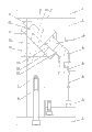
Fig. 1 is a multi-cavity bend forming mould structure schematic diagram of the present utility model;
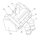
Fig. 2 is a multi-cavity bend forming mould schematic perspective view of the present utility model.
The specific embodiment
The utility model relates to a kind of multi-cavity bend forming mould, as Fig. 1, shown in Figure 2, comprise upper mould plate 1 and lower bolster 2, cope match-plate pattern 1 connects solid plate 3, and mould pin 4 is installed on the lower bolster 2, and top board 5 is set in the mould pin, connect push rod 6 on the top board, moving platen 7 is installed on the mould pin, core 8 is installed in the moving platen 7, elbow 9 is arranged outside the core 8, it is characterized in that installing to loose core on the described moving platen 7 inserting 10, loosing core inserts is shaped on inclined ramp 11 on 10, and angled-lift splits 12 is set on the inclined ramp, is shaped on oblique guide hole in the angled-lift splits, cope match-plate pattern connects Angle Pin 13 1 time, Angle Pin 13 passes oblique guide hole, and the inwall of described angled-lift splits 12 connects the fuse 14 of loosing core, and the fuse 14 of loosing core contacts with elbow 9 inwalls, the fuse 9 of loosing core has pressing plate 15, pressing plate 15 connects cushion block 16, is shaped on R angle die cavity 17 on the cushion block 16, and R angle die cavity 17 contacts with elbow 9 oral area outer walls.This programme adopts Angle Pin 13 and angled-lift splits 12 fit systems, utilizes mould open/close mould power, and Angle Pin 13 drives angled-lift splits 12 slips and looses core, and need not to put in addition power, and cost is economized.Outside the fuse 14 of loosing core, be equipped with pressing plate 15, pressing plate 15 connects cushion block 16, be shaped on R angle die cavity 17 in the cushion block 16, R angle die cavity 17 contacts with elbow 9 oral area outer walls, and the R angle in 16 on pad, can be provided the certain demoulding space of cushion block 16 after angled-lift splits 12 demouldings, the R angle is broken away from from elbow 9 oral area outer walls smoothly, realize the production of multi-cavity elbow, reduced cost, improved product quality.The both sides of described angled-lift splits 12 are equipped with press strip 18, and press strip is pushed down angled-lift splits, prevent that angled-lift splits from coming off.
Claims (2)
1. multi-cavity bend forming mould, comprise upper mould plate (1) and lower bolster (2), cope match-plate pattern (1) connects solid plate (3), lower bolster (2) is gone up mould pin (4) is installed, top board (5) is set in the mould pin, connect push rod (6) on the top board, moving platen (7) is installed on the mould pin, core (8) is installed in the moving platen (7), core (8) is outer elbow (9), it is characterized in that described moving platen (7) is gone up insert (10) of loosing core are installed, and loosing core inserts is shaped on inclined ramp (11) on (10), angled-lift splits (12) is set on the inclined ramp, be shaped on oblique guide hole in the angled-lift splits, cope match-plate pattern (1) connects Angle Pin (13) down, and Angle Pin (13) passes oblique guide hole, the inwall of described angled-lift splits (12) connects the fuse (14) of loosing core, the fuse (14) of loosing core contacts with elbow (9) inwall, and the fuse of loosing core (9) has pressing plate (15), and pressing plate (15) connects cushion block (16), be shaped on R angle die cavity (17) on the cushion block (16), R angle die cavity (17) contacts with elbow (9) oral area outer wall.
2. multi-cavity bend forming mould as claimed in claim 1 is characterized in that the both sides of described angled-lift splits (12) are equipped with press strip (18).
Priority Applications (1)
| Application Number | Priority Date | Filing Date | Title |
|---|---|---|---|
| CN2011201221412U CN202071291U (en) | 2011-04-25 | 2011-04-25 | Multi-cavity elbow moulding mould |
Applications Claiming Priority (1)
| Application Number | Priority Date | Filing Date | Title |
|---|---|---|---|
| CN2011201221412U CN202071291U (en) | 2011-04-25 | 2011-04-25 | Multi-cavity elbow moulding mould |
Publications (1)
| Publication Number | Publication Date |
|---|---|
| CN202071291U true CN202071291U (en) | 2011-12-14 |
Family
ID=45109400
Family Applications (1)
| Application Number | Title | Priority Date | Filing Date |
|---|---|---|---|
| CN2011201221412U Expired - Fee Related CN202071291U (en) | 2011-04-25 | 2011-04-25 | Multi-cavity elbow moulding mould |
Country Status (1)
| Country | Link |
|---|---|
| CN (1) | CN202071291U (en) |
Cited By (3)
| Publication number | Priority date | Publication date | Assignee | Title |
|---|---|---|---|---|
| CN106217784A (en) * | 2016-08-31 | 2016-12-14 | 台州市黄岩炜大塑料机械有限公司 | 45 ° of elbow member mould entirety are floated and are tiltedly slipped mold mechanism |
| CN109702969A (en) * | 2019-02-21 | 2019-05-03 | 台州市黄岩炜大塑料机械有限公司 | Odd test demolding structure is straightened in big bent pipe fitting piece mold slanted |
| CN114789543A (en) * | 2022-05-06 | 2022-07-26 | 台州市黄岩炜大塑料机械有限公司 | Injection mold for precise double-bellmouth 45-degree bent pipe fitting |
-
2011
- 2011-04-25 CN CN2011201221412U patent/CN202071291U/en not_active Expired - Fee Related
Cited By (4)
| Publication number | Priority date | Publication date | Assignee | Title |
|---|---|---|---|---|
| CN106217784A (en) * | 2016-08-31 | 2016-12-14 | 台州市黄岩炜大塑料机械有限公司 | 45 ° of elbow member mould entirety are floated and are tiltedly slipped mold mechanism |
| CN109702969A (en) * | 2019-02-21 | 2019-05-03 | 台州市黄岩炜大塑料机械有限公司 | Odd test demolding structure is straightened in big bent pipe fitting piece mold slanted |
| CN109702969B (en) * | 2019-02-21 | 2023-12-29 | 台州市黄岩炜大塑料机械有限公司 | Inclined-pulling drawing type demoulding structure of large-bridge bent pipe fitting mould |
| CN114789543A (en) * | 2022-05-06 | 2022-07-26 | 台州市黄岩炜大塑料机械有限公司 | Injection mold for precise double-bellmouth 45-degree bent pipe fitting |
Similar Documents
| Publication | Publication Date | Title |
|---|---|---|
| CN201755897U (en) | Inclined slide type secondary core drawing mechanism of injection mould | |
| CN104526981A (en) | Secondary die opening slide block internal pulling mechanism of junction box die | |
| CN203567094U (en) | Translation oblique-push core-pulling mechanism of injection mold angular pin sliders | |
| CN202985965U (en) | Injection mold for automobile lampshade | |
| CN202071291U (en) | Multi-cavity elbow moulding mould | |
| CN204546940U (en) | Pulling mechanism in terminal box mould secondary die sinking slide block | |
| CN103538211B (en) | Die sinking both direction core-pulling mechanism | |
| CN202011093U (en) | Oblique ejection and side popping device of plastic die | |
| CN203293487U (en) | Flexible pipe plug injection mold | |
| CN102328366B (en) | Four-way flared tube joint mould demoulding mechanism | |
| CN201889884U (en) | Secondary core-pulling mechanism for automobile grating reverse sensor mounting holes | |
| CN203557644U (en) | Slider demoulding structure for injection mould | |
| CN103029236A (en) | Four-matrix mold structure | |
| CN203637105U (en) | Mould for ejecting plastic products by virtue of dovetail slot and spring mechanism | |
| CN201784103U (en) | Secondary core-pulling mechanism for inclined guide pillar of base mould of automobile headlamp | |
| CN202727249U (en) | Plastic mold | |
| CN202029332U (en) | External bracing demoulding mechanism of automobile bumper injection mould | |
| CN103909630B (en) | Ejector sleeve ejecting mechanism | |
| CN207172649U (en) | A kind of switch panel injection mold | |
| CN206230824U (en) | The multi-direction reverse buckle demolding mechanism of injection mold plastic | |
| CN205969748U (en) | Integrative mould of five metals plastic | |
| CN201960708U (en) | Core pulling mechanism for positioning ejection block of injection mold | |
| CN103640191A (en) | Mechanism for separating plastic products from slide blocks on four sides | |
| CN2923266Y (en) | Mould structure | |
| CN202781724U (en) | Novel secondary ejecting mechanism |
Legal Events
| Date | Code | Title | Description |
|---|---|---|---|
| C14 | Grant of patent or utility model | ||
| GR01 | Patent grant | ||
| CF01 | Termination of patent right due to non-payment of annual fee | ||
| CF01 | Termination of patent right due to non-payment of annual fee |
Granted publication date: 20111214 Termination date: 20200425 |