CN202064255U - Novel floor - Google Patents

Novel floor Download PDF

Info

Publication number
CN202064255U
CN202064255U CN2011200963665U CN201120096366U CN202064255U CN 202064255 U CN202064255 U CN 202064255U CN 2011200963665 U CN2011200963665 U CN 2011200963665U CN 201120096366 U CN201120096366 U CN 201120096366U CN 202064255 U CN202064255 U CN 202064255U
Authority
CN
China
Prior art keywords
floor
hole
chute
shaped
installation
Prior art date
Legal status (The legal status is an assumption and is not a legal conclusion. Google has not performed a legal analysis and makes no representation as to the accuracy of the status listed.)
Expired - Fee Related
Application number
CN2011200963665U
Other languages
Chinese (zh)
Inventor
施迎春
卢娟
施迎梅
施竹君
Current Assignee (The listed assignees may be inaccurate. Google has not performed a legal analysis and makes no representation or warranty as to the accuracy of the list.)
HUZHOU MEIDIAN NEW MATERIAL CO Ltd
Original Assignee
HUZHOU MEIDIAN NEW MATERIAL CO Ltd
Priority date (The priority date is an assumption and is not a legal conclusion. Google has not performed a legal analysis and makes no representation as to the accuracy of the date listed.)
Filing date
Publication date
Application filed by HUZHOU MEIDIAN NEW MATERIAL CO Ltd filed Critical HUZHOU MEIDIAN NEW MATERIAL CO Ltd
Priority to CN2011200963665U priority Critical patent/CN202064255U/en
Application granted granted Critical
Publication of CN202064255U publication Critical patent/CN202064255U/en
Anticipated expiration legal-status Critical
Expired - Fee Related legal-status Critical Current

Links

Images

Classifications

    • Y—GENERAL TAGGING OF NEW TECHNOLOGICAL DEVELOPMENTS; GENERAL TAGGING OF CROSS-SECTIONAL TECHNOLOGIES SPANNING OVER SEVERAL SECTIONS OF THE IPC; TECHNICAL SUBJECTS COVERED BY FORMER USPC CROSS-REFERENCE ART COLLECTIONS [XRACs] AND DIGESTS
    • Y02—TECHNOLOGIES OR APPLICATIONS FOR MITIGATION OR ADAPTATION AGAINST CLIMATE CHANGE
    • Y02A—TECHNOLOGIES FOR ADAPTATION TO CLIMATE CHANGE
    • Y02A30/00—Adapting or protecting infrastructure or their operation
    • Y02A30/60—Planning or developing urban green infrastructure

Landscapes

  • Floor Finish (AREA)

Abstract

本实用新型公开了一种新型地板,包括本体,本体包括底面和顶面,本体的两侧设有安装用的滑槽,本体中设有通孔,通孔包括有“8”字形通孔,“8”字形通孔分布在邻近滑槽一侧,“8”字形通孔之间设有方形通孔,滑槽的顶边向上倾斜,滑槽的底边向下倾斜,滑槽呈梯形状,本体的顶面均匀设有若干凹槽,各凹槽之间相互平行,本体的底面为光滑平面,本体采用木塑材料制成。本实用新型大大减小了地板的用材,同时“8”字形通孔可以减小地板的内应力,有效避免地板地变形、开裂等情况,增强了地板的承受力,保证地板的质量;另外地板安装简便,连接简单、可靠,也可以实现地板地重复利用,且地板安装完成后形成的整体墙面外形美观。

Figure 201120096366

The utility model discloses a novel floor, which comprises a body. The body includes a bottom surface and a top surface. The two sides of the body are provided with sliding grooves for installation. The body is provided with a through hole. The through hole includes an "8"-shaped through hole. The "8"-shaped through holes are distributed on one side of the adjacent chute, and there are square through holes between the "8"-shaped through holes. The top edge of the chute is inclined upward, and the bottom edge of the chute is inclined downward. The chute is trapezoidal. The top surface of the main body is evenly provided with several grooves, and the grooves are parallel to each other. The bottom surface of the main body is a smooth plane, and the main body is made of wood-plastic material. The utility model greatly reduces the material used for the floor, and at the same time, the "8"-shaped through hole can reduce the internal stress of the floor, effectively avoid the deformation and cracking of the floor, enhance the bearing capacity of the floor, and ensure the quality of the floor; The installation is simple, the connection is simple and reliable, and the floor can also be reused, and the overall wall surface formed after the floor installation is completed has a beautiful appearance.

Figure 201120096366

Description

A kind of novel floor
Technical field
The utility model relates to the floor that a kind of garden landscape is used.
Background technology
Common floor is generally solid, and whole the rectangular-shaped of rule that be.The employing said structure has the following disadvantages: one, solid floor, and consumptive material is many, the cost of production height; Two, need to adopt multiple instrument just can finish the installation on floor, install inconvenient; Three, can't move again after the installation of floor, dismantle, can only carry out the shakedown dismounting, can't reuse.
The utility model content
The purpose of this utility model is to provide a kind of novel floor, and it is big to solve existing solid flooring material consumption effectively, and weight is big, and the problem of inconvenience is installed.
In order to solve the problems of the technologies described above, the utility model adopts following technical scheme: a kind of novel floor, comprise body, body comprises bottom surface and end face, it is characterized in that: the both sides of body are provided with the chute that usefulness is installed, be provided with through hole in the body, through hole includes figure of eight through hole, and figure of eight through hole is distributed in contiguous chute one side.
Further, be provided with square through hole between the figure of eight through hole, save material, process easy.
Preferably, the top margin of chute is inclined upwardly, and the base of chute is downward-sloping, and chute is trapezoidal shape, can guarantee bonding strength and reliability, effectively avoids producing relative motion between each floor, guarantees the installation quality on floor.
Further, the end face of body evenly is provided with some grooves, is parallel to each other between each groove, and groove has increased the frictional force of floor surface, is not easy to skid, and simultaneously groove can play the water guide effect, when effectively avoiding the rainy day on the floor ponding.
Further, the bottom surface of body is a smooth flat, guarantees the smooth of floor, avoids producing injustice, influences the quality on floor.
Preferably, body adopts Wood-plastic material to make, and is corrosion-resistant, long service life.
The utility model is owing to adopted technique scheme, reduced the material of using on floor greatly, the floor body boring, reduced cost of production, and hollow floor has alleviated the weight on floor, and figure of eight through hole can reduce the internal stress on floor simultaneously, effectively avoids situations such as floor ground distortion, cracking, strengthen the holding capacity on floor, guaranteed the quality on floor; Floor simple installation in addition, be slidingly connected on the default slide rail in the chute between adjacent two floors, can realize installing, connect simple, reliable, can each floor there be destructive dismounting yet, easy and simple to handle, realize the recycling of ground, floor, and the whole metope good looking appearance that forms after the installation of floor.The utility model is simple in structure, manufacturing is easy, cost is low, practical.
Description of drawings
The utility model is described in further detail below in conjunction with accompanying drawing:
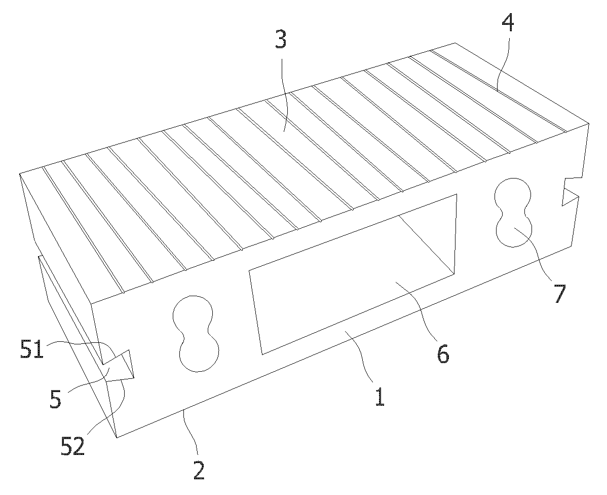
Fig. 1 is the structural representation of a kind of novel floor of the utility model.
The specific embodiment
As shown in Figure 1, for a kind of novel floor of the utility model, comprise body 1, body 1 adopts Wood-plastic material to make, and is corrosion-resistant, long service life.Body 1 comprises bottom surface 2 and end face 3, the both sides of body 1 are provided with the chute 5 that usefulness is installed, be provided with through hole 6 in the body 1, through hole 6 includes " 8 " font through hole 7; " 8 " font through hole 7 is distributed in contiguous chute 5 one sides; " 8 " be provided with square through hole 6 between the font through hole 7; save material; process easyly, the top margin 51 of chute 5 is inclined upwardly, and the base 52 of chute 5 is downward-sloping; chute 5 is trapezoidal shape; can guarantee bonding strength and reliability, effectively avoids producing relative motion between each floor the installation quality on assurance floor.The end face 3 of body 1 evenly is provided with some grooves 4, be parallel to each other between each groove 4, groove 4 has increased the frictional force of floor surface, be not easy to skid, simultaneously groove 4 can play the water guide effect, when effectively avoiding the rainy day on the floor ponding, the bottom surface 2 of body 1 is a smooth flat, guarantee the smooth of floor, avoid producing injustice, influence the quality on floor.

Claims (6)

1. novel floor, comprise body (1), described body (1) comprises bottom surface (2) and end face (3), it is characterized in that: the both sides of described body (1) are provided with the chute (5) that usefulness is installed, described body is provided with through hole in (1), described through hole includes " 8 " font through hole (7), described " 8 " font through hole (7) is distributed in contiguous chute (5) one sides.
2. a kind of novel floor according to claim 1 is characterized in that: described " 8 " be provided with square through hole (6) between the font through hole (7).
3. a kind of novel floor according to claim 1 and 2 is characterized in that: the top margin (51) of described chute (5) is inclined upwardly, and the base (52) of described chute (5) is downward-sloping, and described chute (5) is trapezoidal shape.
4. a kind of novel floor according to claim 1 and 2 is characterized in that: the end face (3) of described body (1) evenly is provided with some grooves (4), is parallel to each other between described each groove (4).
5. a kind of novel floor according to claim 1 and 2 is characterized in that: the bottom surface (2) of described body (1) is a smooth flat.
6. a kind of novel floor according to claim 1 is characterized in that: described body (1) adopts Wood-plastic material to make.
CN2011200963665U 2011-04-02 2011-04-02 Novel floor Expired - Fee Related CN202064255U (en)

Priority Applications (1)

Application Number Priority Date Filing Date Title
CN2011200963665U CN202064255U (en) 2011-04-02 2011-04-02 Novel floor

Applications Claiming Priority (1)

Application Number Priority Date Filing Date Title
CN2011200963665U CN202064255U (en) 2011-04-02 2011-04-02 Novel floor

Publications (1)

Publication Number Publication Date
CN202064255U true CN202064255U (en) 2011-12-07

Family

ID=45058121

Family Applications (1)

Application Number Title Priority Date Filing Date
CN2011200963665U Expired - Fee Related CN202064255U (en) 2011-04-02 2011-04-02 Novel floor

Country Status (1)

Country Link
CN (1) CN202064255U (en)

Cited By (3)

* Cited by examiner, † Cited by third party
Publication number Priority date Publication date Assignee Title
CN108394057A (en) * 2018-01-24 2018-08-14 河南工程学院 A kind of preparation method of wood moulding floor tile for gardens pavement
US20190288638A1 (en) * 2018-03-15 2019-09-19 The Boeing Company Rollable solar power module with high packing density
US11257969B2 (en) 2018-03-15 2022-02-22 The Boeing Company Blocking diode board for rollable solar power module

Cited By (4)

* Cited by examiner, † Cited by third party
Publication number Priority date Publication date Assignee Title
CN108394057A (en) * 2018-01-24 2018-08-14 河南工程学院 A kind of preparation method of wood moulding floor tile for gardens pavement
US20190288638A1 (en) * 2018-03-15 2019-09-19 The Boeing Company Rollable solar power module with high packing density
US11257969B2 (en) 2018-03-15 2022-02-22 The Boeing Company Blocking diode board for rollable solar power module
US11817514B2 (en) 2018-03-15 2023-11-14 The Boeing Company Blocking diode board for rollable solar power module

Similar Documents

Publication Publication Date Title
CN201972369U (en) Floor
CN201972368U (en) Floor board
CN101403252A (en) Hanging cradle for inner wall construction of chimney or well
CN202073251U (en) Novel armrest
CN203924623U (en) The ferropectic baseboard assembly of a kind of employing magnetic
CN204673961U (en) The short mold insert pitched roof mechanism of a kind of long push rod
CN201972330U (en) Handrail
CN202064552U (en) Wall protection plate
CN201833520U (en) Sloping top core extracting structure
CN202012179U (en) Splicing structure for floorboard
CN202371087U (en) Floating sliding-clamped floor shock-absorption device of train
CN201924460U (en) Perpendicular section steel mechanism for steel structures
CN202055484U (en) Wood plastic floor
CN202899607U (en) Construction engineering aluminum formwork
CN218541484U (en) External hanging template
CN202650553U (en) Surface mounted instrument board which can be assembled and disassembled easily
CN202892914U (en) Dismantled-type toy bucket
CN202390928U (en) Grid structure
CN201952906U (en) Oblique profile steel mechanism for steel structure
CN201972266U (en) Novel shear wall
CN202152492U (en) Fixing mechanism used for steel structure
CN202543958U (en) Foot margin used for steel structure building
CN203112300U (en) Elevator sill
CN202370092U (en) Slant middle beam column for steel structure
CN202227692U (en) Middle transverse diaphragm plate used for box-girder external moulds

Legal Events

Date Code Title Description
C14 Grant of patent or utility model
GR01 Patent grant
CF01 Termination of patent right due to non-payment of annual fee

Granted publication date: 20111207

Termination date: 20160402

CF01 Termination of patent right due to non-payment of annual fee