CN202052841U - Aluminium-alloy grooving and blanking mold - Google Patents
Aluminium-alloy grooving and blanking mold Download PDFInfo
- Publication number
- CN202052841U CN202052841U CN2011201230996U CN201120123099U CN202052841U CN 202052841 U CN202052841 U CN 202052841U CN 2011201230996 U CN2011201230996 U CN 2011201230996U CN 201120123099 U CN201120123099 U CN 201120123099U CN 202052841 U CN202052841 U CN 202052841U
- Authority
- CN
- China
- Prior art keywords
- stamping
- moving knife
- section bar
- chopping block
- punching
- Prior art date
- Legal status (The legal status is an assumption and is not a legal conclusion. Google has not performed a legal analysis and makes no representation as to the accuracy of the status listed.)
- Expired - Fee Related
Links
- 229910000838 Al alloy Inorganic materials 0.000 title claims abstract description 22
- 238000004080 punching Methods 0.000 claims abstract description 121
- 230000007935 neutral effect Effects 0.000 claims abstract description 17
- 238000003825 pressing Methods 0.000 abstract description 8
- 238000007789 sealing Methods 0.000 abstract 2
- 238000010586 diagram Methods 0.000 description 10
- 238000000034 method Methods 0.000 description 3
- 238000005516 engineering process Methods 0.000 description 2
- 238000001125 extrusion Methods 0.000 description 2
- 230000000694 effects Effects 0.000 description 1
- 238000003754 machining Methods 0.000 description 1
- 238000004519 manufacturing process Methods 0.000 description 1
- 239000000463 material Substances 0.000 description 1
- 238000012986 modification Methods 0.000 description 1
- 230000004048 modification Effects 0.000 description 1
- 238000010079 rubber tapping Methods 0.000 description 1
- XLYOFNOQVPJJNP-UHFFFAOYSA-N water Substances O XLYOFNOQVPJJNP-UHFFFAOYSA-N 0.000 description 1
Images




Landscapes
- Perforating, Stamping-Out Or Severing By Means Other Than Cutting (AREA)
Abstract
The utility model discloses an aluminium-alloy grooving and blanking mold, comprising a machine body. The machine body is provided with an installing board of a chopping board; a movable knife installing board is arranged above the installing board of the chopping board; a guide column is arranged between the movable knife installing board and the machine body; a pressing rod is hinged on the machine body; a hinged rod is arranged between the pressing rod and the movable knife installing board; the two ends of the hinged rod are respectively hinged on the pressing rod and the movable knife installing rod; an elastic resetting device is arranged between the movable knife installing board and the machine body; a guanggouqi profile groove blanking movable-knife and chopping-knife group, a guanggouqi profile clapboard blanking movable-knife and chopping-knife group, a guanggouqi profile punching movable-knife and chopping-knife group, an edge-sealing profile punching movable-knife and chopping-knife group, a downward-sliding water-draining hole blanking movable-knife and chopping-knife group, a neutral plugboard grooving and wing-board blanking movable-knife and chopping-knife group and an edge-sealing profile groove-board blanking movable-knife and chopping-knife group are arranged on the movable knife installing board and the installing board of the chopping board. In the aluminium-alloy grooving and blanking mold, the opening of groove holes and various blanking processing are realized on multiple profiles, the functions are rich, the efficiency is higher and the operation is convenient.
Description
Technical field
The utility model relates to a kind of fluting blanking die of aluminium alloy extrusions manufacture field.
Background technology
The aluminum alloy push-pull window profile comprises window frame profile and sash profile, window frame profile comprises banding, goes up cunning, downslide etc., sash profile comprises top, below, light hooked rabbet etc., in the process of process and assemble aluminum alloy push-pull window, often need on window frame profile and sash profile, slot, operation such as perforate, existing aluminium alloy extrusions fluting tapping equipment function singleness often needs different equipment just can finish processing in the use.
The utility model content
Technical problem to be solved in the utility model provides a kind ofly can carry out offering of multiple slotted eye, the aluminium alloy fluting blanking die that working (machining) efficiency is higher.
For solving the problems of the technologies described above, the technical solution of the utility model is: aluminium alloy fluting blanking die, comprise body, described body is provided with the chopping block installing plate, the top of described chopping block installing plate is provided with the moving knife installing plate, be provided with lead between described moving knife installing plate and the described body, be hinged with depression bar on the described body, be provided with hinge bar between described depression bar and the described moving knife installing plate, the two ends of described hinge bar are hinged on respectively on described depression bar and the described moving knife installing plate, be provided with elasticity reset device between described moving knife installing plate and the described body, described moving knife installing plate and described chopping block installing plate are provided with light hooked rabbet section bar groove stamping-out moving knife anvil cutter group, light hooked rabbet section bar dividing plate stamping-out moving knife anvil cutter group, light hooked rabbet section bar punching moving knife anvil cutter group, banding section bar punching moving knife anvil cutter group, gliding structural section dewatering orifice stamping-out moving knife anvil cutter group, neutral plate jet-bedding and wing plate stamping-out moving knife anvil cutter group, banding section bar frid stamping-out moving knife anvil cutter group.
As optimized technical scheme, described depression bar is hinged on the depression bar seat, and described depression bar seat is rotatably installed on the described body, and an end of described hinge bar is hinged with described depression bar, the other end of described hinge bar is hinged with dwang, and described dwang is rotatably installed on the described moving knife installing plate.
As optimized technical scheme, described smooth hooked rabbet section bar groove stamping-out moving knife chopping block group comprises groove stamping-out moving knife and groove stamping-out chopping block, described groove stamping-out moving knife is installed on the described moving knife installing plate, described groove stamping-out moving knife side surface is provided with the stamping-out sword, the lower surface of described groove stamping-out moving knife is provided with the section bar positioning convex, two lateral surfaces of described section bar positioning convex are fitted in the medial surface of light hooked rabbet section bar groove, described groove stamping-out chopping block is installed on the described chopping block installing plate, described groove stamping-out chopping block is provided with the stamping-out groove, and described stamping-out groove is corresponding with described groove stamping-out moving knife.
As optimized technical scheme, light hooked rabbet section bar dividing plate stamping-out moving knife chopping block group comprises dividing plate stamping-out moving knife and dividing plate stamping-out chopping block, described dividing plate stamping-out moving knife is fixedly mounted on the moving knife installing plate, described dividing plate stamping-out moving knife side surface is provided with the stamping-out sword, described dividing plate stamping-out chopping block is installed on the described chopping block installing plate, described dividing plate stamping-out chopping block upper surface is provided with the section bar detent, the outer end of described section bar detent is extended described dividing plate stamping-out anvil-shaped piece and is become section bar to insert mouth, the width of described section bar detent is corresponding with the width of light hooked rabbet section bar, two medial surfaces of described section bar detent are provided with the section bar support protrusion, described section bar support protrusion is supported in the side surface bottom of light hooked rabbet section bar, the section bar of described section bar detent is inserted the porch and is provided with the "T"-shaped section bar support that supports the location section bar, described "T"-shaped section bar support comprises horizontal location piece and the vertical locating piece that is installed together, the width of described horizontal location piece is corresponding to the width of light hooked rabbet section bar inner chamber, the width of described vertical locating piece is corresponding to the width of light hooked rabbet section bar groove, the upper end of described vertical locating piece is supported on the lower surface of described horizontal location piece, and the lower end of described vertical locating piece is fixedly mounted on the described chopping block installing plate.
As optimized technical scheme, described dividing plate stamping-out moving knife is stacked in described groove stamping-out moving knife upper surface.
As optimized technical scheme, light hooked rabbet section bar punching moving knife chopping block group comprises light hooked rabbet punching moving knife and light hooked rabbet punching chopping block, described smooth hooked rabbet punching moving knife is located on the described moving knife installing plate, described smooth hooked rabbet punching chopping block is installed on the chopping block installing plate, described smooth hooked rabbet punching chopping block stretches into light hooked rabbet section bar cavity, the width of described smooth hooked rabbet punching chopping block is corresponding to the width of described smooth hooked rabbet section bar cavity, and the upper surface of described smooth hooked rabbet punching chopping block is provided with and the corresponding punching of described smooth hooked rabbet punching moving knife.
As optimized technical scheme, banding section bar punching moving knife chopping block group comprises banding punching moving knife and banding punching chopping block, described banding punching moving knife is installed on the described moving knife installing plate, described banding punching chopping block is installed on the described chopping block installing plate, the spacing of at least one group of opposite side of described banding punching chopping block is corresponding to the width of banding section bar, and described punching chopping block is provided with and the corresponding punching of described banding punching moving knife.
As optimized technical scheme, described gliding structural section dewatering orifice stamping-out moving knife chopping block group comprises dewatering orifice stamping-out moving knife and dewatering orifice punching chopping block, described dewatering orifice stamping-out moving knife is fixedly mounted on the described moving knife installing plate, described dewatering orifice punching chopping block is fixedly mounted on the described chopping block installing plate, described dewatering orifice punching chopping block is provided with the punching groove, the side surface of recessed described dewatering orifice punching chopping block in the described punching groove, described punching groove upwards runs through the upper surface of described dewatering orifice punching chopping block.
As optimized technical scheme, described neutral plate jet-bedding and wing plate stamping-out moving knife anvil cutter group comprise wing plate stamping-out moving knife and wing plate stamping-out chopping block, described wing plate stamping-out moving knife is fixedly mounted on the moving knife installing plate, the left and right side of described wing plate stamping-out moving knife and outer end side surface are provided with initiatively stamping-out sword, the outer end side surface of described wing plate stamping-out moving knife is provided with the jet-bedding blade, described wing plate stamping-out chopping block is provided with the die-cut groove corresponding with described jet-bedding blade, and side surface corresponding with the outer end side surface of described wing plate stamping-out moving knife on the described wing plate stamping-out chopping block is provided with passive stamping-out sword.
As optimized technical scheme, described banding section bar frid stamping-out moving knife anvil cutter group comprises banding frid stamping-out moving knife and banding frid stamping-out chopping block, described banding frid stamping-out moving knife is fixedly mounted on the described moving knife installing plate, the left and right side of described banding frid stamping-out moving knife and outer end side surface are provided with the stamping-out sword, described banding frid stamping-out chopping block is installed on the described chopping block installing plate, described banding frid stamping-out chopping block is provided with section bar frid locating slot and section bar side plate locating slot, described section bar frid locating slot and described section bar side plate locating slot are opened in the side surface of described banding frid stamping-out chopping block, the frid of grafting gulde edge envelope section bar in the described section bar frid locating slot, the side plate of grafting gulde edge envelope section bar in the described section bar side plate locating slot, also be provided with frid stamping-out groove on the described banding frid stamping-out chopping block, described frid stamping-out groove recessed described frid stamping-out chopping block in the side surface that is provided with described section bar locating slot, described frid stamping-out groove upwards runs through described banding stamping-out chopping block upper surface, described frid stamping-out groove arrives described section bar side plate locating slot downwards and communicates with described section bar side plate locating slot, and described frid stamping-out groove is located at described frid stamping-out moving knife below.
Owing to adopted technique scheme, aluminium alloy fluting blanking die, comprise body, described body is provided with the chopping block installing plate, the top of described chopping block installing plate is provided with the moving knife installing plate, be provided with lead between described moving knife installing plate and the described body, be hinged with depression bar on the described body, be provided with hinge bar between described depression bar and the described moving knife installing plate, the two ends of described hinge bar are hinged on respectively on described depression bar and the described moving knife installing plate, be provided with elasticity reset device between described moving knife installing plate and the described body, described moving knife installing plate and described chopping block installing plate are provided with light hooked rabbet section bar groove stamping-out moving knife anvil cutter group, light hooked rabbet section bar dividing plate stamping-out moving knife anvil cutter group, light hooked rabbet section bar punching moving knife anvil cutter group, banding section bar punching moving knife anvil cutter group, downslide dewatering orifice stamping-out moving knife anvil cutter group, neutral plate jet-bedding and wing plate stamping-out moving knife anvil cutter group, banding section bar frid stamping-out moving knife anvil cutter group; Can realize offering and the processing of various stamping-out of slotted eye on multiple section bar, feature richness, efficient are higher, and easy to operate.
Description of drawings
Fig. 1, Fig. 2 are the structural representations of the utility model embodiment;
Fig. 3 is the structural representation of light hooked rabbet section bar groove stamping-out moving knife anvil cutter group among the utility model embodiment;
Fig. 4 is the operation principle schematic diagram that carries out the groove stamping-out of light hooked rabbet section bar groove stamping-out moving knife anvil cutter group among the utility model embodiment;
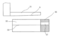
Fig. 5 is the structural representation of light hooked rabbet section bar dividing plate stamping-out moving knife anvil cutter group embodiment one among the utility model embodiment;
Fig. 6 is the operation principle schematic diagram that light hooked rabbet section bar dividing plate stamping-out moving knife anvil cutter group embodiment one carries out the dividing plate stamping-out among the utility model embodiment;
Fig. 7 is the structural representation of light hooked rabbet section bar dividing plate stamping-out moving knife anvil cutter group embodiment two among the utility model embodiment.
Fig. 8 is the operation principle schematic diagram that light hooked rabbet section bar dividing plate stamping-out moving knife anvil cutter group embodiment two carries out the groove stamping-out among the utility model embodiment;
Fig. 9 is the operation principle schematic diagram that light hooked rabbet section bar dividing plate stamping-out moving knife anvil cutter group embodiment two carries out the dividing plate stamping-out among the utility model embodiment;
Figure 10 is the structural representation of light hooked rabbet section bar punching moving knife anvil cutter group among the utility model embodiment;
Figure 11 is the operation principle schematic diagram of the punching processing of light hooked rabbet section bar punching moving knife anvil cutter group among the utility model embodiment;
Figure 12 is the structural representation of banding section bar punching moving knife anvil cutter group among the utility model embodiment;
Figure 13 is the operation principle schematic diagram that banding section bar punching moving knife anvil cutter group is carried out punching processing among the utility model embodiment;
Figure 14 is the side view of Figure 13;
Figure 15 is the structural representation of downslide dewatering orifice stamping-out moving knife anvil cutter group among the utility model embodiment;
Figure 16 is the operation principle schematic diagram that downslide dewatering orifice stamping-out moving knife anvil cutter group is carried out the dewatering orifice stamping-out among the utility model embodiment;
Figure 17 is the structural representation of neutral plate jet-bedding and wing plate stamping-out moving knife anvil cutter group among the utility model embodiment;
Figure 18 is the operation principle schematic diagram that neutral plate jet-bedding and wing plate stamping-out moving knife anvil cutter group are carried out jet-bedding processing among the utility model embodiment;
Figure 19 is the operation principle schematic diagram that neutral plate jet-bedding and wing plate stamping-out moving knife anvil cutter group are carried out wing plate stamping-out among the utility model embodiment;
Figure 20 is the side view of Figure 19;
Figure 21 is the structural representation of banding section bar frid stamping-out moving knife anvil cutter group among the utility model embodiment;
Figure 22 is the operation principle schematic diagram that banding section bar frid stamping-out moving knife anvil cutter group is carried out the frid stamping-out among the utility model embodiment;
Figure 23 is the cutaway view of light hooked rabbet section bar;
Figure 24 is the cutaway view of banding section bar;
Figure 25 is the cutaway view of gliding structural section;
Figure 26 is the cutaway view of neutral wing profile material;
Among the figure: the 1-body; 2-light hooked rabbet section bar groove stamping-out moving knife anvil cutter group; 3-light hooked rabbet section bar dividing plate stamping-out moving knife anvil cutter group; 4-light hooked rabbet section bar punching moving knife anvil cutter group; 5-banding section bar punching moving knife anvil cutter group; 6-gliding structural section dewatering orifice stamping-out moving knife anvil cutter group; Neutral plate jet-bedding of 7-and wing plate stamping-out moving knife anvil cutter group; 8-banding section bar frid stamping-out moving knife anvil cutter group; 9-stamping-out sword; 11-chopping block installing plate; 12-moving knife installing plate; The 13-lead; 14-depression bar seat; The 15-depression bar; The 16-dwang; The 17-hinge bar; The 18-back-moving spring; 21-groove stamping-out moving knife; 22-groove stamping-out chopping block; 23-section bar positioning convex; 24-stamping-out groove; 31-dividing plate stamping-out moving knife; 32-dividing plate stamping-out chopping block; 33-section bar detent; The 34-section bar inserts mouth; 35-section bar support protrusion; 36-horizontal location piece; The vertical locating piece of 37-; 41-light hooked rabbet punching moving knife; 42-light hooked rabbet punching chopping block; The 43-punching; 51-banding punching moving knife; 52-banding punching chopping block; 61-dewatering orifice stamping-out moving knife; 62-dewatering orifice punching chopping block; 63-punching groove; 71-wing plate stamping-out moving knife; 72-wing plate stamping-out chopping block; 73-is the stamping-out sword initiatively; The neutral plate positioning convex of 74-wing plate stamping-out; 75-jet-bedding blade; The die-cut groove of 76-; The passive stamping-out sword of 77-; 81-banding frid stamping-out moving knife; 82-banding frid stamping-out chopping block; 83-section bar frid locating slot; 84-section bar side plate locating slot; 85-frid stamping-out groove; 101-light hooked rabbet section bar groove; 102-light hooked rabbet section bar dividing plate; 103-light hooked rabbet section bar cavity; 201-banding section bar frid; 202-banding section bar side plate; 301-wing plate.
The specific embodiment
As depicted in figs. 1 and 2, aluminium alloy fluting blanking die, comprise body 1, described body 1 is provided with chopping block installing plate 11, the top of described chopping block installing plate 11 is provided with moving knife installing plate 12, be provided with lead 13 between described moving knife installing plate 12 and the described body 1, be rotatablely equipped with depression bar seat 14 on the described body 1, be hinged with depression bar 15 on the described depression bar seat 14, be rotatablely equipped with dwang 16 on the described moving knife installing plate 12, be provided with hinge bar 17 between described depression bar 15 and the described dwang 16, the two ends of described hinge bar 17 are hinged on respectively on described depression bar 15 and the described dwang 16, be provided with elasticity reset device between described moving knife installing plate 12 and the described body 1, described elasticity reset device comprises back-moving spring 18, described back-moving spring 18 is sleeved on the described lead 13, and the upper end of described back-moving spring 18 is resisted against on the described moving knife installing plate 12, and the lower end abutment of described back-moving spring 18 is on chopping block installing plate 11; Described moving knife installing plate 12 and described chopping block installing plate 11 are provided with light hooked rabbet section bar groove stamping-out moving knife anvil cutter group 2, light hooked rabbet section bar dividing plate stamping-out moving knife anvil cutter group 3, light hooked rabbet section bar punching moving knife anvil cutter group 4, banding section bar punching moving knife anvil cutter group 5, gliding structural section dewatering orifice stamping-out moving knife anvil cutter group 6, neutral plate jet-bedding and wing plate stamping-out moving knife anvil cutter group 7, banding section bar frid stamping-out moving knife anvil cutter group 8.
Described smooth hooked rabbet section bar groove stamping-out moving knife chopping block group:
As Fig. 3 and shown in Figure 23, comprise groove stamping-out moving knife 21 and groove stamping-out chopping block 22, described groove stamping-out moving knife 21 is installed on the described moving knife installing plate 12, described groove stamping-out moving knife 21 side surfaces are provided with stamping-out sword 9, the lower surface of described groove stamping-out moving knife 21 is provided with section bar positioning convex 23, two lateral surfaces of described section bar positioning convex 23 are fitted in the medial surface of light hooked rabbet section bar groove 101, described groove stamping-out chopping block 22 is installed on the described chopping block installing plate 11, described groove stamping-out chopping block 22 is provided with stamping-out groove 24, and described stamping-out groove 24 is corresponding with described groove stamping-out moving knife 21; As Fig. 4 and shown in Figure 23, light hooked rabbet section bar is inserted on the groove stamping-out moving knife 21, two lateral surfaces of the set section bar positioning convex 23 of lower surface of groove stamping-out moving knife 21 are fitted in the medial surface of light hooked rabbet section bar groove 101, pressing depression bar 15 moving knife installing plates 12 moves downward, groove stamping-out moving knife 21 downward stamping-outs are finished the stamping-out of light hooked rabbet section bar groove 101 under the cooperation of stamping-out groove 24.
Light hooked rabbet section bar dividing plate stamping-out moving knife chopping block group:
Embodiment one, as Fig. 5 and shown in Figure 23, comprise dividing plate stamping-out moving knife 31 and dividing plate stamping-out chopping block 32, described dividing plate stamping-out moving knife 31 is fixedly mounted on the moving knife installing plate 12, described dividing plate stamping-out moving knife 31 side surfaces are provided with stamping-out sword 9, described dividing plate stamping-out chopping block 32 is installed on the described chopping block installing plate 11, described dividing plate stamping-out chopping block 32 upper surfaces are provided with section bar detent 33, the outer end of described section bar detent 33 is extended described dividing plate stamping-out anvil-shaped piece and is become section bar to insert mouth 34, the width of described section bar detent 33 is corresponding with the width of light hooked rabbet section bar, two medial surfaces of described section bar detent 33 are provided with section bar support protrusion 35, described section bar support protrusion 35 is supported in the side surface bottom of light hooked rabbet section bar, the section bar of described section bar detent inserts mouthful 34 places and is provided with the "T"-shaped section bar support that supports the location section bar, described "T"-shaped section bar support comprises horizontal location piece 36 and the vertical locating piece 37 that is installed together, the width of described horizontal location piece 36 is corresponding to the width of light hooked rabbet section bar cavity 103, the width of described vertical locating piece 37 is corresponding to the width of light hooked rabbet section bar groove 101, the upper end of described vertical locating piece 37 is supported on the lower surface of described horizontal location piece 36, and the lower end of described vertical locating piece 37 is fixedly mounted on the described chopping block installing plate 11; As Fig. 6 and shown in Figure 23, inserting mouthfuls 34 from section bar is inserted to light hooked rabbet section bar on "T"-shaped section bar support and the dividing plate stamping-out moving knife 31, pressing depression bar 15 moving knife installing plates moves downward, dividing plate stamping-out moving knife 31 downward stamping-outs, at section bar detent 33 and be located under the cooperation of section bar support protrusion 35 of described section bar detent 33 medial surfaces, finish the stamping-out of light hooked rabbet section bar dividing plate 102.
Embodiment two, as shown in Figure 7, basic identical with the structure of embodiment one, difference is that described dividing plate stamping-out moving knife 31 is stacked in described groove stamping-out moving knife 21 upper surfaces, can carry out light hooked rabbet section bar dividing plate 102 stamping-outs and light hooked rabbet section bar groove 101 stamping-outs, as shown in Figure 8, when carrying out the groove stamping-out light hooked rabbet section bar is inserted on the groove stamping-out moving knife 21, two lateral surfaces of the lower surface section bar positioning convex 23 of groove stamping-out moving knife 21 are fitted in the medial surface of light hooked rabbet section bar groove 101, pressing depression bar 15 moving knife installing plates moves downward, groove stamping-out moving knife 21 downward stamping-outs are finished the stamping-out of groove under the cooperation of section bar detent 33.As Fig. 9 and shown in Figure 23, when carrying out the dividing plate stamping-out, inserting mouthfuls 34 from section bar is inserted to light hooked rabbet section bar on "T"-shaped section bar support and the dividing plate stamping-out moving knife 31, pressing depression bar 15 moving knife installing plates moves downward, dividing plate stamping-out moving knife 31 downward stamping-outs, at light hooked rabbet section bar detent 33 and be located under the cooperation of section bar support protrusion 35 of described smooth hooked rabbet section bar detent 33 medial surfaces, finish the stamping-out of light hooked rabbet section bar dividing plate 102.
Light hooked rabbet section bar punching moving knife chopping block group:
As shown in figure 10, comprise light hooked rabbet punching moving knife 41 and light hooked rabbet punching chopping block 42, described smooth hooked rabbet punching moving knife 41 is located on the described moving knife installing plate 12, described smooth hooked rabbet punching chopping block 42 is installed on the chopping block installing plate 11, described smooth hooked rabbet punching chopping block 42 stretches into light hooked rabbet section bar cavity 103, the width of described smooth hooked rabbet punching chopping block 42 is corresponding to the width of described smooth hooked rabbet section bar cavity 103, and the upper surface of described smooth hooked rabbet punching chopping block 42 is provided with the punching 43 corresponding with described smooth hooked rabbet punching moving knife 41; As Figure 11 and shown in Figure 23, light hooked rabbet section bar is inserted on the light hooked rabbet punching chopping block 42, pressing depression bar 15 smooth hooked rabbet punching moving knife 41 moves downwards, finish punching, quantity, size and the type of described smooth hooked rabbet punching moving knife 41 are not limited to the foregoing description, many group light hooked rabbet punching moving knife chopping block groups can be set as required, to finish different size type hole stamping-out.
Banding section bar punching moving knife chopping block group:
As shown in figure 12, comprise banding punching moving knife 51 and banding punching chopping block 52, described banding punching moving knife 51 is installed on the described moving knife installing plate 12, described banding punching chopping block 52 is installed on the described chopping block installing plate 11, the spacing of one group of opposite side of described banding punching chopping block 52 is corresponding to the width of banding section bar, and described punching chopping block is provided with and the corresponding punching 43 of described banding punching moving knife; As Figure 13, Figure 14 and shown in Figure 24, the banding section bar is inserted on the banding punching chopping block 52, the size of banding punching chopping block 52 is corresponding with the width of described banding section bar, determine that with convenient punching position guarantees the punching precision, press depression bar 15 banding section bar punching moving knife 51 and move downwards, carry out punching with moving knife installing plate 12.
Gliding structural section dewatering orifice stamping-out moving knife chopping block group:
As shown in figure 15, comprise dewatering orifice stamping-out moving knife 61 and dewatering orifice punching chopping block 62, described dewatering orifice stamping-out moving knife 61 is fixedly mounted on the described moving knife installing plate 12, described dewatering orifice punching chopping block 62 is fixedly mounted on the described chopping block installing plate 11, described dewatering orifice punching chopping block 62 is provided with punching groove 63, the side surface of recessed described dewatering orifice punching chopping block 62 in the described punching groove 63, described punching groove 63 upwards runs through the upper surface of described dewatering orifice punching chopping block 62; As Figure 16 and shown in Figure 25, punching groove 63 is located at the side surface of described dewatering orifice punching chopping block 62, the bottom of gliding structural section is pressed close in the dewatering orifice that stamping-out is good, guaranteed the dewatering orifice effect that discharges water, avoided ponding, press depression bar 15 dewatering orifice punching moving knife 61 and move downwards, carry out the dewatering orifice stamping-out with the moving knife installing plate.
Neutral plate jet-bedding and wing plate stamping-out moving knife anvil cutter group:
As shown in figure 17, comprise wing plate stamping-out moving knife 71 and wing plate stamping-out chopping block 72, described wing plate stamping-out moving knife 71 is fixedly mounted on the moving knife installing plate 12, the left and right side of described wing plate stamping-out moving knife 71 and outer end side surface are provided with initiatively stamping-out sword 73, the side of described wing plate stamping-out moving knife 71 is provided with the neutral plate positioning convex 74 of wing plate stamping-out, the outer end side surface of described wing plate stamping-out moving knife 71 is provided with jet-bedding blade 75, described wing plate stamping-out chopping block 72 is provided with the die-cut groove 76 corresponding with described jet-bedding blade 75, and side surface corresponding with the outer end side surface of described wing plate stamping-out moving knife 71 on the described wing plate stamping-out chopping block 72 is provided with passive stamping-out sword 77; As shown in figure 18, wing plate 301 is fitted in the side surface of wing plate stamping-out chopping block 72, has accurately located slotting position, has guaranteed the jet-bedding precision, presses depression bar 15 jet-bedding blades 75 and moves downwards with wing plate stamping-out moving knife, finishes jet-bedding under the cooperation of die-cut groove 76; As Figure 19, Figure 20 and shown in Figure 26, the end of neutral plate is against on the neutral plate positioning convex 74 of wing plate stamping-out, determined the stamping-out position of wing plate 301, guaranteed punching precision, during work, press depression bar 15 wing plate stamping-out moving knife 71 and move downwards, be located at the active stamping-out sword 73 of described wing plate stamping-out moving knife 71 sides and the passive stamping-out sword 77 that is located on the described wing plate stamping-out chopping block 72 and finish wing plate stamping-out.
Banding section bar frid stamping-out moving knife anvil cutter group:
As shown in figure 21, comprise banding frid stamping-out moving knife 81 and banding frid stamping-out chopping block 82, described banding frid stamping-out moving knife 81 is fixedly mounted on the described moving knife installing plate 12, the left and right side of described banding frid stamping-out moving knife 81 and outer end side surface are provided with stamping-out sword 9, described banding frid stamping-out chopping block 82 is installed on the described chopping block installing plate 11, described banding frid stamping-out chopping block 82 is provided with section bar frid locating slot 83 and section bar side plate locating slot 84, described section bar frid locating slot 83 and described section bar side plate locating slot 84 are opened in the side surface of described banding frid stamping-out chopping block 82, the frid 201 of grafting gulde edge envelope section bar in the described section bar frid locating slot 83, the side plate 202 of grafting gulde edge envelope section bar in the described section bar side plate locating slot 84, also be provided with frid stamping-out groove 85 on the described banding frid stamping-out chopping block 82, described frid stamping-out groove 85 recessed described frid stamping-out chopping block 82 in the side surface that is provided with described section bar locating slot, described frid stamping-out groove 85 upwards runs through described banding stamping-out chopping block 82 upper surfaces, described frid stamping-out groove 85 arrives described section bar side plate locating slot 84 downwards and communicates with described section bar side plate locating slot 84, and described frid stamping-out groove 85 is located at described frid stamping-out moving knife 81 belows; As Figure 22 and shown in Figure 24, the frid 201 of banding section bar and side plate 202 are plugged on respectively in section bar frid locating slot 83 and the section bar side plate locating slot 84, realize the clamping location of section bar, press depression bar 15 banding frid stamping-out moving knife 81 and move downwards, carry out banding frid 201 stamping-outs.
More than show and described basic principle of the present utility model, principal character and advantage of the present utility model.The utility model is not restricted to the described embodiments; that describes in the foregoing description and the specification just illustrates principle of the present utility model; under the prerequisite that does not break away from the utility model spirit and scope; the utility model also has various changes and modifications, and these changes and improvements all fall in claimed the utility model scope.The claimed scope of the utility model is defined by appending claims and equivalent thereof.
Claims (10)
1. aluminium alloy fluting blanking die, it is characterized in that: comprise body, described body is provided with the chopping block installing plate, the top of described chopping block installing plate is provided with the moving knife installing plate, be provided with lead between described moving knife installing plate and the described body, be hinged with depression bar on the described body, be provided with hinge bar between described depression bar and the described moving knife installing plate, the two ends of described hinge bar are hinged on respectively on described depression bar and the described moving knife installing plate, be provided with elasticity reset device between described moving knife installing plate and the described body, described moving knife installing plate and described chopping block installing plate are provided with light hooked rabbet section bar groove stamping-out moving knife anvil cutter group, light hooked rabbet section bar dividing plate stamping-out moving knife anvil cutter group, light hooked rabbet section bar punching moving knife anvil cutter group, banding section bar punching moving knife anvil cutter group, gliding structural section dewatering orifice stamping-out moving knife anvil cutter group, neutral plate jet-bedding and wing plate stamping-out moving knife anvil cutter group, banding section bar frid stamping-out moving knife anvil cutter group.
2. aluminium alloy fluting blanking die as claimed in claim 1, it is characterized in that: described depression bar is hinged on the depression bar seat, described depression bar seat is rotatably installed on the described body, one end of described hinge bar is hinged with described depression bar, the other end of described hinge bar is hinged with dwang, and described dwang is rotatably installed on the described moving knife installing plate.
3. aluminium alloy fluting blanking die as claimed in claim 1, it is characterized in that: described smooth hooked rabbet section bar groove stamping-out moving knife chopping block group comprises groove stamping-out moving knife and groove stamping-out chopping block, described groove stamping-out moving knife is installed on the described moving knife installing plate, described groove stamping-out moving knife side surface is provided with the stamping-out sword, the lower surface of described groove stamping-out moving knife is provided with the section bar positioning convex, two lateral surfaces of described section bar positioning convex are fitted in the medial surface of light hooked rabbet section bar groove, described groove stamping-out chopping block is installed on the described chopping block installing plate, described groove stamping-out chopping block is provided with the stamping-out groove, and described stamping-out groove is corresponding with described groove stamping-out moving knife.
4. aluminium alloy fluting blanking die as claimed in claim 1, it is characterized in that: light hooked rabbet section bar dividing plate stamping-out moving knife chopping block group comprises dividing plate stamping-out moving knife and dividing plate stamping-out chopping block, described dividing plate stamping-out moving knife is fixedly mounted on the moving knife installing plate, described dividing plate stamping-out moving knife side surface is provided with the stamping-out sword, described dividing plate stamping-out chopping block is installed on the described chopping block installing plate, described dividing plate stamping-out chopping block upper surface is provided with the section bar detent, the outer end of described section bar detent is extended described dividing plate stamping-out anvil-shaped piece and is become section bar to insert mouth, the width of described section bar detent is corresponding with the width of light hooked rabbet section bar, two medial surfaces of described section bar detent are provided with the section bar support protrusion, described section bar support protrusion is supported in the side surface bottom of light hooked rabbet section bar, the section bar of described section bar detent is inserted the porch and is provided with the "T"-shaped section bar support that supports the location section bar, described "T"-shaped section bar support comprises horizontal location piece and the vertical locating piece that is installed together, the width of described horizontal location piece is corresponding to the width of light hooked rabbet section bar inner chamber, the width of described vertical locating piece is corresponding to the width of light hooked rabbet section bar groove, the upper end of described vertical locating piece is supported on the lower surface of described horizontal location piece, and the lower end of described vertical locating piece is fixedly mounted on the described chopping block installing plate.
5. aluminium alloy fluting blanking die as claimed in claim 4, it is characterized in that: described dividing plate stamping-out moving knife is stacked in described groove stamping-out moving knife upper surface.
6. aluminium alloy fluting blanking die as claimed in claim 1, it is characterized in that: light hooked rabbet section bar punching moving knife chopping block group comprises light hooked rabbet punching moving knife and light hooked rabbet punching chopping block, described smooth hooked rabbet punching moving knife is located on the described moving knife installing plate, described smooth hooked rabbet punching chopping block is installed on the chopping block installing plate, described smooth hooked rabbet punching chopping block stretches into light hooked rabbet section bar cavity, the width of described smooth hooked rabbet punching chopping block is corresponding to the width of described smooth hooked rabbet section bar cavity, and the upper surface of described smooth hooked rabbet punching chopping block is provided with and the corresponding punching of described smooth hooked rabbet punching moving knife.
7. aluminium alloy fluting blanking die as claimed in claim 1, it is characterized in that: banding section bar punching moving knife chopping block group comprises banding punching moving knife and banding punching chopping block, described banding punching moving knife is installed on the described moving knife installing plate, described banding punching chopping block is installed on the described chopping block installing plate, the spacing of at least one group of opposite side of described banding punching chopping block is corresponding to the width of banding section bar, and described punching chopping block is provided with and the corresponding punching of described banding punching moving knife.
8. aluminium alloy fluting blanking die as claimed in claim 1, it is characterized in that: described gliding structural section dewatering orifice stamping-out moving knife chopping block group comprises dewatering orifice stamping-out moving knife and dewatering orifice punching chopping block, described dewatering orifice stamping-out moving knife is fixedly mounted on the described moving knife installing plate, described dewatering orifice punching chopping block is fixedly mounted on the described chopping block installing plate, described dewatering orifice punching chopping block is provided with the punching groove, the side surface of recessed described dewatering orifice punching chopping block in the described punching groove, described punching groove upwards runs through the upper surface of described dewatering orifice punching chopping block.
9. aluminium alloy fluting blanking die as claimed in claim 1, it is characterized in that: described neutral plate jet-bedding and wing plate stamping-out moving knife anvil cutter group comprise wing plate stamping-out moving knife and wing plate stamping-out chopping block, described wing plate stamping-out moving knife is fixedly mounted on the moving knife installing plate, the left and right side of described wing plate stamping-out moving knife and outer end side surface are provided with initiatively stamping-out sword, the outer end side surface of described wing plate stamping-out moving knife is provided with the jet-bedding blade, described wing plate stamping-out chopping block is provided with the die-cut groove corresponding with described jet-bedding blade, and side surface corresponding with the outer end side surface of described wing plate stamping-out moving knife on the described wing plate stamping-out chopping block is provided with passive stamping-out sword.
10. aluminium alloy fluting blanking die as claimed in claim 1, it is characterized in that: described banding section bar frid stamping-out moving knife anvil cutter group comprises banding frid stamping-out moving knife and banding frid stamping-out chopping block, described banding frid stamping-out moving knife is fixedly mounted on the described moving knife installing plate, the left and right side of described banding frid stamping-out moving knife and outer end side surface are provided with the stamping-out sword, described banding frid stamping-out chopping block is installed on the described chopping block installing plate, described banding frid stamping-out chopping block is provided with section bar frid locating slot and section bar side plate locating slot, described section bar frid locating slot and described section bar side plate locating slot are opened in the side surface of described banding frid stamping-out chopping block, the frid of grafting gulde edge envelope section bar in the described section bar frid locating slot, the side plate of grafting gulde edge envelope section bar in the described section bar side plate locating slot, also be provided with frid stamping-out groove on the described banding frid stamping-out chopping block, described frid stamping-out groove recessed described frid stamping-out chopping block in the side surface that is provided with described section bar locating slot, described frid stamping-out groove upwards runs through described banding stamping-out chopping block upper surface, described frid stamping-out groove arrives described section bar side plate locating slot downwards and communicates with described section bar side plate locating slot, and described frid stamping-out groove is located at described frid stamping-out moving knife below.
Priority Applications (1)
| Application Number | Priority Date | Filing Date | Title |
|---|---|---|---|
| CN2011201230996U CN202052841U (en) | 2011-04-25 | 2011-04-25 | Aluminium-alloy grooving and blanking mold |
Applications Claiming Priority (1)
| Application Number | Priority Date | Filing Date | Title |
|---|---|---|---|
| CN2011201230996U CN202052841U (en) | 2011-04-25 | 2011-04-25 | Aluminium-alloy grooving and blanking mold |
Publications (1)
| Publication Number | Publication Date |
|---|---|
| CN202052841U true CN202052841U (en) | 2011-11-30 |
Family
ID=45012828
Family Applications (1)
| Application Number | Title | Priority Date | Filing Date |
|---|---|---|---|
| CN2011201230996U Expired - Fee Related CN202052841U (en) | 2011-04-25 | 2011-04-25 | Aluminium-alloy grooving and blanking mold |
Country Status (1)
| Country | Link |
|---|---|
| CN (1) | CN202052841U (en) |
Cited By (5)
| Publication number | Priority date | Publication date | Assignee | Title |
|---|---|---|---|---|
| CN102699180A (en) * | 2012-06-12 | 2012-10-03 | 芜湖汉光立体停车设备有限公司 | Sheet metal component punching mould |
| CN104690143A (en) * | 2015-02-13 | 2015-06-10 | 安徽新视野门窗幕墙工程有限公司 | Profile splicing rabbet grooving mould |
| CN105363890A (en) * | 2015-11-23 | 2016-03-02 | 胡友源 | Pipe punching device |
| CN107350300A (en) * | 2017-07-14 | 2017-11-17 | 合肥柴阁信息科技有限公司 | One kind is used for counter body structure extrusion forming device |
| CN114160665A (en) * | 2021-12-17 | 2022-03-11 | 江西洪都航空工业股份有限公司 | Hole making tool for sealing profile |
-
2011
- 2011-04-25 CN CN2011201230996U patent/CN202052841U/en not_active Expired - Fee Related
Cited By (7)
| Publication number | Priority date | Publication date | Assignee | Title |
|---|---|---|---|---|
| CN102699180A (en) * | 2012-06-12 | 2012-10-03 | 芜湖汉光立体停车设备有限公司 | Sheet metal component punching mould |
| CN104690143A (en) * | 2015-02-13 | 2015-06-10 | 安徽新视野门窗幕墙工程有限公司 | Profile splicing rabbet grooving mould |
| CN104690143B (en) * | 2015-02-13 | 2016-08-24 | 安徽新视野门窗幕墙工程有限公司 | A kind of section bar splicing notch grooving mould |
| CN105363890A (en) * | 2015-11-23 | 2016-03-02 | 胡友源 | Pipe punching device |
| CN107350300A (en) * | 2017-07-14 | 2017-11-17 | 合肥柴阁信息科技有限公司 | One kind is used for counter body structure extrusion forming device |
| CN107350300B (en) * | 2017-07-14 | 2019-07-16 | 高润新材料科技(南通)有限公司 | One kind being used for counter body structure extrusion forming device |
| CN114160665A (en) * | 2021-12-17 | 2022-03-11 | 江西洪都航空工业股份有限公司 | Hole making tool for sealing profile |
Similar Documents
| Publication | Publication Date | Title |
|---|---|---|
| CN205585304U (en) | Bean curd threading machine | |
| CN203140654U (en) | Electronic element pin cutting machine | |
| CN210647976U (en) | Compact hardware punching machine | |
| CN201693056U (en) | Improved multifunctional aluminum alloy slotting die | |
| CN223131575U (en) | A precise pressing mechanism for processing ecological boards | |
| CN205238102U (en) | Artistic engraving of papers lace cutting device | |
| CN204954907U (en) | Material cutting mechanism | |
| CN207547730U (en) | A kind of online cutter | |
| CN207139917U (en) | A kind of thickness adjusting apparatus of slicer | |
| CN103447375A (en) | Opposite punching type cutting knife base | |
| CN203678998U (en) | Blade punching die | |
| CN203330220U (en) | Inclined-cutting structure of stamping die | |
| CN201791814U (en) | Trimming die for oil disc | |
| CN211250317U (en) | Mobile phone shell grabbing pre-pressing punching mechanism | |
| CN210361554U (en) | Fixing device of paperboard perforating machine | |
| CN208543552U (en) | A kind of toy cloth cutting machine | |
| CN216018851U (en) | Fish head and fish tail cutter | |
| CN214349311U (en) | Wire shearing mechanism for machining keyboard balance rod | |
| CN205147007U (en) | Door guide rail punching die | |
| CN203460214U (en) | Paper grooving mechanism | |
| CN203049228U (en) | Towed-strip bibcock for sewing machine | |
| CN202097978U (en) | Punch with large control box | |
| CN211615785U (en) | Cardboard fixing device for paper cutter | |
| CN201693054U (en) | Multifunctional aluminium alloy slotting mold | |
| CN223903005U (en) | Space-adjustable segmented cutting device |
Legal Events
| Date | Code | Title | Description |
|---|---|---|---|
| C14 | Grant of patent or utility model | ||
| GR01 | Patent grant | ||
| C17 | Cessation of patent right | ||
| CF01 | Termination of patent right due to non-payment of annual fee |
Granted publication date: 20111130 Termination date: 20140425 |