CN202052466U - Gas filtering device - Google Patents
Gas filtering device Download PDFInfo
- Publication number
- CN202052466U CN202052466U CN2010206354971U CN201020635497U CN202052466U CN 202052466 U CN202052466 U CN 202052466U CN 2010206354971 U CN2010206354971 U CN 2010206354971U CN 201020635497 U CN201020635497 U CN 201020635497U CN 202052466 U CN202052466 U CN 202052466U
- Authority
- CN
- China
- Prior art keywords
- filter
- absorption liquid
- gas
- pipe
- liquid level
- Prior art date
- Legal status (The legal status is an assumption and is not a legal conclusion. Google has not performed a legal analysis and makes no representation as to the accuracy of the status listed.)
- Expired - Fee Related
Links
Images


Abstract
The utility model relates to a gas filtering device, which belongs to an environment protection facility and comprises an air inlet pipe, a gas extraction filtering device, a suction liquid circulation and discharge device, a suction liquid level control device and an electric appliance control and display device, wherein one end of the air inlet pipe extends into the middle inside a gas filtering box of the gas extraction filtering device and upwards extends out of the suction liquid level, the gas extraction filtering device is connected with the suction liquid circulation and discharge device and the suction liquid level control device, the gas extraction filtering device comprises a wet type filtering box, a dry type filtering tube, a fan and a silencer, a solid substance sedimentation plate, a collision cap, a flow guide corner and a filter plate are arranged in the wet type filtering box, and a dry type filtering tube, a fan and a silencer are sequentially arranged in a gas discharge tube arranged at the upper part of the wet type filtering box. The wet process and dry process dual filtering technology is adopted for reaching the goal of filtering waste gases.
Description
Technical field:
The utility model belongs to environmental protection facility, is mainly used in the filtration of non-organic complex component waste gas and foul atmosphere, is specifically related to a kind of gas-filtering device.
Background technology:
The mode and the device that are used for filtering exhaust at present are a lot, and filter effect is had nothing in common with each other.In all multimodes, the device that WATER-WASHING METHOD is used is simple and practical, introduces several existing wet processing equipments below.
The desulfurization of industrial waste gas is handled, main flow process and equipment are to utilize air blast to send burning gases, after the cooling tower cooling, send into the bottom, absorption tower, gas enters atmosphere after being absorbed by dilute sulfuric acid by absorption tower SO2, the dilute sulfuric acid that absorbs behind the SO2 is sent to oxidizing tower, under the effect of catalyst with oxidizing tower in air generation oxidation reaction generate sulfuric acid.The equipment of removing dust in the waste gas, smog generally has two kinds of simple dry type, simple wet scrubbers, and the device of its use has scrubbing tower and electric cleaner; Exhaust-gas treatment purifier during compound fertilizer is produced, its basic principle is to utilize air exhauster that waste gas is extracted into the absorption tower to cool off with moistening, send into the capture of carrying out fluoride in the rate streaming washer then, rate streaming washer is vertically arranged Venturi tube, gas and spray alkali lye all enter washer by the top, flow velocity ambassador gas-liquid mixed, fluoride in the waste gas etc. is absorbed, gas-liquid mixture enters separator again and carries out gas-liquid separation then, separate back liquid and squeeze into the absorption of rate streaming washer spray again with centrifugal pump, waste gas enters second absorption tower and carries out processing such as desulfurization, and after separator, air exhauster enters atmosphere.
The shortcoming of above-described exhaust treatment system has following several aspect:
The first, the gas treatment mode is that simple dry type is filtered or simple wet filter, and function of use is more single, and a kind of system can only handle the close waste gas of one or more character, and adaptability is narrower.
The second, the spray system that is adopted, its gas-liquid mixed degree is poor, and filter effect and solid particulate matter fall weak effect after rise, and the spray atomising head easily stops up, and is high to the cleanliness factor requirement of spray liquid.
The 3rd, blower fan places the inlet end of filtration system, when being corrosive as if waste gas, can corrode blower fan, if waste gas contains particulate solid, can clash into the frictionally damage fan blade, thereby shortened the service life of blower fan.
Summary of the invention:
The purpose of this utility model is to overcome the above-mentioned shortcoming and defect of existing in prior technology, and a kind of gas-filtering device with dry type filtration and wet filter double filtration is provided.
Another purpose of the present utility model provides a kind of artificial sponge's filter and combining form thereof, and circulating absorption solution can flow on filter and form moisture film, and waste gas can be filtered completely, and artificial sponge's filter can conveniently take out backwash or replacing.
Another purpose of the present utility model provides a kind of dry type cartridge filter, removes the droplet that forms behind the wet filter, and loads corresponding adsorbent according to exhaust gas properties in screen pipe and further waste gas is carried out absorbing and filtering.
Another purpose of the present utility model provides a kind of absorption liquid EGR, reduces the requirement of the circulatory system to the absorption liquid cleanliness factor.
Another purpose of the present utility model provides a kind of electrical equipment control and display unit of exhaust treatment system, can regulate the extraction amount of waste gas and the operating mode of online demonstration exhaust treatment system as required.
Another purpose of the present utility model provides the combination of a kind of absorption liquid discharging and absorption liquid fluid level control device, can not change absorption liquid under the stopped status.
Another purpose of the present utility model provides a kind of waste gas and extracts mode, can avoid the corrosion of corrosive exhaust gases to blower fan, also can avoid in the waste gas particulate solid to the friction impact damage of blower fan.
The technical solution of the utility model is: it comprises blast pipe, the gas extraction filter, absorption liquid circulation and tapping equipment, the absorption liquid fluid level control device, electrical equipment control and display unit, one end of blast pipe 12 extend into the middle part in the gas filtration case 21 of gas extraction filter and protrudes upward the absorption liquid liquid level, the gas extraction filter connects absorption liquid circulation and tapping equipment, the absorption liquid fluid level control device, the gas extraction filter comprises wet filter case 21, dry type cartridge filter 25, blower fan 11, muffler 26, be provided with solid matter settlement plate 22 in the wet filter case 21, percussive cap 23, channelization angle 20, filter 24 is provided with dry type cartridge filter 25 in the wet filter case 21 upper gas discharge drums 30 successively, blower fan 11, muffler 26; Waste gas under the negative pressure that blower fan 11 forms after blast pipe 12 enters Rose Box 21, changed flow direction by percussive cap 23, be scattered in Rose Box 21 bottoms, wherein the solid matter of larger particles falls into absorption liquid when air-flow contacts with the absorption liquid liquid level, pass solid matter settlement plate 22 and fall to Rose Box 21 bottoms, the waste gas that enters in the Rose Box 21 disperses to rise through channelization angle 20 water conservancy diversion under the effect of blower fan 11, pass the absorption liquid film on filter 24 and the filter 24, also filter, enter atmosphere through muffler 26 through 25 demists of dry type cartridge filter; Absorption liquid circulation and tapping equipment comprise absorption liquid circulation pipe 31, water pump 32, absorption liquid delivery pipe 33, absorption liquid circulation pipe 31 is provided with water pump 32, liquid outlet 311, the feed tube of absorption liquid circulation pipe 31 is divided into two-way, one the tunnel is communicated with Rose Box 21 bottoms, electrical ball valve 342 is installed in the pipeline, another road extend into liquid level box 41 and absorbs below the liquid level, electrical ball valve 343 is installed in the pipeline, the liquid outlet 311 of absorption liquid circulation pipe 31 is complementary with the guiding gutter of filter 24, and absorption liquid delivery pipe 33 is provided with electrical ball valve 341; Electrical ball valve 342 is opened during normal operation, 341,343 closures, water pump 32 is carried the absorption liquid of Rose Box 21 bottoms and flow to by liquid outlet 311 on the limit 242 of filter 24 of the superiors in the Rose Box 21 through absorption liquid circulation pipe 31, absorption liquid flows down and form liquid film on artificial sponge 244 along the guiding gutter on the filter 24 241, flow through the micropore 247 backs formation water seal in 29 places on the limit 245 in the slit, because of the gravity effect is passed on the limit 242 that slit 29 flows to down one deck filter 24, when hydrops on the slit 29 more for a long time hydrops cover micropore 247 and passing under the gravity effect on the limit 242 that micropore 247 flows to lower floor's filter 24, through a plurality of identical process, flow to Rose Box 21 bottoms at last, proportion passes solid matter settlement plate 22 greater than the solid matter of absorption liquid and falls to Rose Box 21 bottoms in the absorption liquid; The absorption liquid fluid level control device comprises that liquid level box 41, communicating pipe 42, overflow pipe 43, floating-ball level switch 44, reagent add hand-hole 45, filling pipe 46, pipeline self sucking pump 47, liquid level box 41 connects wet filter case 21 by communicating pipe 42, overflow pipe 43, floating-ball level switch 44, reagent add hand-hole 45, filling pipe 46 is installed on the liquid level box 41, and filling pipe 46 is provided with pipeline self sucking pump 47; When changing absorption liquid, open electrical ball valve 341 and 343 by control and display floater, close electrical ball valve 342, this moment, absorption liquid began discharging, absorption liquid flows into Rose Box 21 from liquid level box 41 through communicating pipe 42, the absorption liquid circulating pump extracts absorption liquid from liquid level box 41, when the absorption liquid discharging causes the absorption liquid liquid level to drop to setting height, floating-ball level switch 44 sends the liquid feeding signal, pipeline self sucking pump 47 starts liquid feeding, and absorption liquid is changed and finished, and closes electrical ball valve 341, when the absorption liquid liquid level is elevated to setting height, floating-ball level switch 44 sends stop signal, and pipeline self sucking pump 47 quits work, and opens electrical ball valve 342, close electrical ball valve 343, gas filter system changes normal operating conditions over to.Electrical equipment control and display unit comprise frequency converter, control and display floater, frequency converter is used for controlling the rotating speed of blower fan 11, control and display floater are used for controlling the startup of water pump 32, electrical ball valve 341,342,343 and closing, and the duty that shows blower fan 11, water pump 32, electrical ball valve 341,342,343 and pipeline self sucking pump 47.
Described Rose Box 21 left side plates are provided with if the filter jack 28 of horizontal parallel is equipped with the filter grooved rail 27 that is used with filter jack 28 on the boxboard of front and back.
Described dry type cartridge filter 25 bottoms are the gas-liquid separation net 251 that wire piece or nonmetal wire piece are formed, the middle part is a cavity 252, silk screen 253 is arranged at top, in the cavity 252 adsorbent is housed, and the two ends of dry type cartridge filter 25 are connected with gas discharge drum 30 by flange.
Described filter 24 is the assembly of artificial sponge and filter carriage, one end of filter carriage is a baffle plate 243, when being used for filter 24 and inserting Rose Boxes 21 and the sealing of filter jack 28, baffle plate 243 is connected with entity carriage limit 242,242 one side that link to each other with sponge 244 have the sponge 244 that U type groove is used for fixing insertion, the other end of carriage is the carriage limit 245 of hollow, be used to insert artificial sponge 244, have uniform micropore 247 on 245, the bottom of carriage is a mesh grille 246, be used to support artificial sponge 244, the top of carriage is flow guide bar 241 longitudinally.
Several filters that described filter inserts from the left side are parallel to each other; Several filters that insert from the right side are parallel to each other; Gap 29 between the limit 242 of the limit 245 of each filter and adjacent following one deck filter equates, and the equal in length in clearance distance between the tank wall of the limit 245 of each filter and Rose Box 21 and gap 29, and absorption liquid spontaneous current following time can form water seal; The horizontal line on the limit 245 of orlop filter is higher than percussive cap 23.
The lower horizontal of described Rose Box 21 is equipped with solid matter settlement plate 22, solid matter settlement plate 22 is positioned at the top of communicating pipe 42, solid matter settlement plate 22 is to be connected to form by a plurality of trapezoidal funnel open-mouths, porous plate is formed at top, the bottom is the groove of rule, solid matter settlement plate 22 can stop that the absorption liquid of its underpart participates in circulation, and solid matter can pass settlement plate 22 and fall to Rose Box 21 bottoms.
The feed tube of described absorption liquid circulation pipe 31 is divided into two-way, and one road height and close absorption liquid delivery pipe one side from a little higher than solid matter settlement plate 22 of the rear wall of gas filtration case 21 stretches into Rose Box 21, and the mouth of pipe is positioned at absorption liquid and sets below the liquid level; Another road is stretched into liquid level box 41 absorption liquids and is set below the liquid level, and the upper end of absorption liquid circulation pipe 31 penetrates the gas filtration case from limit 242 1 sides of the superiors' filter 24.
The upper end of absorption liquid circulation pipe 31 is provided with water knockout drum, and delivery port 311 is that flat is trapezoidal, and the quantity of delivery port 311 is identical with filter 24 guiding gutter numbers, is convenient to the interior moisture film that forms of each guiding gutter that absorption liquid is diverted to filter 24.
Described liquid level box 41 bottoms are by linking to each other with the high-end of inclined-plane, bottom of gas filtration case 21 communicating pipe 42, and overflow pipe 43 is positioned at absorption liquid and sets on the liquid level.
The utility model adds the technology of dry method double filtration with wet method, reaches the purpose of waste gas filtering.In order to strengthen the filter effect of waste gas, on air inlet pipe top percussive cap has been installed, be used for the solid particulate matter of waste gas is imported absorption liquid and waste gas is evenly disperseed in Rose Box, filter has adopted with the mounting means at certain inclination angle and has used the artificial sponge to make, absorption liquid can form certain thickness moisture film on filter top when the absorption liquid EGR starts, moisture film flows down in the slit of filter low side and tank wall along filter and forms water seal, waste gas pass under the active force of blower fan filter and on moisture film, when passing filter, waste gas forms superfine little air-flow, pass can mix behind the filter and again with superfine air-flow pass the last layer filter and on moisture film, repeatedly gas-liquid is fully mixed in the crossing process, and absorption liquid sponges the inorganic waste in the waste gas.The quantity that the utility model can increase filter as required strengthens filter effect, can be according to the difference of exhaust gas properties and corresponding change absorption liquid promotes filter effect.The similar principle that mixes according to material, when having volatile organic matter in the waste gas, absorption liquid is the organic component in the filtering exhaust fully, so on the discharge duct of Rose Box, cartridge filter has been installed, can add corresponding adsorbent at the waste gas of different components, obtain optimum filtration effect complicated component waste gas.The funnel-form settlement plate is equipped with in the Rose Box bottom, can be deposited to the Rose Box lower curtate along the funnel-form settlement plate when proportion of solid matter is greater than absorption liquid in the absorption liquid, no longer participates in circulation, has reduced the wearing and tearing of absorption liquid to circulating pump.Native system is provided with liquid level box, is used for absorption liquid liquid level in the controlled filter case, and can not shut down the replacing absorption liquid.Native system utilization wet type adds the double filtration technology of dry type, and can be according to the difference of exhaust gas properties and corresponding adjustment absorption liquid and adsorbent, so applied widely, applicability is strong.
Therefore design feature of the present utility model and remarkable result are:
The first, wet filter, dry type are filtered and combined, wet type gas filtration case and dry type gas filtration tube have been integrated in the system, make the waste gas of complicated component be able to purified treatment in a system.
The second, filter has adopted multi-layer microporous artificial sponge's filter, can make waste gas be separated into superfine air-flow, mobile absorption liquid film is arranged on the filter, superfine off-gas flows repeatedly passes the absorption liquid film, strengthened filter effect, artificial microporous sponge filter can take out easily and carry out backwash or replacing.
Three, in the blast pipe of Rose Box the dry type cartridge filter has been installed, certain thickness metal or nonmetal wire piece are arranged at dry type cartridge filter bottom, can before the gas discharging, remove the droplet that wet filter produces, cavity in the middle of the dry type cartridge filter can be according to the exhaust gas properties different adsorbent of packing into, gas is carried out absorbing and filtering, strengthened filter capacity complicated component gases.
Four, the flat of absorption liquid circulation pipe outlet, the spray head of the spray equipment of comparing requires low to the cleanliness factor of circulating absorption solution, and work noise is low.
Five, settlement plate has been installed in the Rose Box bottom, can make particulate solid fall to the settlement plate bottom, and stops that the absorption liquid of settlement plate bottom participates in circulation, has reduced the wearing and tearing to circulating pump.
Six, absorption liquid circulation pipe water inlet is divided into two-way; one the tunnel connects Rose Box; one the road stretches into liquid level box; can open the blowdown of absorption liquid delivery pipe electrical ball valve in the operation process; close the electrical ball valve of the absorption liquid circulation pipe that connects Rose Box simultaneously; open the electrical ball valve of the absorption liquid circulation pipe that connects liquid level box and change absorption liquid, native system can be realized not shutting down working continuously.
Seven, blower fan has been adopted VFC, can electrodeless as required adjusting waste gas extraction amount.
Eight, this system can remove behind the discharge portion series connection successively and uses, and also can increase or reduce filter quantity as required, has bigger flexibility and adaptability.
Nine, this system can adopt different absorption liquids and adsorbent according to the difference of waste gas component, can use acid solution or alkali lye, adsorbent can use activated carbon with extensive adsorption capacity etc. as absorption liquid, to satisfy different component treatment of waste gas needs.
Ten, blower fan is installed in the blast pipe between the dry type cartridge filter and muffler, can avoid the corrosion of corrosive exhaust gases to blower fan, also can avoid in the waste gas particulate solid to the friction impact damage of blower fan.
Description of drawings:
Fig. 1 be the utility model embodiment the gas extraction filter and with the syndeton schematic diagram of airduct, absorption liquid circulation and tapping equipment, absorption liquid fluid level control device.
Fig. 2 is the structural representation of dry type cartridge filter 25 among the utility model embodiment.
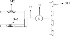
Fig. 3 is the structural representation of absorption liquid tapping equipment among the utility model embodiment.
Fig. 4 is the structural representation of absorption liquid EGR among the utility model embodiment.
Fig. 5 is the structural representation of filter among the utility model embodiment.
Fig. 6 is the vertical view (the relative position schematic diagram that absorption liquid circulation pipe delivery port and filter are arranged among the figure) of Fig. 5.
Fig. 7 is the structure enlarged drawing of absorption liquid circulation pipe delivery port among Fig. 6.
Fig. 8 is the filter jack schematic diagram on Rose Box 21 sidewall panelings among the utility model embodiment.
Fig. 9 is the front and rear wall board slot rail and the sidewall paneling filter jack relative position figure of Rose Box 21 among the utility model embodiment.
Figure 10 is the structure enlarged drawing of filter rail groove among Fig. 9.
Figure 11 is the structure chart of the solid matter settlement plate among the utility model embodiment.
Figure 12 is the profile of the percussive cap among the utility model embodiment.
Figure 13 is the connected mode structural representation of communicating pipe and liquid level box and Rose Box among the utility model embodiment.
Figure 14 is the fluid level control device schematic diagram among the utility model embodiment.
Below in conjunction with accompanying drawing 1-14 concrete structure of the present utility model is elaborated:
The specific embodiment:
Embodiment: present embodiment is formed by air inlet pipe, gas extraction filter, absorption liquid circulation and tapping equipment, absorption liquid fluid level control device, electrical equipment control and display unit group structure.
Shown in Figure 1, the gas extraction filter comprises that the top is the Rose Box 21 of taper type, the base plate of Rose Box 21 is obliquely installed, the lowest part of base plate is connected with absorption liquid delivery pipe 33, the highest point of base plate is connected with communicating pipe 42, the internal diameter of discharging of waste liquid pipe 33 is greater than the internal diameter of communicating pipe 42, communicating pipes 42 top casing on be horizontally installed with solid matter settlement plate 22, the top of a little higher than solid matter settlement plate 22 is connected with the water inlet end of absorption liquid circulation pipe 31, blast pipe 12 stretches into Rose Box and stretches out the absorption liquid liquid level, blast pipe 12 air outlets slightly eminence percussive cap 23 with blast pipe 12 concentrics is installed, the profile of percussive cap 23 is a taper type, cross section is M shape, percussive cap 23 is fixed on the blast pipe 12 by supporting leg, be higher than in the casing of percussive cap 23 and be tiltedly installed with 4 layers of filter 24,2 layers of filter of equidirectional insertion are parallel to each other, leave gap 29 between the side plate of the low side of every layer of filter and Rose Box 21, the sectional area in gap 29 is a bit larger tham the sectional area sum of the delivery port 311 of absorption liquid circulation pipe 31, the lower end of orlop filter is provided with gas flow guiding angle 20, Rose Box 21 tops are connected with aiutage 30, dry type cartridge filter 25 is installed in the aiutage 30 successively, blower fan 11, muffler 26, between dry type cartridge filter 25 and muffler 26, be provided with blower fan 11, end is equipped with muffler 26, and Rose Box 21 top the superiors filters 24 high-end sides have the insertion mouth of absorption liquid circulation pipe 31.
Shown in Figure 2, the bottom of dry type cartridge filter 25 is provided with certain thickness wire or nonmetal wire piece 251, be used for removing the fog that gas is carried secretly behind the wet filter, the middle part is a cavity 252, can be according to the character of the waste gas different adsorbent of packing into, one deck silk screen 253 is arranged at top, is used for stopping that filler is not blown away by high velocity air.
Shown in Figure 3, the absorption liquid tapping equipment comprises absorption liquid delivery pipe 33, in absorption liquid delivery pipe 33 pipelines electrical ball valve 341 is installed, and electrical ball valve 341 bottoms promptly are connected with overflow pipe 43 on the pipeline away from Rose Box 21.
Shown in Figure 4, the absorption liquid EGR comprises absorption liquid circulation pipe 31 and water pump 32.The water inlet of absorption liquid circulation pipe 31 is divided into two-way, one the tunnel is equipped with electrical ball valve 342, water inlet links to each other with Rose Box 21, another road is equipped with electrical ball valve 343, water inlet stretches into liquid level box 41 absorption liquids and sets below the liquid level, referring to Figure 14, the delivery port of absorption liquid circulation pipe stretches into the top of crossing the higher side of the superiors' filter 24 horizontal levels in the Rose Box 21, referring to Fig. 1.
Shown in Figure 5, filter 24 comprises artificial sponge 244 and carriage thereof, one end of carriage is a baffle plate 243, when being used for filter 24 and inserting Rose Boxes 21 and the sealing of filter jack 28, baffle plate 243 is connected with entity carriage limit 242,242 one side that link to each other with sponge 244 have the sponge 244 that U type groove is used for fixing insertion, the other end of carriage is the carriage limit 245 of hollow, be used to insert artificial sponge 244, have uniform micropore 247 on 245, the bottom of carriage is a mesh grille 246, is used to support artificial sponge 244, and the top of carriage is flow guide bar 241 longitudinally.
Shown in Figure 6, absorption liquid circulation pipe delivery port 311 is corresponding one by one with the guiding gutter that flow guide bar 241 is separated to form, and the moisture film that absorption liquid is formed when filter 24 flows is more even.
Shown in Figure 7, delivery port is trapezoidal flat outlet, helps absorption liquid and form uniform moisture film on filter 24.
Shown in Figure 8, each filter jack 28 is horizontally disposed with and is parallel to each other.
Shown in Figure 9, the front and back wallboard of Rose Box 21 is provided with grooved rail 27, the side plate of Rose Box 21 is provided with filter jack 28, a higher end of grooved rail 27 is corresponding with the position of filter jack 28, each filter grooved rail 27 all tilt to be installed and equidirectional being parallel to each other, and it is high-end to link to each other with filter jack 28.
Shown in Figure 10, the filter grooved rail is for being U type groove, and filter 24 is inserted into the filter grooved rail 27 after filter jack 28 inserts, filter grooved rail 27 fixedly filter 24 the position and play a supportive role.
Shown in Figure 11, solid matter settlement plate 22 is to be connected to form by a plurality of trapezoidal funnel open-mouths, and porous plate is formed at top, and the bottom is the groove of rule, and solid matter settlement plate 22 can stop that the absorption liquid of its underpart participates in circulation.
Shown in Figure 12, profile is that percussive cap 23 that taper type, cross section are M shape stops that waste gas in the blast pipe 12 makes it change flow direction and rushes at absorption liquid, and the particle in the waste gas directly falls into absorption liquid, and all the other waste gas are scattered in the Rose Box 21.
Shown in Figure 13, communicating pipe 42 bottom with liquid level box 41 link to each other, an end higher with inclined-plane, the bottom horizontal level of Rose Box 21 links to each other.
Shown in Figure 14, fluid level control device comprises liquid level box 41, its bottom linked to each other with communicating pipe 42, the middle part is higher than design liquid level place and links to each other with overflow pipe 43, the top is equipped with floating-ball level switch 44, water inlet pipe 46, and pipeline self sucking pump 47 is installed on the water inlet pipe 46, and the top has reagent and adds hand-hole 45, one road water inlet pipe of absorption liquid circulation pipe 31 stretches into absorption liquid from liquid level box 41 tops and sets below the liquid level, and electrical ball valve 343 is installed on it.
Electrical equipment control and display unit comprise frequency converter, control and display floater, frequency converter is used for controlling the rotating speed of blower fan 11, control and display floater are used for controlling the startup of water pump 32, electrical ball valve 341,342,343 and closing, and the duty that shows blower fan 11, water pump 32, electrical ball valve 341,342,343 and pipeline self sucking pump 47.
In sum, the utility model has been integrated into wet filter and dry type filtration in the system.Waste gas enters Rose Box 21 through blast pipe 12 under the active force of blower fan 11, at first changed flow direction by percussive cap 23, wherein the graininess solid matter falls into absorption liquid and passes solid matter settlement plate 22 and falls to Rose Box 21 bottoms when air-flow contacts with the absorption liquid liquid level, all the other waste gas disperses are in Rose Box 21 and disperse to rise and to pass moisture film on filter 24 and the filter 24, after dry type cartridge filter 25 demists and filter the back and enter atmosphere by muffler 26; Water pump 32 with the absorption liquid of Rose Box 21 bottoms through absorption liquid circulation pipe 31, electrical ball valve 342, absorption liquid circulation pipe delivery port 311 is transported on the entity carriage limit 242 of the filter 24 of the superiors in the Rose Box 21, absorption liquid forms moisture film on filter 24, flow through micropore 247 on the carriage limit 245 after 29 places, slit form water seal, because of the gravity effect is passed on the entity carriage limit 242 that slit 29 flows to down one deck filter 24, when hydrops on the slit 29 more for a long time hydrops cover micropore 247 and passing under the gravity effect on the entity carriage limit 242 that micropore 247 flows to lower floor's filter 24, through a plurality of identical process, flow to Rose Box 21 bottoms at last, proportion falls to Rose Box 21 bottoms greater than the solid matter of absorption liquid by solid matter settlement plate 22 in the absorption liquid; When changing absorption liquid, open electrical ball valve 341 and 343 by control and display floater, close electrical ball valve 342, this moment, absorption liquid began discharging, absorption liquid flows into Rose Box 21 from liquid level box 41 through communicating pipe 42, water pump 32 extracts absorption liquid from liquid level box 41, when the absorption liquid discharging causes the absorption liquid liquid level to drop to setting height, floating-ball level switch 44 sends the liquid feeding signal, pipeline self sucking pump 47 starts liquid feeding, and absorption liquid is changed and finished, and closes electrical ball valve 341, when the absorption liquid liquid level is elevated to setting height, floating-ball level switch 44 sends stop signal, and pipeline self sucking pump 47 quits work, and opens electrical ball valve 342, close electrical ball valve 343, gas filter system changes normal operating conditions over to.
The utility model makes up the waste gas filtering mode of having used wet method to add dry filtration, has enlarged the absorption region of waste gas, has improved absorptivity, and can be widely used in key component is the filtration of non-organic complex component waste gas and foul atmosphere.
Claims (10)
1. gas-filtering device, it is characterized in that: it comprises blast pipe, the gas extraction filter, absorption liquid circulation and tapping equipment, the absorption liquid fluid level control device, electrical equipment control and display unit, one end of blast pipe (12) extend into the middle part in the gas filtration case (21) of gas extraction filter and protrudes upward the absorption liquid liquid level, the gas extraction filter connects absorption liquid circulation and tapping equipment, the absorption liquid fluid level control device, the gas extraction filter comprises wet filter case (21), dry type cartridge filter (25), blower fan (11), muffler (26), be provided with solid matter settlement plate (22) in the wet filter case (21), percussive cap (23), channelization angle (20), filter (24) is provided with dry type cartridge filter (25) successively in wet filter case (21) the upper gas discharge drum (30), blower fan (11), muffler (26); Absorption liquid circulation and tapping equipment comprise absorption liquid circulation pipe (31), water pump (32), absorption liquid delivery pipe (33), absorption liquid circulation pipe (31) is provided with water pump (32), liquid outlet (311), the feed tube of absorption liquid circulation pipe (31) is divided into two-way, one the tunnel is communicated with bottom Rose Box (21), another road extend into liquid level box (41) absorption liquid and sets below the liquid level, the liquid outlet (311) of absorption liquid circulation pipe (31) is complementary with the guiding gutter of filter (24), and absorption liquid delivery pipe (33) is provided with electrical ball valve (341); The absorption liquid fluid level control device comprises that liquid level box (41), communicating pipe (42), overflow pipe (43), floating-ball level switch (44), reagent add hand-hole (45), filling pipe (46), pipeline self sucking pump (47), liquid level box (41) connects wet filter case (21) by communicating pipe (42), overflow pipe (43), floating-ball level switch (44), reagent add hand-hole (45), filling pipe (46) is installed on the liquid level box (41), and filling pipe (46) is provided with pipeline self sucking pump (47); Electrical equipment control and display unit comprise frequency converter, control and display floater, Frequency Converter Control blower fan (11), control and display floater are used for controlling the startup of water pump (32), electrical ball valve and closing, and the duty that shows blower fan (11), water pump (32), electrical ball valve and pipeline self sucking pump (47).
2. according to the described a kind of gas-filtering device of claim 1, it is characterized in that: the profile of described percussive cap (23) is that taper type, axial cross section are M shape, and percussive cap (23) is coaxial with blast pipe (12).
3. according to the described a kind of gas-filtering device of claim 1, it is characterized in that: described Rose Box (21) left side plate is provided with the filter jack (28) of some horizontal parallel, and the filter grooved rail (27) that is used with filter jack (28) is installed on the boxboard of front and back.
4. according to the described a kind of gas-filtering device of claim 1, it is characterized in that: described dry type cartridge filter (25) bottom is the gas-liquid separation net (251) of wire piece or nonmetal wire piece composition, the middle part is cavity (252), silk screen (253) is arranged at top, cavity is equipped with adsorbent in (252), and the two ends of dry type cartridge filter (25) are connected with gas discharge drum (30) by flange.
5. according to the described a kind of gas-filtering device of claim 1, it is characterized in that: described filter (24) is the assembly of artificial sponge and filter carriage, one end of filter carriage is baffle plate (243), when being used for filter (24) and inserting Rose Box (21) and the sealing of filter jack (28), baffle plate (243) is connected with entity carriage limit (242), (242) one side that links to each other with sponge (244) has the sponge (244) that U type groove is used for fixing insertion, the other end of carriage is the carriage limit (245) of hollow, be used to insert artificial sponge (244), (245) have uniform micropore (247) on, the bottom of carriage is mesh grille (246), be used to support artificial sponge (244), the top of carriage is flow guide bar (241) longitudinally.
6. according to the described a kind of gas-filtering device of claim 3, it is characterized in that: several filters that described filter inserts from the left side are parallel to each other; Several filters that insert from the right side are parallel to each other; Gap (29) between the limit (242) of the limit of each filter (245) and adjacent following one deck filter equates, and the equal in length of the clearance distance between the tank wall of the limit of each filter (245) and Rose Box (21) and gap (29) can form water seal when absorption liquid flows down; The horizontal line on the limit of orlop filter (245) is higher than percussive cap (23).
7. according to the described a kind of gas-filtering device of claim 1, it is characterized in that: the lower horizontal of described Rose Box (21) is equipped with solid matter settlement plate (22), solid matter settlement plate (22) is positioned at the top of communicating pipe (42), solid matter settlement plate (22) is to be connected to form by a plurality of trapezoidal funnel open-mouths, porous plate is formed at top, the bottom is the groove of rule, solid matter settlement plate (22) can stop that the absorption liquid of its underpart participates in circulation, and solid matter can pass settlement plate (22) and fall to Rose Box (21) bottom.
8. according to the described a kind of gas-filtering device of claim 1, it is characterized in that: the feed tube of described absorption liquid circulation pipe (31) is divided into two-way, one road height and close absorption liquid delivery pipe one side from a little higher than solid matter settlement plate of the rear wall of gas filtration case (21) (22) stretches into Rose Box (21), and the mouth of pipe is positioned at absorption liquid and sets below the liquid level; Another road is stretched into liquid level box (41) absorption liquid and is set below the liquid level, and the upper end of absorption liquid circulation pipe (31) penetrates the gas filtration case from limit (242) one sides of the superiors' filter (24).
9. according to the described a kind of gas-filtering device of claim 1, it is characterized in that: the upper end of absorption liquid circulation pipe (31) is provided with water knockout drum, delivery port (311) is trapezoidal flat, the quantity of delivery port (311) is identical with filter (24) guiding gutter number, is convenient to the interior moisture film that forms of each guiding gutter that absorption liquid is diverted to filter (24).
10. according to the described a kind of gas-filtering device of claim 1, it is characterized in that: described liquid level box (41) bottom is by linking to each other with the high-end of inclined-plane, bottom of gas filtration case (21) communicating pipe (42), and overflow pipe (43) is positioned on the absorption liquid liquid level.
Priority Applications (1)
| Application Number | Priority Date | Filing Date | Title |
|---|---|---|---|
| CN2010206354971U CN202052466U (en) | 2010-11-27 | 2010-11-27 | Gas filtering device |
Applications Claiming Priority (1)
| Application Number | Priority Date | Filing Date | Title |
|---|---|---|---|
| CN2010206354971U CN202052466U (en) | 2010-11-27 | 2010-11-27 | Gas filtering device |
Publications (1)
| Publication Number | Publication Date |
|---|---|
| CN202052466U true CN202052466U (en) | 2011-11-30 |
Family
ID=45012453
Family Applications (1)
| Application Number | Title | Priority Date | Filing Date |
|---|---|---|---|
| CN2010206354971U Expired - Fee Related CN202052466U (en) | 2010-11-27 | 2010-11-27 | Gas filtering device |
Country Status (1)
| Country | Link |
|---|---|
| CN (1) | CN202052466U (en) |
Cited By (12)
| Publication number | Priority date | Publication date | Assignee | Title |
|---|---|---|---|---|
| CN102059031A (en) * | 2010-11-27 | 2011-05-18 | 赵艳萍 | Gas filter device |
| CN102973211A (en) * | 2012-11-26 | 2013-03-20 | 苏州德汇清洁科技有限公司 | Silencer and floor washing machine using same |
| CN103239966A (en) * | 2013-05-23 | 2013-08-14 | 柳州市嘉诚汽车饰件系统有限公司 | Tail gas treatment device |
| CN103961968A (en) * | 2014-05-27 | 2014-08-06 | 中国海洋石油总公司 | Filter connection cylinder used for FPSO hydrogen sulfide measuring meter |
| CN104857830A (en) * | 2015-05-20 | 2015-08-26 | 北京化工大学常州先进材料研究院 | Flue gas desulfurization device |
| CN104857850A (en) * | 2015-05-28 | 2015-08-26 | 宁波市沧海新材料开发有限公司 | Indoor polluted air treater |
| CN104874275A (en) * | 2015-05-20 | 2015-09-02 | 北京化工大学常州先进材料研究院 | Flue gas desulfurization method |
| CN105617808A (en) * | 2016-03-16 | 2016-06-01 | 三峡大学 | Silent dust removal device |
| CN107281873A (en) * | 2017-07-20 | 2017-10-24 | 朱新超 | A kind of Weaving device air cleaner |
| CN109786076A (en) * | 2019-02-01 | 2019-05-21 | 国网浙江省电力有限公司宁波供电公司 | The single hole vacuum oil equipment and correction oil injection method of oil-immersed transformer |
| CN110585874A (en) * | 2019-10-14 | 2019-12-20 | 苏州仕净环保科技股份有限公司 | Sintering flue gas desulfurization and denitrification device |
| CN111878921A (en) * | 2020-07-28 | 2020-11-03 | 陈勇 | Water-saving wet-type air purification equipment |
-
2010
- 2010-11-27 CN CN2010206354971U patent/CN202052466U/en not_active Expired - Fee Related
Cited By (18)
| Publication number | Priority date | Publication date | Assignee | Title |
|---|---|---|---|---|
| CN102059031B (en) * | 2010-11-27 | 2013-06-12 | 赵艳萍 | Gas filter device |
| CN102059031A (en) * | 2010-11-27 | 2011-05-18 | 赵艳萍 | Gas filter device |
| CN102973211A (en) * | 2012-11-26 | 2013-03-20 | 苏州德汇清洁科技有限公司 | Silencer and floor washing machine using same |
| CN103239966B (en) * | 2013-05-23 | 2015-09-16 | 柳州市嘉诚汽车饰件系统有限公司 | Exhaust gas processing device |
| CN103239966A (en) * | 2013-05-23 | 2013-08-14 | 柳州市嘉诚汽车饰件系统有限公司 | Tail gas treatment device |
| CN103961968A (en) * | 2014-05-27 | 2014-08-06 | 中国海洋石油总公司 | Filter connection cylinder used for FPSO hydrogen sulfide measuring meter |
| CN103961968B (en) * | 2014-05-27 | 2016-06-08 | 中国海洋石油总公司 | A kind of filtration for FPSO hydrogen sulfide measuring instrument connects cylinder |
| CN104874275A (en) * | 2015-05-20 | 2015-09-02 | 北京化工大学常州先进材料研究院 | Flue gas desulfurization method |
| CN104857830A (en) * | 2015-05-20 | 2015-08-26 | 北京化工大学常州先进材料研究院 | Flue gas desulfurization device |
| CN104857850A (en) * | 2015-05-28 | 2015-08-26 | 宁波市沧海新材料开发有限公司 | Indoor polluted air treater |
| CN105617808A (en) * | 2016-03-16 | 2016-06-01 | 三峡大学 | Silent dust removal device |
| CN107281873A (en) * | 2017-07-20 | 2017-10-24 | 朱新超 | A kind of Weaving device air cleaner |
| CN109786076A (en) * | 2019-02-01 | 2019-05-21 | 国网浙江省电力有限公司宁波供电公司 | The single hole vacuum oil equipment and correction oil injection method of oil-immersed transformer |
| CN109786076B (en) * | 2019-02-01 | 2023-12-29 | 国网浙江省电力有限公司宁波供电公司 | Single-hole vacuum oiling equipment and method for oil immersed transformer |
| CN110585874A (en) * | 2019-10-14 | 2019-12-20 | 苏州仕净环保科技股份有限公司 | Sintering flue gas desulfurization and denitrification device |
| CN110585874B (en) * | 2019-10-14 | 2024-02-13 | 苏州仕净科技股份有限公司 | Sintering flue gas desulfurization and denitrification device |
| CN111878921A (en) * | 2020-07-28 | 2020-11-03 | 陈勇 | Water-saving wet-type air purification equipment |
| CN111878921B (en) * | 2020-07-28 | 2021-12-24 | 郭米娟 | Water-saving wet-type air purification equipment |
Similar Documents
| Publication | Publication Date | Title |
|---|---|---|
| CN102059031B (en) | Gas filter device | |
| CN202052466U (en) | Gas filtering device | |
| CN101219331B (en) | Desulfurization dust separation system for coal-fired boiler flue gas | |
| JP2009240908A (en) | Wet two step flue gas desulfurization apparatus and operation method of wet two step flue gas desulfurization apparatus | |
| CN105698322A (en) | Multi-pipe jet flow type indoor air washer | |
| CN101342455B (en) | Rotational flow and spray combined desulfurizing device | |
| CN101342454B (en) | Rotational flow and spray combined desulfurizing device | |
| CN201320436Y (en) | Bag-type dust remover | |
| CN106237825A (en) | Flow-disturbing catcher and a kind of wet process of FGD dedusting absorption tower | |
| CN201208539Y (en) | Coking waste-gas combination purification apparatus | |
| CN204182256U (en) | A kind of washing degree of depth dust arrester | |
| CN101468274A (en) | Wet dust separator | |
| CN106975338A (en) | A kind of intelligent spray formula desulfurization and dust-removal method and its device | |
| CN105709540A (en) | High-efficiency spray-type water film desulphurization deduster | |
| CN104258668B (en) | A kind of washing degree of depth dust arrester | |
| CN103816792A (en) | Corrugated packing type graded water film dust remover with smoke abatement and desulfurization functions | |
| CN110465176B (en) | Flue gas dust removal desulfurization tower and flue gas desulfurization and wastewater treatment method | |
| CN201586463U (en) | Combined type boiler dust-removal and desulfurization device | |
| CN201263964Y (en) | Rotational flow and spray combined desulfurizing device | |
| CN201300034Y (en) | Vortex-sprinkling combined desulphurizing device | |
| CN107433117A (en) | Liquid gas mixing desulfurizing dust-collector | |
| CN206492392U (en) | A kind of desulfurization and ultra-clean dust collecting process system | |
| CN202263505U (en) | Wet type gas purifying device | |
| CN201399318Y (en) | Integrated dust-removal desulfurizing device | |
| CN110559837A (en) | Flue gas desulfurization tower and flue gas desulfurization and wastewater treatment process |
Legal Events
| Date | Code | Title | Description |
|---|---|---|---|
| C14 | Grant of patent or utility model | ||
| GR01 | Patent grant | ||
| C17 | Cessation of patent right | ||
| CF01 | Termination of patent right due to non-payment of annual fee |
Granted publication date: 20111130 Termination date: 20131127 |