CN202045837U - Mold core positioning structure in mold - Google Patents
Mold core positioning structure in mold Download PDFInfo
- Publication number
- CN202045837U CN202045837U CN2011201379125U CN201120137912U CN202045837U CN 202045837 U CN202045837 U CN 202045837U CN 2011201379125 U CN2011201379125 U CN 2011201379125U CN 201120137912 U CN201120137912 U CN 201120137912U CN 202045837 U CN202045837 U CN 202045837U
- Authority
- CN
- China
- Prior art keywords
- mold
- core
- positioning structure
- mold core
- plate
- Prior art date
- Legal status (The legal status is an assumption and is not a legal conclusion. Google has not performed a legal analysis and makes no representation as to the accuracy of the status listed.)
- Expired - Fee Related
Links
- 238000004519 manufacturing process Methods 0.000 abstract description 7
- 238000002347 injection Methods 0.000 abstract description 3
- 239000007924 injection Substances 0.000 abstract description 3
- 239000000463 material Substances 0.000 description 3
- 238000004513 sizing Methods 0.000 description 3
- 230000000694 effects Effects 0.000 description 2
- 238000005516 engineering process Methods 0.000 description 2
- 238000001746 injection moulding Methods 0.000 description 2
- 238000009434 installation Methods 0.000 description 2
- 238000000034 method Methods 0.000 description 2
- 230000009286 beneficial effect Effects 0.000 description 1
- 230000007812 deficiency Effects 0.000 description 1
- 230000001788 irregular Effects 0.000 description 1
- 238000000465 moulding Methods 0.000 description 1
Images

Landscapes
- Moulds For Moulding Plastics Or The Like (AREA)
Abstract
The patent discloses a mold core positioning structure in a mold and relates to the technical field of automobile molds. The mold core positioning structure aims at solving the problems of the existing mold core fixing device of the mold that the production cost is increased and the assembling operation and disassembling operation are inconvenient. The mold core positioning structure comprises a first mold plate and a second mold plate, which are laminated, as well as the mold core arranged between the first mold plate and the second mold plate, wherein the first mold plate, the second mold plate and the mold core constitute a mold cavity, a tapered bevel is arranged at one end part of the mold cavity between the first mold plate and the second mold plate, and the edge of one end surface of the mold core is contacted with the bevel. The mold core positioning structure is particularly applicable to producing hollow injection molded products.
Description
Technical field
The utility model relates to the automobile die technical field, relates in particular to the core location structure in a kind of mould.
Background technology
Injecting molding die in the rubber mold is that the sizing material that will preheat into mecystasis injects the mould first cure through the running gate system of injection mould.Be applicable to and make large-scale, heavy wall, thin-walled, complex-shaped rubber.
During hollow injection moulding parts in producing automobile, in mould, core should be set, inject the plasticity sizing material behind upper die and lower die and the core matched moulds.For guaranteeing the intensity of core, core must be lacked and be thick as much as possible.In actual production, the core quality of fit is bad, and perhaps core and die cavity installation site skew and produce overlap or the irregular phenomenon of product wall thickness occurs repeatedly has influenced the quality of rubber product.And the mold cores fixture of design specialized has not only increased production cost, and installation and disassembling section also comparatively bother.
Summary of the invention
Increase the deficiency of production cost and charge and discharge operations inconvenience at existing mold cores fixture.The purpose of this utility model provides the core location structure in a kind of mould, and it utilizes existing mold and simple in structure.
The technical scheme that its technical problem that solves the utility model adopts is: comprise the two first stacked templates, second templates and be arranged at core between described first template and second template, described first template, second template and described core constitute die cavity, an end of the die cavity between described first template and second template is provided with the groove of convergent, and the edge of an end face of described core contacts with described groove.
Further, it is tubaeform that described groove is convergent, and the edge of the end face of described core and described groove fit tightly.
The beneficial effect of this patent is: the utility model utilizes the existing structure of mould itself, and it is tubaeform that convergent is processed in the end of die cavity, makes the end edge of the core between patrix and the counterdie to fit tightly on groove.Flaring groove has played the effect of supporting to the other end of core, and the intensity gradient curve of groove also has good adaptability to the core of different length.Saved the trouble that is equipped with special-purpose core fixture, the utility model is simple in structure, and is easy to process, and can effectively reduce production costs.
Description of drawings
The invention will be further described below in conjunction with drawings and Examples;
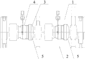
Fig. 1 is the structural representation of the counterdie of embodiment one;
Fig. 2 is the structural representation behind the mould matched moulds of embodiment one;
The number in the figure explanation:
1-patrix 2-counterdie 3-core
4-die cavity 5-groove
The specific embodiment
Below will describe technology contents of the present utility model and feature in detail by cited embodiment in conjunction with the accompanying drawings.
Embodiment one: in conjunction with Fig. 1 and Fig. 2 core location structure in a kind of mould of the present utility model is described, and when producing the hollow injection moulding parts in the automobile, injection plasticity sizing material behind patrix 1, counterdie 2 and core 3 matched moulds.Mould comprises patrix 1, the counterdie 2 that is superimposed and is arranged at two cores 3 between the template that patrix 1, counterdie 2 and core 3 constitute die cavity.An end of the die cavity 4 between patrix 1 and the counterdie 2 is provided with to die cavity 4 bottoms and is the flaring groove 5 of convergent, one end of core 3 is fixed between patrix 1 and the counterdie 2, and the edge of the other end end face of the close groove 5 of core 3 and groove 5 contacted cross sections fit tightly.
The other end of 5 pairs of cores 3 of flaring groove has played the effect of supporting, and the intensity gradient curve of groove 5 also has good adaptability to the core 3 of different length.On the basis of existing mold, the groove 5 of increase is easy to process, has solved the support problem of core 3 ends in the mould, has removed the trouble of design specialized core fixture from, has saved production cost, has improved production efficiency.
Those skilled in the art will recognize that; the above-mentioned specific embodiment is exemplary; be in order to make those skilled in the art can better understand this patent content; should not be construed as is restriction to this patent protection domain; change or modify so long as disclose spiritual any being equal to of being done, all fall into this patent protection domain according to this patent.
Claims (2)
1. the core location structure in the mould, comprise the two first stacked templates, second templates and be arranged at core between described first template and second template, described first template, second template and described core constitute die cavity, it is characterized in that: an end of the die cavity between described first template and second template is provided with the groove of convergent, and the edge of an end face of described core contacts with described groove.
2. core location structure according to claim 1 is characterized in that: it is tubaeform that described groove is convergent, and the edge of the end face of described core and described groove fit tightly.
Priority Applications (1)
| Application Number | Priority Date | Filing Date | Title |
|---|---|---|---|
| CN2011201379125U CN202045837U (en) | 2011-05-04 | 2011-05-04 | Mold core positioning structure in mold |
Applications Claiming Priority (1)
| Application Number | Priority Date | Filing Date | Title |
|---|---|---|---|
| CN2011201379125U CN202045837U (en) | 2011-05-04 | 2011-05-04 | Mold core positioning structure in mold |
Publications (1)
| Publication Number | Publication Date |
|---|---|
| CN202045837U true CN202045837U (en) | 2011-11-23 |
Family
ID=44986160
Family Applications (1)
| Application Number | Title | Priority Date | Filing Date |
|---|---|---|---|
| CN2011201379125U Expired - Fee Related CN202045837U (en) | 2011-05-04 | 2011-05-04 | Mold core positioning structure in mold |
Country Status (1)
| Country | Link |
|---|---|
| CN (1) | CN202045837U (en) |
-
2011
- 2011-05-04 CN CN2011201379125U patent/CN202045837U/en not_active Expired - Fee Related
Similar Documents
| Publication | Publication Date | Title |
|---|---|---|
| CN201419451Y (en) | Die core pulling mechanism | |
| CN102962966A (en) | An automatic cut-off gate structure of a plastic mold | |
| CN203330349U (en) | Hub forming mould | |
| CN204367321U (en) | Relay dust-proof cover die | |
| CN203472071U (en) | Runner mechanism | |
| CN202029326U (en) | Rubber flat plate transfer mould | |
| CN202388722U (en) | Injection mold capable of automatically removing nozzle | |
| CN102275270A (en) | Mold core positioning structure in mould | |
| CN203254612U (en) | Runner structure of plastic die | |
| CN204914419U (en) | Three high -efficient matrix moulds | |
| CN206383426U (en) | Automatic lid injection mold in a kind of novel multi-cavity mould | |
| CN202781680U (en) | Material feeding flow channel of injection molding mold | |
| CN204749138U (en) | Adopt injection mold who inverts gluey mode | |
| CN207224474U (en) | Improved auto parts machinery injection mold | |
| CN202572840U (en) | Injection molding die for front supporting pad of engine | |
| CN202507471U (en) | Novel mould for manufacturing rubber product | |
| CN202922896U (en) | Injection mould structure provided with nozzle capable of extending into mould | |
| CN205167408U (en) | Spring type two-way sequential ejection injection mold | |
| CN202293208U (en) | Flow channel switch for injection mold | |
| CN203994520U (en) | The injection mould of dust catcher mounting blocks | |
| CN203739126U (en) | Mould with top block pull-out water gap | |
| CN202826267U (en) | Injection mold structure of backlight source light guide plate | |
| CN202572817U (en) | Fixed mould structure of mould for manufacturing lenses by hot runner | |
| CN203019615U (en) | A mold nozzle and nozzle material release structure | |
| CN202623162U (en) | Mold for aerospace low-frequency connector |
Legal Events
| Date | Code | Title | Description |
|---|---|---|---|
| C14 | Grant of patent or utility model | ||
| GR01 | Patent grant | ||
| C17 | Cessation of patent right | ||
| CF01 | Termination of patent right due to non-payment of annual fee |
Granted publication date: 20111123 Termination date: 20120504 |