CN202026250U - Main circuit structure of inverter power module - Google Patents
Main circuit structure of inverter power module Download PDFInfo
- Publication number
- CN202026250U CN202026250U CN2011201071561U CN201120107156U CN202026250U CN 202026250 U CN202026250 U CN 202026250U CN 2011201071561 U CN2011201071561 U CN 2011201071561U CN 201120107156 U CN201120107156 U CN 201120107156U CN 202026250 U CN202026250 U CN 202026250U
- Authority
- CN
- China
- Prior art keywords
- power module
- radiator
- main circuit
- circuit structure
- inverter power
- Prior art date
- Legal status (The legal status is an assumption and is not a legal conclusion. Google has not performed a legal analysis and makes no representation as to the accuracy of the status listed.)
- Expired - Lifetime
Links
Images
Landscapes
- Inverter Devices (AREA)
Abstract
本实用新型涉及了一种逆变器功率模块主电路结构,它包括:包括压合母线(1)、直流电容阵列(2)、IGBT功率模块(3)、散热器(4)、托盘(8),直流电容阵列(2)和散热器(4)固定安装在托盘上,压合母线(1)位于直流电容阵列(2)的上方,直流电容阵列(2)的正、负极分别通过螺栓与压合母线(1)的正、负极电气相连,IGBT功率模块(3)位于散热器(4)的上方,通过螺钉与散热器(4)相连。本实用新型的逆变器功率模块主电路结构与现有的功率模块主电路结构相比,结构紧凑,布局明了,接线方便,实现模块化,便于装配、维修。

The utility model relates to a main circuit structure of an inverter power module, which comprises: a press-fit busbar (1), a DC capacitor array (2), an IGBT power module (3), a radiator (4), and a tray (8 ), the DC capacitor array (2) and the radiator (4) are fixedly installed on the tray, the press-fit busbar (1) is located above the DC capacitor array (2), and the positive and negative poles of the DC capacitor array (2) are respectively connected to the The positive and negative poles of the press-fit bus bar (1) are electrically connected, and the IGBT power module (3) is located above the radiator (4), and is connected to the radiator (4) by screws. Compared with the existing power module main circuit structure, the main circuit structure of the inverter power module of the utility model has compact structure, clear layout, convenient wiring, modularization, and convenient assembly and maintenance.
Description
技术领域 technical field
本实用新型涉及一种主电路结构,具体是一种逆变器功率模块主电路结构。 The utility model relates to a main circuit structure, in particular to a main circuit structure of an inverter power module.
背景技术 Background technique
光伏并网发电技术是可再生能源技术发展的重要组成部分,近几年也获得了长足发展,大部分技术实现了商业化,但还存在一些不足。特别是在大功率逆变器装置应用中,主电路部分布局不紧凑、接线复杂,在维护和装配方面不具有良好的操作性,尤其是在更换元器件的情况下,拆卸相当麻烦,而且早期的逆变器主电路部分散热风道不明确,或者与外围的暖通系统不兼容。 Photovoltaic grid-connected power generation technology is an important part of the development of renewable energy technology. It has also achieved considerable development in recent years. Most of the technologies have been commercialized, but there are still some shortcomings. Especially in the application of high-power inverter devices, the layout of the main circuit part is not compact, the wiring is complicated, and it does not have good operability in maintenance and assembly. Especially in the case of replacing components, disassembly is quite troublesome, and early The heat dissipation air duct of the main circuit of the inverter is not clear, or it is not compatible with the peripheral HVAC system.
发明内容 Contents of the invention
本实用新型的目的在于解决现有逆变器主电路部分结构不紧凑、接线复杂、不便于维护、装配的缺陷,而提供一种结构紧凑,布局明了,接线方便,实现模块化,便于装配、维修的逆变器功率模块主电路结构。 The purpose of this utility model is to solve the shortcomings of the existing inverter main circuit, such as uncompact structure, complicated wiring, inconvenient maintenance and assembly, and provide a compact structure, clear layout, convenient wiring, modularization, and easy assembly. Repaired inverter power module main circuit structure.
本实用新型是通过以下技术方案实现的: The utility model is achieved through the following technical solutions:
一种逆变器功率模块主电路结构,包括压合母线、直流电容阵列、IGBT功率模块、散热器、托盘,直流电容阵列和散热器固定安装在托盘上,压合母线位于直流电容阵列的上方,直流电容阵列的正、负极分别通过螺栓与压合母线的正、负极电气相连,所述IGBT功率模块位于散热器的上方,通过螺钉与散热器相连。 A main circuit structure of an inverter power module, including a press-fit busbar, a DC capacitor array, an IGBT power module, a radiator, and a tray, the DC capacitor array and the radiator are fixedly installed on the tray, and the press-fit busbar is located above the DC capacitor array , the positive and negative poles of the DC capacitor array are electrically connected to the positive and negative poles of the press-fit bus bar through bolts, and the IGBT power module is located above the radiator and connected to the radiator through screws.
一种逆变器功率模块主电路结构,其中,直流电容阵列通过电容自带螺栓固定安装在托盘上,位于散热器左侧。 A main circuit structure of an inverter power module, wherein a DC capacitor array is fixed and installed on a tray through bolts attached to the capacitor, and is located on the left side of the radiator.
一种逆变器功率模块主电路结构,还包括L型散热器安装支架,所述L型散热器安装支架的两条侧边上开设有螺孔,分别通过螺栓与散热器和托盘固定相连。 A main circuit structure of an inverter power module, further comprising an L-shaped radiator mounting bracket, screw holes are provided on two sides of the L-shaped radiator mounting bracket, and are respectively fixedly connected to the radiator and the tray by bolts.
一种逆变器功率模块主电路结构,还包括交流输出铜排,与IGBT功率模块的交流侧相连。 A main circuit structure of an inverter power module, which also includes an AC output copper bar connected to the AC side of the IGBT power module.
一种逆变器功率模块主电路结构,还包括风机,所述风机安装在托盘上,位于散热器的正下方,出风口正对着散热器的翅片。 A main circuit structure of an inverter power module, further comprising a fan, the fan is installed on the tray, located directly under the radiator, and the air outlet faces the fins of the radiator.
一种逆变器功率模块主电路结构,还包括吸收电容板,通过螺钉固定在散热器上,并与压合母线正、负极电气连接。 The main circuit structure of an inverter power module also includes a absorbing capacitor plate, which is fixed on a radiator by screws and is electrically connected to the positive and negative poles of a press-fitted bus bar.
一种逆变器功率模块主电路结构,还包括主电路模块支架,所述主电路模块支架与托盘通过螺栓垂直连接。 A main circuit structure of an inverter power module further includes a main circuit module support, and the main circuit module support is vertically connected to the tray through bolts.
本实用新型的逆变器功率模块主电路结构与现有技术相比,具有以下优点: Compared with the prior art, the main circuit structure of the inverter power module of the utility model has the following advantages:
1.直流电容阵列、散热器均固定在托盘上,形成模块化设计,可以单独做为一相输出,也可以和其他模块相互并联输出,拆卸方便,还可以分离整机进行预装配;在产品系列化的程度上可以使用通用资源,这样零件相互替代性高,维修方便。 1. The DC capacitor array and radiator are fixed on the tray to form a modular design, which can be used as a single-phase output alone, or can be output in parallel with other modules. It is easy to disassemble, and the whole machine can also be separated for pre-assembly; To the extent of product serialization, common resources can be used, so that the parts are highly interchangeable and easy to maintain.
2.更换IGBT功率模块时只需拆下散热器,不必再将主电路模块从整机中拆出后再更换IGBT。 2. When replacing the IGBT power module, it is only necessary to remove the radiator, and it is not necessary to remove the main circuit module from the whole machine to replace the IGBT.
3.结构紧凑,自下而上的风道便于散热,便于室内暖通风道配合。换热效率高,大大提高了主电路的使用寿命。 3. The structure is compact, and the bottom-up air duct is convenient for heat dissipation, which is convenient for the indoor heating air duct to cooperate. High heat exchange efficiency greatly improves the service life of the main circuit.
附图说明 Description of drawings
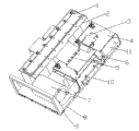
图1为本实用新型的一种逆变器功率模块主电路结构的示意图。L型散热器支架 FIG. 1 is a schematic diagram of a main circuit structure of an inverter power module of the present invention. L shape radiator bracket
在图1中,标号1为压合母线;标号2为直流电容阵列;标号3为IGBT功率模块;标号4为散热器; 标号5为吸收电容板;标号6为交流输出铜排;标号7为风机;标号8为托盘;标号9为主电路模块支架;标号10为换向铜排;标号11为L型散热器安装支架。
In Figure 1, the number 1 is the press-fit busbar; the number 2 is the DC capacitor array; the
具体实施方式 Detailed ways
一种逆变器功率模块主电路结构,包括压合母线1、直流电容阵列2、IGBT功率模块3、散热器4、吸收电容板5、交流输出铜排6、风机7、托盘8、主电路模块支架9、换向铜排10、L型散热器安装支架11。直流电容阵列2和散热器4固定安装在托盘8上,直流电容阵列2位于散热器4左侧。直流电容阵列2由多个电解电容采用先并联、后串联的方式组成,直流电容阵列2的正、负极分别通过螺栓与压合母线1的正、负极电气相连,并通过电容自带螺栓固定安装在托盘8上。压合母线1位于直流电容阵列2的上方。散热器4通过两块对称的L型散热器安装支架11固定安装在托盘8上,L型散热器安装支架11的侧边和散热器4侧边的对应位置开设有螺孔,通过螺栓将散热器与L型散热器安装支架11相连,L型散热器安装支架11的底边开设有螺孔,通过螺栓将L型散热器安装支架11固定安装在托盘8上。IGBT功率模块3位于散热器4的上方,通过螺钉与散热器4相连。吸收电容板5通过螺钉与散热器4相连,并与压合母线1的正、负极电气连接。换向铜排10与交流输出铜排6垂直连接,并通过绝缘子固定在L型散热器安装支架11上。绝缘子一端设有螺纹,固定在L型散热器安装支架11侧边的螺纹孔里,绝缘子另一端开设有有螺纹孔,通过螺栓与换向铜排10相连。风机7设置在散热器4的下方,出风口对准散热器4的翅片,形成自下而上的散热风道。为了便于主电路功率模块在机柜内竖直排放,设有主电路模块支架9,通过螺钉与托盘8垂直连接。
A main circuit structure of an inverter power module, including a press-fit bus bar 1, a DC capacitor array 2, an
以上描述是对本实用新型的解释,不是对实用新型的限定,本实用新型所限定的范围参见权利要求,在不违背本实用新型的精神的情况下,本实用新型可以作任何形式的修改。 The above description is an explanation of the utility model, not a limitation of the utility model. For the limited scope of the utility model, please refer to the claims. The utility model can be modified in any form without violating the spirit of the utility model.
Claims (7)
Priority Applications (1)
| Application Number | Priority Date | Filing Date | Title |
|---|---|---|---|
| CN2011201071561U CN202026250U (en) | 2011-04-13 | 2011-04-13 | Main circuit structure of inverter power module |
Applications Claiming Priority (1)
| Application Number | Priority Date | Filing Date | Title |
|---|---|---|---|
| CN2011201071561U CN202026250U (en) | 2011-04-13 | 2011-04-13 | Main circuit structure of inverter power module |
Publications (1)
| Publication Number | Publication Date |
|---|---|
| CN202026250U true CN202026250U (en) | 2011-11-02 |
Family
ID=44851184
Family Applications (1)
| Application Number | Title | Priority Date | Filing Date |
|---|---|---|---|
| CN2011201071561U Expired - Lifetime CN202026250U (en) | 2011-04-13 | 2011-04-13 | Main circuit structure of inverter power module |
Country Status (1)
| Country | Link |
|---|---|
| CN (1) | CN202026250U (en) |
Cited By (2)
| Publication number | Priority date | Publication date | Assignee | Title |
|---|---|---|---|---|
| CN103904912A (en) * | 2012-12-14 | 2014-07-02 | 通用汽车环球科技运作有限责任公司 | Scalable and modular approach for power electronic building block design in automotive applications |
| CN104410249A (en) * | 2014-12-12 | 2015-03-11 | 天津电气科学研究院有限公司 | Part arrangement structure for modularized power units |
-
2011
- 2011-04-13 CN CN2011201071561U patent/CN202026250U/en not_active Expired - Lifetime
Cited By (4)
| Publication number | Priority date | Publication date | Assignee | Title |
|---|---|---|---|---|
| CN103904912A (en) * | 2012-12-14 | 2014-07-02 | 通用汽车环球科技运作有限责任公司 | Scalable and modular approach for power electronic building block design in automotive applications |
| US9295184B2 (en) | 2012-12-14 | 2016-03-22 | GM Global Technology Operations LLC | Scalable and modular approach for power electronic building block design in automotive applications |
| CN103904912B (en) * | 2012-12-14 | 2016-08-17 | 通用汽车环球科技运作有限责任公司 | Expansible and the modular method of power electronics building block design in road vehicle application |
| CN104410249A (en) * | 2014-12-12 | 2015-03-11 | 天津电气科学研究院有限公司 | Part arrangement structure for modularized power units |
Similar Documents
| Publication | Publication Date | Title |
|---|---|---|
| CN103401434B (en) | A kind of power unit of large-power current transformer | |
| CN202034891U (en) | Full-water-cooling power module | |
| CN205081667U (en) | IGBT power modular structure that connects in parallel | |
| CN203883667U (en) | Thyristor self-cooling power module | |
| CN102957326A (en) | Modularized structure for three-level inverter for wind power generation | |
| CN201975982U (en) | IGBT (Insulated Gate Bipolar Translator) module of high-power converter | |
| CN110138238A (en) | A kind of power module | |
| CN203339972U (en) | Sliding-rail type IGBT water-cooling power module | |
| CN202663281U (en) | Large-power current transformer power module structure | |
| CN202713173U (en) | Inverter power module | |
| CN202798482U (en) | Power module and photovoltaic grid-connected inversion system | |
| CN102075067B (en) | Module power unit of wind power converter | |
| CN201682403U (en) | Modularized structure device of inverter unit in photovoltaic inverter | |
| CN202405648U (en) | Air-cooled radiating system of photovoltaic power generation inverter cabinet | |
| CN204517672U (en) | A kind of power layout structure of independent capacitance module | |
| CN202652082U (en) | A high-power solar three-phase grid-connected inverter | |
| CN104410249A (en) | Part arrangement structure for modularized power units | |
| CN204349814U (en) | A kind of photovoltaic DC-to-AC converter of integrated DC distribution | |
| CN201846093U (en) | Photovoltaic inverter power unit | |
| CN203243232U (en) | Inverter and power module main circuit structure thereof | |
| CN202949366U (en) | Modular structure of three-level converter for wind power generation | |
| CN202713172U (en) | Power module of wind power converter | |
| CN203313041U (en) | Flexible direct-current power transmission power module | |
| CN203691254U (en) | Power unit structure for 100kw photovoltaic inverter | |
| CN204408172U (en) | A kind of component arrangement structure of modular power unit |
Legal Events
| Date | Code | Title | Description |
|---|---|---|---|
| C14 | Grant of patent or utility model | ||
| GR01 | Patent grant | ||
| CX01 | Expiry of patent term |
Granted publication date: 20111102 |
|
| CX01 | Expiry of patent term |