CN202024293U - Heat sink device - Google Patents
Heat sink device Download PDFInfo
- Publication number
- CN202024293U CN202024293U CN2011200615309U CN201120061530U CN202024293U CN 202024293 U CN202024293 U CN 202024293U CN 2011200615309 U CN2011200615309 U CN 2011200615309U CN 201120061530 U CN201120061530 U CN 201120061530U CN 202024293 U CN202024293 U CN 202024293U
- Authority
- CN
- China
- Prior art keywords
- fin
- channel
- heat
- heat abstractor
- wall
- Prior art date
- Legal status (The legal status is an assumption and is not a legal conclusion. Google has not performed a legal analysis and makes no representation as to the accuracy of the status listed.)
- Expired - Fee Related
Links
- 230000017525 heat dissipation Effects 0.000 claims abstract description 17
- 230000007423 decrease Effects 0.000 abstract 1
- 230000000694 effects Effects 0.000 description 20
- 238000005034 decoration Methods 0.000 description 6
- 230000005855 radiation Effects 0.000 description 5
- 238000001149 thermolysis Methods 0.000 description 3
- 238000009423 ventilation Methods 0.000 description 3
- 239000000463 material Substances 0.000 description 2
- 230000000630 rising effect Effects 0.000 description 2
- 235000009967 Erodium cicutarium Nutrition 0.000 description 1
- 238000009825 accumulation Methods 0.000 description 1
- 230000009286 beneficial effect Effects 0.000 description 1
- 239000012141 concentrate Substances 0.000 description 1
- 238000010586 diagram Methods 0.000 description 1
- 230000000007 visual effect Effects 0.000 description 1
- 239000002699 waste material Substances 0.000 description 1
Images




Landscapes
- Arrangement Of Elements, Cooling, Sealing, Or The Like Of Lighting Devices (AREA)
Abstract
The utility model relates to a heat abstractor contains the fin, and adjacent fin forms the passageway, and the fin is connected in the inner wall, and this passageway volume from the bottom up is for reducing gradually. The channel volume decreases from the outside to the inside. The whole radiating fin is of an arc-shaped structure, and the top end of the radiating fin to the outer side of the radiating fin is of the arc-shaped structure. The channel is divided into a heat dissipation channel and an air convection channel, a plurality of longitudinal grooves are arranged on the outer side of the inner wall, the longitudinal grooves are connected with the heat dissipation channel, protruding grooves are formed between the longitudinal grooves and connected with the air convection channel, a plurality of compartments are arranged on the inner wall, and the compartments are communicated with the air convection channel. The inner wall of the compartment is annularly arranged. The cells are equidistantly distributed on the inner wall. The utility model provides a heat abstractor contains fin and heat dissipation channel, and the fin is connected in the inner wall, and this heat dissipation channel volume from the bottom up is for reducing gradually.
Description
Technical field
The utility model relates to the thermal component in a kind of lamp decoration field, and especially a kind of have the heat conduction of having concurrently and can utilize cross-ventilation to reduce the high-quality heat abstractor of temperature again.
Background technology
Heat abstractor is the vitals in LED lamp decoration field, and its heat conduction and heat radiation performance directly influences the service life of LED light fixture.
See also Fig. 1 to shown in Figure 3, it is followed successively by existing taper heat abstractor on the market, circular arc heat abstractor and heronsbill shape heat abstractor, and its common trait is: the heat dissipation channel B that has some fin A and formed naturally by fin A spacing.Heat abstractor relies on the effect of doing to dispel the heat that contacts between its fin and the air.In order to increase the contact area of fin and air, existing many heat abstractors are put forth effort on the area of dissipation that strengthens fin, but this mode has but been brought the another one problem: ignore the effect that utilizes cross-ventilation to accelerate to dispel the heat.That is to say, in the area of dissipation that increases fin simply, reduced the distance between each fin, and caused heat dissipation channel B gap too small, heat can't be derived fast, can't utilize natural convection air to realize quick heat radiating, heat accumulation forms the C of the portion that gathers of heat in the inside of heat abstractor itself, makes heat to discharge, radiating effect is not good, and then has influence on the service life of LED lamp decoration.
Furtherly, the technical problem that existing heat abstractor all will solve radiating effect concentrates on the area that how to increase fin, how to discharge heat and ignored.Though this kind product seems to have the large tracts of land fin, radiating effect and give between people's the visual sense and have certain difference often, and, excessive fin can cause heat abstractor excessive, waste of material, and then make cost too high, also be unfavorable for the outward appearance performance of whole lamp body.
The utility model content
The technical problem that the utility model solved is to change the technical thought of existing traditional product, provides a kind of and has the heat conduction of having concurrently and can utilize cross-ventilation to reduce the high-quality heat radiating fin structure of temperature again.
The technical solution adopted in the utility model is: a kind of heat abstractor, comprise fin, and adjacent fin forms passage, and fin is connected in inwall, and this channel volume is from top to bottom for reducing gradually.
This channel volume is from outside to inside for reducing gradually.
This fin integral body is arcuate structure, and its top is an arcuate structure to the fin outside.
This passage comprises heat dissipation channel and air convection channel, and this inner wall outside is provided with some longitudinal flutings, and this longitudinal fluting connects heat dissipation channel, form projecting slot between the longitudinal fluting, projecting slot connects air convection channel, and this inwall is provided with some compartments, and compartment is communicated with air convection channel.
This compartment is provided with ringwise in inwall.
Each compartment is equally spaced in inwall.
The utlity model has following beneficial effect: the utility model adopts said structure, heat against fin along stack effect toward rising good heat dissipation effect.The compartment of inwall also increases radiating surface simultaneously as cross-ventilated air-vent, strengthens the thermolysis of entire heat dissipation device.See through the design of above science, allow heat abstractor can utilize stack effect, utilize the convection current of air simultaneously, fast being directed in the air outside the heat nature.All accessories of the utility model collection are integrated, take into account simultaneously the effect of heat radiation again, allow the very natural up race of heat, guarantee that it can not accumulate in bottom and then the life-span of guaranteeing LED.
Description of drawings
Fig. 1 to Fig. 3 is the structural representation of existing several heat abstractors.
Fig. 4 is the stereogram of the utility model embodiment.
Fig. 5 is the side view of the utility model embodiment.
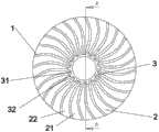
Fig. 6 is the vertical view of the utility model embodiment.
Fig. 7 is the cutaway view of A-A face among Fig. 6.
Fig. 8 is the heat volatilization schematic diagram of stack effect.
The specific embodiment
Described just as background technology, the existing heat abstractor that uses for the LED lamp decoration, because that fin and passage of heat are provided with is unreasonable, the lamp decoration heat radiation that causes is not smooth, have influence on the lamp decoration problem in service life, the utility model proposes a kind of new heat abstractor technical scheme.
See also shown in Figure 4ly, a kind of heat abstractor of the utility model comprises fin 1,1 of adjacent heat radiation forms passage 2, and fin 1 is connected in inwall, wherein, these passage 2 volumes are from top to bottom for reducing gradually, and these passage 2 volumes can also be from outside to inside for reducing gradually.Utilize this structure, make the passage of this heat abstractor can utilize the better heat conduction of stack effect, make heat discharge faster.
As shown in Figure 8, bottom Btu utilization stack effect is along with fin and passage better volatilize away.
Wherein, this fin 1 integral body is arcuate structure, its top 11 also is an arcuate structure to the fin outside 12, this kind structure makes the area of fin 1 reduce, solved the contradiction that the fin area is excessive and the heat discharge is not smooth, except saving material, the utilization rate that it has improved fin makes heat abstractor have better radiating effect.
This passage 2 is divided into heat dissipation channel 21 and air convection channel 22, these inwall 3 outsides are provided with some longitudinal flutings 31, this longitudinal fluting 31 connects heat dissipation channel 21, form projecting slot 32 between the longitudinal fluting 31, projecting slot 32 connects air convection channel 22, this inwall 3 is provided with some compartments 4, and compartment 4 is communicated with air convection channel 22.As Fig. 4 and shown in Figure 6, the heat dissipation channel and the air convection channel of this example are arranged alternately.
The above results has been accelerated the thermolysis of 1 three faces of fin, like this, utilizes the convection effects and the stack effect of air, more can effectively strengthen the radiating effect of heat abstractor.
This compartment 4 can be to be provided with ringwise in inwall, and each compartment 4 equidistantly or arbitrarily is distributed in inwall up and down.
The utility model adopts said structure, heat against fin along stack effect toward rising good heat dissipation effect.The compartment of inwall also increases radiating surface simultaneously as cross-ventilated air-vent, strengthens the thermolysis of entire heat dissipation device.See through the design of above science, allow heat abstractor can utilize stack effect, utilize the convection current of air simultaneously, fast being directed in the air outside the heat nature.All accessories of the utility model collection are integrated, take into account simultaneously the effect of heat radiation again, allow the very natural up race of heat, guarantee that it can not accumulate in bottom and then the life-span of guaranteeing LED.
Claims (6)
1. a heat abstractor comprises fin, and adjacent fin forms passage, and fin is connected in inwall, it is characterized in that, this channel volume is from top to bottom for reducing gradually.
2. heat abstractor as claimed in claim 1 is characterized in that, this channel volume is from outside to inside for reducing gradually.
3. heat abstractor as claimed in claim 1 or 2 is characterized in that, this fin integral body is arcuate structure, and its top is an arcuate structure to the fin outside.
4. heat abstractor as claimed in claim 1 or 2, it is characterized in that, this passage comprises heat dissipation channel and air convection channel, this inner wall outside is provided with some longitudinal flutings, this longitudinal fluting connects heat dissipation channel, forms projecting slot between the longitudinal fluting, and projecting slot connects air convection channel, this inwall is provided with some compartments, and compartment is communicated with air convection channel.
5. heat abstractor as claimed in claim 4 is characterized in that this compartment is provided with ringwise in inwall.
6. heat abstractor as claimed in claim 5 is characterized in that each compartment is equally spaced in inwall.
Priority Applications (1)
| Application Number | Priority Date | Filing Date | Title |
|---|---|---|---|
| CN2011200615309U CN202024293U (en) | 2011-03-10 | 2011-03-10 | Heat sink device |
Applications Claiming Priority (1)
| Application Number | Priority Date | Filing Date | Title |
|---|---|---|---|
| CN2011200615309U CN202024293U (en) | 2011-03-10 | 2011-03-10 | Heat sink device |
Publications (1)
| Publication Number | Publication Date |
|---|---|
| CN202024293U true CN202024293U (en) | 2011-11-02 |
Family
ID=44849241
Family Applications (1)
| Application Number | Title | Priority Date | Filing Date |
|---|---|---|---|
| CN2011200615309U Expired - Fee Related CN202024293U (en) | 2011-03-10 | 2011-03-10 | Heat sink device |
Country Status (1)
| Country | Link |
|---|---|
| CN (1) | CN202024293U (en) |
-
2011
- 2011-03-10 CN CN2011200615309U patent/CN202024293U/en not_active Expired - Fee Related
Similar Documents
| Publication | Publication Date | Title |
|---|---|---|
| CN203036599U (en) | Structure of radiator with built-in fins | |
| CN202505009U (en) | Novel energy-saving pot | |
| CN202505015U (en) | Energy-saving pot | |
| CN102679290A (en) | heat sink | |
| CN203980214U (en) | A kind of LED street lamp cooling mechanism | |
| CN203586626U (en) | Energy-saving air-returning pipe assembly and mould | |
| CN203857333U (en) | LED ceramic bulb lamp facilitating heat dissipation | |
| CN104075501A (en) | Tube-on-sheet evaporator | |
| CN203162900U (en) | Light-emitting diode (LED) lamp radiator | |
| CN201814370U (en) | Energy-saving pot | |
| CN203585891U (en) | Radiating LED (light emitting diode) lamp | |
| CN202992810U (en) | A kind of efficient heat dissipation LED lamp | |
| CN202361107U (en) | LED energy-saving lamp with complex heat dissipation mechanism | |
| CN203464005U (en) | Novel adsorption type LED down lamp | |
| CN203190366U (en) | Radiating tube section bar of LED lamp | |
| CN203642118U (en) | heat sink | |
| CN203339215U (en) | A LED high-power bracket | |
| CN204045337U (en) | Novel oil-guiding formula transformer | |
| CN202791615U (en) | Light emitting diode (LED) road lamp structure with heat conducting hole hot runner | |
| CN203887279U (en) | Sand-grain hole saw | |
| CN202302835U (en) | LED (Light-Emitting Diode) energy-saving lamp with porous sun flower-shaped heat radiator | |
| CN203585893U (en) | LED lamp provided with radiator | |
| CN203215633U (en) | Lamp radiator | |
| CN203564073U (en) | Energy-saving pan | |
| CN204461185U (en) | A kind of fin |
Legal Events
| Date | Code | Title | Description |
|---|---|---|---|
| C14 | Grant of patent or utility model | ||
| GR01 | Patent grant | ||
| CF01 | Termination of patent right due to non-payment of annual fee |
Granted publication date: 20111102 Termination date: 20150310 |
|
| EXPY | Termination of patent right or utility model |