CN202021713U - Inner slide block mechanism - Google Patents
Inner slide block mechanism Download PDFInfo
- Publication number
- CN202021713U CN202021713U CN2011200774964U CN201120077496U CN202021713U CN 202021713 U CN202021713 U CN 202021713U CN 2011200774964 U CN2011200774964 U CN 2011200774964U CN 201120077496 U CN201120077496 U CN 201120077496U CN 202021713 U CN202021713 U CN 202021713U
- Authority
- CN
- China
- Prior art keywords
- mould
- male
- top plate
- mentioned
- slider mechanism
- Prior art date
- Legal status (The legal status is an assumption and is not a legal conclusion. Google has not performed a legal analysis and makes no representation as to the accuracy of the status listed.)
- Expired - Lifetime
Links
Images


Landscapes
- Moulds For Moulding Plastics Or The Like (AREA)
Abstract
一种内滑块机构,其应用于模具中,该内滑块机构包括:第一顶板,其与模具的公模板及下固定板相连接;第二顶板,其与上述第一顶板相连接;限位螺钉,其一端设于模具的公模板中,另一端活动设于上述第二顶板中;导向杆,其一端设于上述第一顶板中,另一端设于模具的公模仁中,并设有若干凹槽;公模入子,其设于模具的公模仁中,并套设在上述导向杆外部,在该公模入子上还设有若干通孔;若干滑块入子,其设于模具的公模仁中,该滑块入子一侧与产品相接触,另一侧设有凸块,该凸块分别与上述凹槽相配合,并可沿凹槽方向运动。本实用新型的内滑块机构,可以完全且安全的退出产品倒勾,可开一模多穴,便于加工,提高了生产效率,降低生产成本。
An inner slider mechanism, which is applied in a mould, the inner slider mechanism includes: a first top plate, which is connected with a male template and a lower fixing plate of the mould; a second top plate, which is connected with the above-mentioned first top plate; A limit screw, one end of which is set in the male template of the mould, and the other end is movably set in the above-mentioned second top plate; a guide rod, one end of which is set in the above-mentioned first top plate, and the other end is set in the male mold core of the mould, and There are several grooves; the male mold inserts are set in the male mold core of the mold and are sleeved outside the above-mentioned guide rod, and several through holes are also provided on the male mold inserts; several slider inserts, It is set in the male core of the mould. One side of the slider is in contact with the product, and the other side is provided with bumps. The bumps are respectively matched with the above grooves and can move along the direction of the grooves. The inner slider mechanism of the utility model can completely and safely withdraw the product undercut, can open a mold with multiple cavities, facilitates processing, improves production efficiency, and reduces production costs.
Description
【技术领域】 【Technical field】
本实用新型涉及一种滑块机构,具体涉及一种内滑块机构。 The utility model relates to a slider mechanism, in particular to an inner slider mechanism. the
【背景技术】 【Background technique】
在模具生产中,有时会遇到产品周圈有倒勾且内部空间较小的情况,如图1所示,此类结构需要用滑块机构或斜销机构来成型。用现有滑块机构即外滑块机构成型时,模具只能开一模一穴,增加了生产成本;用现有斜销机构成型时,因产品10内部空间较小,斜销在退出倒勾11时会干涉,导致斜销无法退出。 In the production of molds, it is sometimes encountered that the circumference of the product has barbs and the internal space is small, as shown in Figure 1, such structures need to be formed by a slider mechanism or an oblique pin mechanism. When forming with the existing slider mechanism, that is, the outer slider mechanism, the mold can only open one mold and one cavity, which increases the production cost; When hooking 11, it will interfere, causing the oblique pin to fail to withdraw. the
有鉴于此,实有必要开发一种内滑块机构,该内滑块机构可以解决现有滑块机构和斜销机构存在的问题,采用此机构模具能开一模多穴,并能完全且安全的退出产品倒勾,可大大提高生产效率,且便于加工,降低了生产成本。 In view of this, it is really necessary to develop an inner slider mechanism, which can solve the problems existing in the existing slider mechanism and oblique pin mechanism. Using this mechanism, the mold can open a mold with multiple cavities, and can completely and Safe withdrawal of product barbs can greatly improve production efficiency, facilitate processing, and reduce production costs. the
【发明内容】 【Content of invention】
因此,本实用新型的目的是开发一种内滑块机构,该内滑块机构可以完全且安全的退出产品倒勾,并能开一模多穴,提高了生产效率,降低生产成本。 Therefore, the purpose of this utility model is to develop an inner slider mechanism, which can completely and safely exit the product undercut, and can open a mold with multiple cavities, which improves production efficiency and reduces production costs. the
本实用新型的内滑块机构,其应用于模具中,该内滑块机构包括: The inner slider mechanism of the present utility model is applied in the mold, and the inner slider mechanism includes:
第一顶板,其与模具的公模板及下固定板相连接; The first top plate, which is connected with the male template and the lower fixed plate of the mold;
第二顶板,其与上述第一顶板相连接; The second top plate, which is connected with the above-mentioned first top plate;
限位螺钉,其一端设于模具的公模板中,另一端活动设于上述第二顶板中,在上述第一顶板中设有活动空间,供该限位螺钉穿设其中; A limit screw, one end of which is set in the male template of the mold, and the other end is movably set in the above-mentioned second top plate, and a movable space is provided in the above-mentioned first top plate for the limit screw to pass through;
导向杆,其一端设于上述第一顶板中,另一端活动设于模具的公模仁中,并设有若干凹槽; A guide rod, one end of which is set in the above-mentioned first top plate, and the other end is movably set in the male core of the mould, and is provided with several grooves;
公模入子,其设于模具的公模仁中,并套设在上述导向杆外部,在该公模入子上还设有若干通孔; The male mold insert is set in the male mold core of the mould, and is sleeved on the outside of the above-mentioned guide rod, and several through holes are also provided on the male mold insert;
若干滑块入子,其设于模具的公模仁中,该滑块入子一侧通过上述通孔与产品相接触,另一侧设有凸块,该凸块分别与上述凹槽相配合,并可沿凹槽运动; A number of slider inserts, which are set in the male mold core of the mold, one side of the slider insert contacts the product through the above-mentioned through hole, and the other side is provided with a protrusion, and the protrusions are respectively matched with the above-mentioned grooves , and can move along the groove;
开闭器,其一端设于模具的公模板中,另一端设于模具的母模板中。 One end of the shutter is arranged in the male template of the mould, and the other end is arranged in the female template of the mould. the
较佳的,上述凹槽的数量为四个。 Preferably, the number of the above-mentioned grooves is four. the
较佳的,上述通孔的数量为四个。 Preferably, the number of the above-mentioned through holes is four. the
较佳的,上述滑块入子的数量为四个。 Preferably, the number of the slider inserts is four. the
较佳的,上述凹槽为T形槽或燕尾槽。 Preferably, the above-mentioned groove is a T-shaped groove or a dovetail groove. the
较佳的,上述凸块为T形凸块或燕尾形凸块。 Preferably, the above-mentioned bumps are T-shaped bumps or dovetail-shaped bumps. the
相较于现有技术,本实用新型的内滑块机构,可以完全且安全的退出产品 倒勾,可开一模多穴,提高了生产效率,降低生产成本。 Compared with the prior art, the inner slider mechanism of the present invention can completely and safely exit the product barb, and can open multiple holes in one mold, which improves production efficiency and reduces production costs. the
【附图说明】 【Description of drawings】
图1绘示产品结构示意图。 Figure 1 shows a schematic diagram of the product structure. the
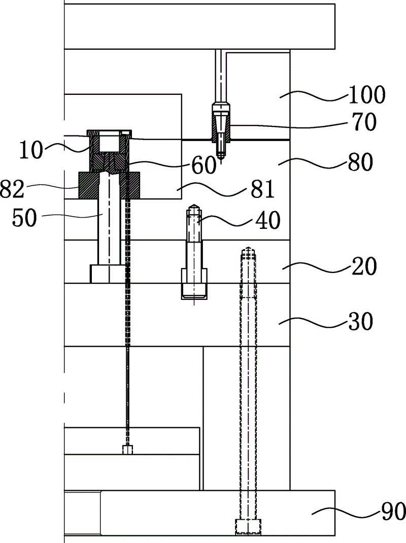
图2绘示本实用新型内滑块机构的合模状态示意图。 FIG. 2 is a schematic diagram of the mold clamping state of the inner slider mechanism of the present invention. the
图3绘示本实用新型内滑块机构的导向杆结构示意图。 FIG. 3 is a schematic diagram showing the structure of the guide rod of the inner slider mechanism of the present invention. the
图4绘示本实用新型内滑块机构的公模入子结构示意图。 FIG. 4 is a schematic diagram of the structure of the male die of the inner slider mechanism of the present invention. the
图5绘示本实用新型内滑块机构的滑块入子结构示意图。 FIG. 5 is a schematic diagram of the structure of the slider entry of the inner slider mechanism of the present invention. the
图6绘示本实用新型内滑块机构的第一开模状态示意图。 FIG. 6 is a schematic diagram of the first mold opening state of the inner slider mechanism of the present invention. the
图7绘示本实用新型内滑块机构的第二开模状态示意图。 FIG. 7 is a schematic diagram of the second mold opening state of the inner slider mechanism of the present invention. the
【具体实施方式】 【Detailed ways】
请参阅图1、图2、图3、图4、图5所示,本实用新型的内滑块机构,应用于模具中,于本实施例中,该内滑块机构包括: Please refer to Fig. 1, Fig. 2, Fig. 3, Fig. 4, and Fig. 5. The inner slider mechanism of the present invention is applied in the mold. In this embodiment, the inner slider mechanism includes:
第一顶板20,其与模具的公模板80及下固定板90相连接;
The first
第二顶板30,其与上述第一顶板20相连接;
Second
限位螺钉40,其一端设于模具的公模板80中,另一端活动设于上述第二顶板30中,在上述第一顶板20中设有活动空间,供该限位螺钉40穿设其中;
Limit
导向杆50,其一端设于上述第一顶板20中,另一端设于模具的公模仁81中,并设有四凹槽51,该四凹槽51均为T形槽或燕尾槽,在本实施例中,该四凹槽51为燕尾槽;
公模入子82,其设于模具的公模仁81中,用于成型产品10,并套设在上述导向杆50外部,在该公模入子82上还设有四个通孔821;
The
四滑块入子60,其设于模具的公模仁81中,该滑块入子60一侧通过上述通孔821与产品10相接触,以成型产品倒勾11,通孔821给滑块入子60一阻力,保证滑块入子60在模具中的定位和运动的稳定,另一侧设有凸块62,该凸块62分别与上述凹槽51相配合,并可沿凹槽51运动,该凸块62为T形凸块或燕尾形凸块,在本实施例中,该凸块62为燕尾形凸块;
Four
开闭器70,其一端设于模具的公模板80中,另一端设于模具的母模板100中。
One end of the
请参阅图6所示,当模具开模时,在机台开模力的作用下,模具的公模部分向远离母模板100的方向运动,因为公模板80和母模板100之间设有开闭器70,在开闭器70的作用下,公模板80和母模板100之间暂不开模,第一顶板20带动导向杆50与公模板80逐渐分离,滑块入子60沿导向杆50的凹槽51运动,并逐渐脱离产品倒勾11,直至限位螺钉40停止运动,此时,滑块入子60已完全脱离产品倒勾11,第一顶板20与公模板80之间完成第一次开模。
Please refer to Fig. 6, when the mold is opened, under the action of the mold opening force of the machine, the male part of the mold moves away from the
请参阅图7所示,模具继续开模,在机台开模力的作用下,公模板80与母模板100之间克服开闭器70的阻力,完成第二次开模即公模板80与母模板100 之间的开模,最后,在模具的顶针作用下,将产品10顶出模具。
Please refer to Fig. 7, the mold continues to open, under the action of the mold opening force of the machine, the resistance of the
以上所述仅为本实用新型的一较佳实施例,本实用新型的构造特征并不局限于此。此外,本实用新型的内滑块机构在其他实施例中,滑块入子及凹槽的数量可由产品的形状而定。本实用新型不在此一一赘述,任何依据本专利所作的变化均涵盖在本专利的范围内。 The above description is only a preferred embodiment of the utility model, and the structural features of the utility model are not limited thereto. In addition, in other embodiments of the inner slider mechanism of the present invention, the number of slider inserts and grooves can be determined by the shape of the product. The utility model is not described here one by one, and any changes made according to the patent are covered within the scope of the patent. the
本实用新型的内滑块机构,可以完全且安全的退出产品倒勾,可开一模多穴,便于加工,提高了生产效率,降低生产成本。 The inner slider mechanism of the utility model can completely and safely withdraw the product undercut, can open a mold with multiple cavities, facilitates processing, improves production efficiency, and reduces production costs. the
Claims (6)
Priority Applications (1)
| Application Number | Priority Date | Filing Date | Title |
|---|---|---|---|
| CN2011200774964U CN202021713U (en) | 2011-03-23 | 2011-03-23 | Inner slide block mechanism |
Applications Claiming Priority (1)
| Application Number | Priority Date | Filing Date | Title |
|---|---|---|---|
| CN2011200774964U CN202021713U (en) | 2011-03-23 | 2011-03-23 | Inner slide block mechanism |
Publications (1)
| Publication Number | Publication Date |
|---|---|
| CN202021713U true CN202021713U (en) | 2011-11-02 |
Family
ID=44846681
Family Applications (1)
| Application Number | Title | Priority Date | Filing Date |
|---|---|---|---|
| CN2011200774964U Expired - Lifetime CN202021713U (en) | 2011-03-23 | 2011-03-23 | Inner slide block mechanism |
Country Status (1)
| Country | Link |
|---|---|
| CN (1) | CN202021713U (en) |
Cited By (7)
| Publication number | Priority date | Publication date | Assignee | Title |
|---|---|---|---|---|
| CN102689381A (en) * | 2011-03-23 | 2012-09-26 | 汉达精密电子(昆山)有限公司 | Inner slider mechanism |
| CN103009517A (en) * | 2012-12-12 | 2013-04-03 | 台州市黄岩炜大塑料机械有限公司 | Plastic elbow mould pull rod inner pumping mechanism |
| CN103358496A (en) * | 2013-07-09 | 2013-10-23 | 宁波和鑫光电科技有限公司 | Core pulling device of cylindrical core with backoff structures uniformly distributed on cylindrical surface |
| CN103921411A (en) * | 2013-01-15 | 2014-07-16 | 苏州汉扬精密电子有限公司 | Two-step ejection mechanism |
| CN108956073A (en) * | 2018-07-19 | 2018-12-07 | 苏州百搭王者物流技术有限公司 | A kind of large vibration table Fast Installation structure |
| CN112318783A (en) * | 2021-01-04 | 2021-02-05 | 中国人民解放军国防科技大学 | Vacuum filling forming die for conical cylinder with smooth outer wall and sink groove |
| CN113664177A (en) * | 2020-05-15 | 2021-11-19 | 苏州汉扬精密电子有限公司 | Mould structure for controlling product position degree |
-
2011
- 2011-03-23 CN CN2011200774964U patent/CN202021713U/en not_active Expired - Lifetime
Cited By (12)
| Publication number | Priority date | Publication date | Assignee | Title |
|---|---|---|---|---|
| CN102689381A (en) * | 2011-03-23 | 2012-09-26 | 汉达精密电子(昆山)有限公司 | Inner slider mechanism |
| CN103009517A (en) * | 2012-12-12 | 2013-04-03 | 台州市黄岩炜大塑料机械有限公司 | Plastic elbow mould pull rod inner pumping mechanism |
| CN103921411A (en) * | 2013-01-15 | 2014-07-16 | 苏州汉扬精密电子有限公司 | Two-step ejection mechanism |
| CN103921411B (en) * | 2013-01-15 | 2016-12-28 | 苏州汉扬精密电子有限公司 | Secondary ejecting mechanism |
| CN103358496A (en) * | 2013-07-09 | 2013-10-23 | 宁波和鑫光电科技有限公司 | Core pulling device of cylindrical core with backoff structures uniformly distributed on cylindrical surface |
| CN103358496B (en) * | 2013-07-09 | 2016-03-02 | 宁波和鑫光电科技有限公司 | The core-pulling device of a kind of cylinder uniform back-off cylinder core |
| CN108956073A (en) * | 2018-07-19 | 2018-12-07 | 苏州百搭王者物流技术有限公司 | A kind of large vibration table Fast Installation structure |
| CN108956073B (en) * | 2018-07-19 | 2021-08-06 | 苏州百搭王者物流技术有限公司 | Quick mounting structure of large-scale shaking table |
| CN113664177A (en) * | 2020-05-15 | 2021-11-19 | 苏州汉扬精密电子有限公司 | Mould structure for controlling product position degree |
| CN113664177B (en) * | 2020-05-15 | 2024-03-19 | 苏州汉扬精密电子有限公司 | Mold structure to control product positioning |
| CN112318783A (en) * | 2021-01-04 | 2021-02-05 | 中国人民解放军国防科技大学 | Vacuum filling forming die for conical cylinder with smooth outer wall and sink groove |
| CN112318783B (en) * | 2021-01-04 | 2021-08-10 | 中国人民解放军国防科技大学 | Vacuum filling forming die for conical cylinder with smooth outer wall and sink groove |
Similar Documents
| Publication | Publication Date | Title |
|---|---|---|
| CN204249254U (en) | Substep die opening mechanism | |
| CN103934931B (en) | Slide block drawing-out mechanism | |
| CN105269769A (en) | Double-power injection mold of multi-direction oblique and curved pin core pulling structure | |
| CN102672856A (en) | Secondary core-pulling mechanism with slider for male moulds | |
| CN202021712U (en) | Secondary core pulling mechanism for sliding block of male die | |
| CN103862598A (en) | Sliding block mechanism of die | |
| CN102689381A (en) | Inner slider mechanism | |
| CN202952461U (en) | Insert locating mechanism | |
| CN203427238U (en) | mold with slider | |
| CN103963250B (en) | Double color mould two penetrates control structure for mould-matching | |
| CN106142398A (en) | The slide-exiting structure of mould | |
| CN101733880A (en) | Twice ejecting mechanism | |
| CN104108148A (en) | Demolding structure of product with female thread | |
| CN105269768A (en) | Three-plate mould female mould oblique core drawing structure | |
| CN203198111U (en) | Demolding structure with internal thread product | |
| CN103802242A (en) | Slide block withdrawal mechanism | |
| CN204136332U (en) | Casting insert interchange injection mould | |
| CN104708771B (en) | Master mold inclined sliding block structure | |
| CN202952425U (en) | Slide block exiting mechanism | |
| CN104149280B (en) | The shaping mould that is assembled into one of scissors pin | |
| CN102962915B (en) | Slide block side core-pulling mechanism | |
| CN203665857U (en) | Female die slanted slide block structure | |
| CN202062597U (en) | Slide block mechanism | |
| CN201645711U (en) | Ejector | |
| CN107042611A (en) | The external pulling type plate pushing structure of mould |
Legal Events
| Date | Code | Title | Description |
|---|---|---|---|
| C14 | Grant of patent or utility model | ||
| GR01 | Patent grant | ||
| C41 | Transfer of patent application or patent right or utility model | ||
| TR01 | Transfer of patent right |
Effective date of registration: 20160315 Address after: Suzhou City, Jiangsu province 215300 Eagle Kunshan Road Development Zone No. 66 Patentee after: Kunshan Han Ding Feinmetall GmbH Address before: 215300, No. second, 269 Avenue, Kunshan export processing zone, Suzhou, Jiangsu, China Patentee before: Mitac Precision Technology (Kunshan) Corp. |
|
| CP03 | Change of name, title or address |
Address after: 215300 No. 207, peacock Road, Kunshan Development Zone, Suzhou City, Jiangsu Province Patentee after: Kunshan Huafu Precision Metal Co., Ltd Address before: Suzhou City, Jiangsu province 215300 Eagle Kunshan Road Development Zone No. 66 Patentee before: Kunshan Han Ding Feinmetall GmbH |
|
| CP03 | Change of name, title or address | ||
| CX01 | Expiry of patent term |
Granted publication date: 20111102 |
|
| CX01 | Expiry of patent term |