CN202017931U - Combined LED Bulb - Google Patents
Combined LED Bulb Download PDFInfo
- Publication number
- CN202017931U CN202017931U CN2011200751040U CN201120075104U CN202017931U CN 202017931 U CN202017931 U CN 202017931U CN 2011200751040 U CN2011200751040 U CN 2011200751040U CN 201120075104 U CN201120075104 U CN 201120075104U CN 202017931 U CN202017931 U CN 202017931U
- Authority
- CN
- China
- Prior art keywords
- led light
- secondary optical
- light bulb
- combined led
- radiator
- Prior art date
- Legal status (The legal status is an assumption and is not a legal conclusion. Google has not performed a legal analysis and makes no representation as to the accuracy of the status listed.)
- Expired - Fee Related
Links
- 230000003287 optical effect Effects 0.000 claims abstract description 36
- 238000009792 diffusion process Methods 0.000 claims abstract description 19
- 230000000694 effects Effects 0.000 description 3
- 238000000034 method Methods 0.000 description 3
- 239000000428 dust Substances 0.000 description 2
- 230000007613 environmental effect Effects 0.000 description 2
- 238000009434 installation Methods 0.000 description 2
- XLYOFNOQVPJJNP-UHFFFAOYSA-N water Substances O XLYOFNOQVPJJNP-UHFFFAOYSA-N 0.000 description 2
- 239000000853 adhesive Substances 0.000 description 1
- 230000001070 adhesive effect Effects 0.000 description 1
- 239000000956 alloy Substances 0.000 description 1
- 229910045601 alloy Inorganic materials 0.000 description 1
- 238000001816 cooling Methods 0.000 description 1
- 238000010586 diagram Methods 0.000 description 1
- 239000003292 glue Substances 0.000 description 1
- 230000017525 heat dissipation Effects 0.000 description 1
- 239000004065 semiconductor Substances 0.000 description 1
Images

Landscapes
- Arrangement Of Elements, Cooling, Sealing, Or The Like Of Lighting Devices (AREA)
Abstract
本实用新型公开了一种组合式LED灯泡,属于LED灯技术领域,其技术要点包括绝缘灯头,其中所述的绝缘灯头内设有电源模块;绝缘灯头连接有中空的散热体,在散热体下表面设有导热片,在导热片上设有LED光源模组,在LED光源模组外围的散热体上设有二次光学扩散罩或二次光学透镜;本实用新型旨在提供一种灯泡各部可方便拆装,易于维修、更换及可以升级的组合式LED灯泡;用于室内外照明。
The utility model discloses a combined LED bulb, which belongs to the technical field of LED lamps. Its technical points include an insulating lamp holder, wherein a power module is arranged inside the insulating lamp holder; the insulating lamp holder is connected to a hollow heat sink, a heat conducting sheet is arranged on the lower surface of the heat sink, an LED light source module is arranged on the heat conducting sheet, and a secondary optical diffusion cover or a secondary optical lens is arranged on the heat sink outside the LED light source module; the utility model aims to provide a combined LED bulb whose parts can be conveniently disassembled and assembled, and which is easy to repair, replace and upgrade; and is used for indoor and outdoor lighting.
Description
技术领域technical field
本实用新型涉及一种LED灯具,更具体地说,尤其涉及一种组合式LED灯泡。The utility model relates to an LED lamp, in particular to a combined LED light bulb.
背景技术Background technique
发光二极管是利用半导体通电后的发旋光性能发光的,具有功耗低,使用寿命长的优点;目前,利用发光二极管组合的照明灯具越来越普遍,此类灯具一般是由绝缘灯座连接铝合金散热体组成,连接时采用螺丝固定连接或是粘接或是一次成型,这些连接方式存在下述缺点:(1)通过螺丝连接,使得外观不美观,拆装不方便;(2)采用粘接或是一次成型,当灯具出现问题时,就得整体一起更换,而LED灯具的故障一般是LED光源模组或是电源模块故障,其它散热器及扩散罩等都是完好的,从而造成使用成本的增加。Light-emitting diodes use the light-rotating properties of semiconductors to emit light after being energized, and have the advantages of low power consumption and long service life; at present, lighting fixtures that use light-emitting diode combinations are becoming more and more common. Composed of alloy heat sinks, the connection is fixed with screws or bonded or formed at one time. These connection methods have the following disadvantages: (1) The connection by screws makes the appearance unattractive and inconvenient to disassemble; (2) The use of adhesive When there is a problem with the lamp, it has to be replaced as a whole, and the fault of the LED lamp is generally the fault of the LED light source module or the power module, and other radiators and diffusion covers are intact, resulting in the use of cost increase.
实用新型内容Utility model content
本实用新型的目的在于针对上述现有技术的不足,提供一种灯具各部可方便拆装,易于维修、更换的组合式LED灯泡。The purpose of this utility model is to provide a combined LED light bulb which can be easily disassembled and easily maintained and replaced in order to solve the above-mentioned shortcomings of the prior art.
本实用新型的技术方案是这样实现的:一种组合式LED灯泡,包括绝缘灯头,其中所述的绝缘灯头内设有电源模块;绝缘灯头连接有中空的散热体,在散热体下表面设有导热片,在导热片上设有LED光源模组,在LED光源模组外围的散热体上设有二次光学扩散罩或二次光学透镜。The technical scheme of the utility model is realized as follows: a combined LED light bulb includes an insulating lamp cap, wherein the insulating lamp cap is provided with a power module; the insulating lamp cap is connected with a hollow radiator, and the lower surface of the radiator is provided with The heat conduction sheet is provided with an LED light source module on the heat conduction sheet, and a secondary optical diffusion cover or a secondary optical lens is provided on the radiator around the LED light source module.
上述的组合式LED灯泡中,所述的绝缘灯头与散热体的接触部之间设有上防水胶圈。In the above combined LED light bulb, an upper waterproof rubber ring is provided between the contact portion of the insulating lamp cap and the radiator.
上述的组合式LED灯泡中,所述的散热体与二次光学扩散罩或二次光学透镜之间设有下防水胶圈。In the above combined LED light bulb, a lower waterproof rubber ring is provided between the heat sink and the secondary optical diffusion cover or the secondary optical lens.
上述的组合式LED灯泡中,所述的电源模块与LED光源模组之间的连接电路上设有电源连接器,所述的电源连接器由相对应的插接头和插接座构成,插接头和插接座分别设置在电源模块和LED光源模组的连接电路端部。In the above-mentioned combined LED light bulb, a power connector is provided on the connecting circuit between the power module and the LED light source module, and the power connector is composed of a corresponding plug connector and a socket socket, and the plug connector The socket and the socket are respectively arranged at the ends of the connection circuit of the power supply module and the LED light source module.
上述的组合式LED灯泡中,所述的绝缘灯头下部外围设有上扣环,上扣环与散热体连接。In the above combined LED light bulb, an upper buckle is provided on the outer periphery of the lower part of the insulating lamp cap, and the upper buckle is connected with the radiator.
上述的组合式LED灯泡中,所述的绝缘灯头与上扣环为一体成型的整体结构。In the above-mentioned combined LED light bulb, the insulating lamp base and the upper buckle ring are integrally formed as an integral structure.
上述的组合式LED灯泡中,所述的上扣环与散热体螺纹连接。In the above combined LED light bulb, the upper buckle is screwed to the radiator.
上述的组合式LED灯泡中,所述的上扣环与散热体通过螺丝固定连接。In the above-mentioned combined LED light bulb, the upper buckle is fixedly connected to the radiator by screws.
上述的组合式LED灯泡中,所述的二次光学扩散罩或二次光学透镜上端部外围设有下扣环,下扣环与散热体螺纹连接。In the above-mentioned combined LED light bulb, a lower buckle is provided on the periphery of the upper end of the secondary optical diffusion cover or the secondary optical lens, and the lower buckle is screwed to the radiator.
上述的组合式LED灯泡中,所述的二次光学扩散罩或二次光学透镜与下扣环为一体成型的整体结构。In the aforementioned combined LED light bulb, the secondary optical diffusion cover or the secondary optical lens is integrally formed with the lower retaining ring.
本实用新型采用上述结构后,通过将电源模块设置在绝缘灯头内,同时将绝缘灯头与散热体之间、二次光学扩散罩或二次光学透镜与散热体之间以及LED光源模组与电源模块的电路连接之间设计成可拆装的活动连接,使得任何一部分出现问题时,都可以单独更换,不需要整体废弃,使得散热体及二次光学扩散罩或二次光学透镜等不易损坏的部件可以循环使用,既提高了灯具的整体使用率、大大降低了使用成本,同时也达到了环保的目的。After the utility model adopts the above-mentioned structure, by setting the power supply module in the insulating lamp cap, at the same time, between the insulating lamp cap and the radiator, between the secondary optical diffusion cover or the secondary optical lens and the radiator, and between the LED light source module and the power supply The circuit connection of the module is designed as a detachable movable connection, so that when any part has a problem, it can be replaced separately, without the need to discard the whole, so that the heat sink, secondary optical diffusion cover or secondary optical lens are not easily damaged. Parts can be recycled, which not only improves the overall utilization rate of the lamp, greatly reduces the use cost, but also achieves the purpose of environmental protection.
附图说明Description of drawings
下面结合附图中的实施例对本实用新型作进一步的详细说明,但并不构成对本实用新型的任何限制。The utility model will be further described in detail below in conjunction with the embodiments in the accompanying drawings, but it does not constitute any limitation to the utility model.
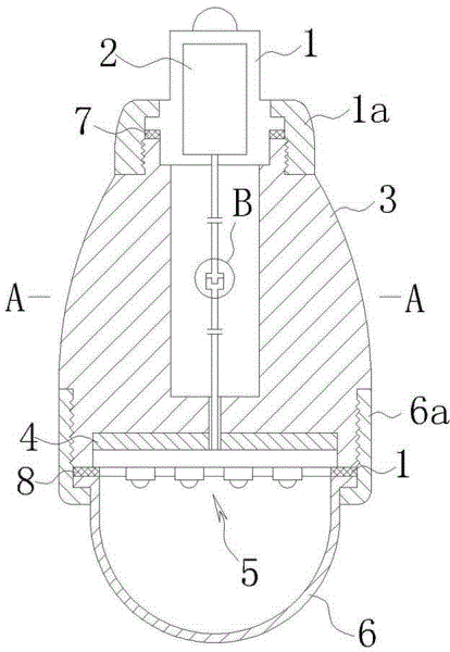
图1是本实用新型具体实施例一的结构示意图;Fig. 1 is the structural representation of the specific embodiment one of the utility model;
图2是图1中A-A处的剖视图;Fig. 2 is the sectional view of A-A place among Fig. 1;
图3是图1中B处的局部放大示意图;Fig. 3 is a partially enlarged schematic diagram of place B in Fig. 1;
图4是本实用新型具体实施例二的结构示意图;Fig. 4 is the structural representation of the second embodiment of the utility model;
图5是本实用新型具体实施例三的结构示意图。Fig. 5 is a schematic structural view of a third embodiment of the utility model.
图中:绝缘灯头1、上扣环1a、电源模块2、散热体3、导热片4、LED光源模组5、二次光学扩散罩或二次光学透镜6、下扣环6a、上防水胶圈7、下防水胶圈8、电源连接器9、插接头9a、插接座9b。In the figure:
具体实施方式Detailed ways
实施例1Example 1
参阅图1至图3所示,本实用新型的一种组合式LED灯泡,包括绝缘灯头1在绝缘灯头1内设有电源模块2;在绝缘灯头1下部外围设有上扣环1a,上扣环1a与散热体3螺纹连接,通过上扣环1a将绝缘灯头1固定在散热体3上;在绝缘灯头1与散热体3的接触部之间设有上防水胶圈7,防止灰尘及水进入灯具内部损坏内部电子组件;在本实施例中,散热体3外表面一体成型有呈幅射状的散热翼片,可以加强散热效果,根据实际需要,散热体3外表面也可以设置成间间隔;在散热体3下表面设有导热片4,在导热片4上设有LED光源模组5,在LED光源模组5外围的散热体3上设有二次光学扩散罩或二次光学透镜6,在散热体3与二次光学扩散罩或二次光学透镜6之间设有下防水胶圈8,同样是为了防止灰尘及水进入灯具内部损坏内部电子组件,二次光学扩散罩或二次光学透镜6和下防水胶圈8配合将LED光源模组5压紧在散热体3下表面;在二次光学扩散罩或二次光学透镜6上端部外围设有下扣环6a,下扣环6a与散热体3螺纹连接将二次光学扩散罩或二次光学透镜6固定在散热体3上,这种结构方便拆装;在电源模块2与LED光源模组5之间的连接电路上设有电源连接器9,电源连接器9由相对应的插接头9a和插接座9b构成,插接头9a和插接座9b分别设置在电源模块2和LED光源模组5的连接电路端部。Referring to Figures 1 to 3, a combined LED light bulb of the present invention includes an
具体使用时,当电源模块2出现故障需要更换时,只需要取下上扣环1a,并分离插接头9a和插接座9b,即可单独对电源模块2部分进行更换;当LED光源模组5出现故障需要更换时,只需要取下下扣环6a,并分离插接头9a和插接座9b,即可单独对LED光源模组5进行更换;上述的操作均非常方便,不需要整体更换灯具,使得其它有用的部件可以继续使用,大大降低了LED灯具的使用成本,也达到环保的目的。In specific use, when the
实施例2Example 2
参阅图3所示,本实用新型的一种组合式LED灯泡,其结构与实施例1基本相同,不同之处在于:绝缘灯头1与上扣环1a为一体成型的整体结构;二次光学扩散罩或二次光学透镜6与下扣环6a为一体成型的整体结构;这种结构更加方便灯具的安装,减少了加工及安装的工序。其使用效果与实施例1基本相同。Referring to Fig. 3, a combined LED light bulb of the present invention has basically the same structure as that of
实施例3Example 3
参阅图4所示,本实用新型的一种组合式LED灯泡,其结构与实施例1基本相同,不同之处在于:上扣环1a与散热体3通过螺丝固定连接。即在上扣环1a侧边沿周向开若干个通孔,并在散热体3侧壁与通孔相对的位置设置定位孔,通过螺丝连接固定。其使用效果与实施例1基本相同。Referring to Fig. 4, a combined LED light bulb of the present invention has basically the same structure as that of
Claims (10)
Priority Applications (1)
| Application Number | Priority Date | Filing Date | Title |
|---|---|---|---|
| CN2011200751040U CN202017931U (en) | 2011-03-21 | 2011-03-21 | Combined LED Bulb |
Applications Claiming Priority (1)
| Application Number | Priority Date | Filing Date | Title |
|---|---|---|---|
| CN2011200751040U CN202017931U (en) | 2011-03-21 | 2011-03-21 | Combined LED Bulb |
Publications (1)
| Publication Number | Publication Date |
|---|---|
| CN202017931U true CN202017931U (en) | 2011-10-26 |
Family
ID=44811601
Family Applications (1)
| Application Number | Title | Priority Date | Filing Date |
|---|---|---|---|
| CN2011200751040U Expired - Fee Related CN202017931U (en) | 2011-03-21 | 2011-03-21 | Combined LED Bulb |
Country Status (1)
| Country | Link |
|---|---|
| CN (1) | CN202017931U (en) |
Cited By (6)
| Publication number | Priority date | Publication date | Assignee | Title |
|---|---|---|---|---|
| CN103604050A (en) * | 2013-08-29 | 2014-02-26 | 莱特尔科技(深圳)有限公司 | Single-ended plug-in type light-emitting diode (LED) lamp |
| WO2014048022A1 (en) * | 2012-09-29 | 2014-04-03 | 深圳和而泰照明科技有限公司 | Led lamp |
| CN104948951A (en) * | 2015-05-28 | 2015-09-30 | 长治市华光光电科技集团有限公司 | LED bulb lamp free of screw fixing |
| CN105003845A (en) * | 2015-06-25 | 2015-10-28 | 吴静 | LED lamp bulb |
| CN105003847A (en) * | 2015-06-25 | 2015-10-28 | 吴静 | LED bulb with higher stability |
| CN105953084A (en) * | 2016-05-11 | 2016-09-21 | 东莞市联洲知识产权运营管理有限公司 | Waterproof LED lamp base device |
-
2011
- 2011-03-21 CN CN2011200751040U patent/CN202017931U/en not_active Expired - Fee Related
Cited By (6)
| Publication number | Priority date | Publication date | Assignee | Title |
|---|---|---|---|---|
| WO2014048022A1 (en) * | 2012-09-29 | 2014-04-03 | 深圳和而泰照明科技有限公司 | Led lamp |
| CN103604050A (en) * | 2013-08-29 | 2014-02-26 | 莱特尔科技(深圳)有限公司 | Single-ended plug-in type light-emitting diode (LED) lamp |
| CN104948951A (en) * | 2015-05-28 | 2015-09-30 | 长治市华光光电科技集团有限公司 | LED bulb lamp free of screw fixing |
| CN105003845A (en) * | 2015-06-25 | 2015-10-28 | 吴静 | LED lamp bulb |
| CN105003847A (en) * | 2015-06-25 | 2015-10-28 | 吴静 | LED bulb with higher stability |
| CN105953084A (en) * | 2016-05-11 | 2016-09-21 | 东莞市联洲知识产权运营管理有限公司 | Waterproof LED lamp base device |
Similar Documents
| Publication | Publication Date | Title |
|---|---|---|
| CN205640354U (en) | Tri -proof light with high -efficient lamp body heat radiation structure of external drive | |
| CN205372309U (en) | A kind of LED street light | |
| CN205447292U (en) | High -efficient low -loss LED lamp | |
| CN202082653U (en) | Columnar easy to combine LED bulbs | |
| CN202017980U (en) | Easy combination flat LED ceiling downlight | |
| CN201074744Y (en) | LED bar-shaped lamp with cooling function | |
| CN201330953Y (en) | High-power LED fluorescent lamp | |
| CN204717475U (en) | A kind of LED downlight | |
| WO2012149820A1 (en) | Led light bulb | |
| CN203549448U (en) | Led lamp tube | |
| CN203549702U (en) | A new type of LED bracket light | |
| CN201925767U (en) | LED light source module with independent heat dissipation structure | |
| CN201288976Y (en) | LED ceiling lamp | |
| CN201232983Y (en) | Heat radiator and LED lamp | |
| CN100593668C (en) | High-power LED street light fitting | |
| WO2015169198A1 (en) | Led light source module | |
| CN202501263U (en) | Light-emitting diode (LED) panel lamp | |
| CN205048181U (en) | LED drive power supply electricity -saving lamp | |
| CN205299134U (en) | LED bulb lamp | |
| CN202017930U (en) | A combined heat-dissipating LED downlight | |
| CN104100911A (en) | Outdoor LED lamp structure | |
| CN203082588U (en) | A 360° luminous LED imitation sodium lamp | |
| CN201983132U (en) | LED reflector lamp | |
| CN202118640U (en) | A new type of LED downlight | |
| CN205909012U (en) | LED three proofings frame lamp |
Legal Events
| Date | Code | Title | Description |
|---|---|---|---|
| C14 | Grant of patent or utility model | ||
| GR01 | Patent grant | ||
| C17 | Cessation of patent right | ||
| CF01 | Termination of patent right due to non-payment of annual fee |
Granted publication date: 20111026 Termination date: 20120321 |