CN201990448U - Automatic climbing machine for tower of wind generator - Google Patents
Automatic climbing machine for tower of wind generator Download PDFInfo
- Publication number
- CN201990448U CN201990448U CN2010206906680U CN201020690668U CN201990448U CN 201990448 U CN201990448 U CN 201990448U CN 2010206906680 U CN2010206906680 U CN 2010206906680U CN 201020690668 U CN201020690668 U CN 201020690668U CN 201990448 U CN201990448 U CN 201990448U
- Authority
- CN
- China
- Prior art keywords
- electromagnet
- grasping mechanism
- bar core
- tower tube
- wind generator
- Prior art date
- Legal status (The legal status is an assumption and is not a legal conclusion. Google has not performed a legal analysis and makes no representation as to the accuracy of the status listed.)
- Expired - Fee Related
Links
Images


Classifications
-
- Y—GENERAL TAGGING OF NEW TECHNOLOGICAL DEVELOPMENTS; GENERAL TAGGING OF CROSS-SECTIONAL TECHNOLOGIES SPANNING OVER SEVERAL SECTIONS OF THE IPC; TECHNICAL SUBJECTS COVERED BY FORMER USPC CROSS-REFERENCE ART COLLECTIONS [XRACs] AND DIGESTS
- Y02—TECHNOLOGIES OR APPLICATIONS FOR MITIGATION OR ADAPTATION AGAINST CLIMATE CHANGE
- Y02E—REDUCTION OF GREENHOUSE GAS [GHG] EMISSIONS, RELATED TO ENERGY GENERATION, TRANSMISSION OR DISTRIBUTION
- Y02E10/00—Energy generation through renewable energy sources
- Y02E10/70—Wind energy
- Y02E10/72—Wind turbines with rotation axis in wind direction
Abstract
An automatic climbing machine for a tower of a wind generator is provided with an operation plane and comprises a support. An upper electromagnetic grasping mechanism and a lower electromagnetic grasping mechanism are arranged on the support, positioned on the operation plane and connected by a retractable mechanism arranged between the upper electromagnetic grasping mechanism and the lower electromagnetic grasping mechanism. The iron characteristic of the tower are ingeniously used for attaching, fixing and climbing, the automatic climbing machine can be used for climbing other iron walls, and is rapid in operation and widely applied to maintenance operation of towers of wind generators or other components with iron surfaces.
Description
Technical field
The utility model relates to a kind of Fan Equipment and safeguards machinery, the automatic climbing machine of particularly a kind of auxiliary cleaning, maintenance wind generator tower tube.
Background technology
The wind generator tower tube is the irony structure, build in coastal, desert, bad weather area such as high and cold because wind energy turbine set, the Fan Equipment long term exposure out of doors, blower fan tower barrel is subjected to the erosion at sea wind, sand and dust, sunshine, cause tower tube external paint to peel off surface corrosion easily.So not only influence the attractive in appearance of aerogenerator, even can influence also that it is safe in utilization.Therefore, in time blower fan tower barrel is cleaned and repairs, helpful service life to improving the attractive in appearance of blower fan and prolonging the tower tube.
At present, the height of large fan tower tube from tens meters to rice up to a hundred, can not directly rely on the maintenance of tower tube outer surface and manually to climb operation and finish, so need use auxiliary elevating gear.Present stage to the anticorrosion maintenance of big blower fan tower barrel, is to utilize goliath to promote artificial cage to operate and finish basically on the market, maintenance cost height like this, and efficient is low, inconvenient operation, and the strictness of crane job site requirements.How to solve the tower tube high-altitude maintenance issues of aerogenerator, improve maintenance efficiency and be called a difficult problem that needs to be resolved hurrily.On the market some later-model automatic climbing machine is arranged now, it is double-layer structure ring support about adopting on tower tube outer cover, be provided with monitoring device and lifting operation parts, and then load onto along the tower tube axially and the hydraulic ram of radial arrangement, rely on the push-pull effort of hydraulic ram output and gripping power to realize the oscilaltion outside the tower tube step by step of two ring supports.But this apparatus structure bulky complex, the cost of production height not too is fit to extensive construction operation; In addition, the quilt climbing thing that it also is difficult to adapt to the perpendicular class makes its Applicable scope constriction greatly.
The utility model content
The purpose of this utility model is for a kind of wind generator tower tube automatic climbing machine is provided.
The solution that the utility model solves its technical matters is:
Wind generator tower tube automatic climbing machine, it has a driving surface, it comprises support, described support is provided with electromagnet grasping mechanism and lower electromagnet grasping mechanism, described upward electromagnet grasping mechanism and lower electromagnet grasping mechanism are positioned on the driving surface, the described telescoping mechanism that is provided with between electromagnet grasping mechanism and the lower electromagnet grasping mechanism the two connection of going up.
As further improvement in the technical proposal, the stack shell outside of described support and several sleeves is hinged, the stack shell internal sleeve of described sleeve is connected to the bar core, the shaft of described bar core connects with the fixed end of last electromagnet grasping mechanism and lower electromagnet grasping mechanism, the bar core is connected with adapter plate near an end of carriage center, and two up and down of described adapter plate is hinged with the movable end of last electromagnet grasping mechanism and lower electromagnet grasping mechanism respectively.
As further improvement in the technical proposal, described go up the electromagnet grasping mechanism comprise the upper bracket that is arranged on the superjacent air space on the adapter plate vertical direction, the adapter plate upper side to electromagnet on the driving surface, be arranged on the bar core bar on one's body on the bar core of side hinged seat and with described bar core on the flex link that couples together between hinged seat and the upper bracket, when the effective length of described flex link guaranteed that the vertical position of upper bracket changes, the bar core was in horizontality.
As further improvement in the technical proposal, described lower electromagnet grasping mechanism comprise the undersetting that is arranged on the adapter plate bottom, the adapter plate bottom surfaces to the lower electromagnet of driving surface, be arranged on hinged seat under the bar core below the bar core bar body and with described bar core under the lower connecting rod that couples together between hinged seat and the undersetting.
As further improvement in the technical proposal, described telescoping mechanism is the revolution leading screw that two ends connect with upper bracket and undersetting respectively; Perhaps be that the piston rod mouth connects with adapter plate, the terminal cylinder that connects with upper bracket of cylinder body.
Perhaps, improve as the another kind of technique scheme, the described electromagnet grasping mechanism of going up is: the stack shell outside of support and several upper bushes is hinged, but the inside of described upper bush be provided with elastic telescopic, front end is provided with the upper boom of electromagnet.
As further improvement in the technical proposal, described lower electromagnet grasping mechanism is: the following side space of upper bush is provided with lower sleeve, but described lower sleeve inside be provided with elastic telescopic, front end is provided with the lower beam of lower electromagnet, described lower sleeve is terminal hinged away from end of driving surface and upper bush, is provided with between the shaft of its stack shell and upper boom respectively and the two pivotally attached revolution leading screw.
As further improvement in the technical proposal, described support is provided with the slipping mechanism of slippage thereon.
The beneficial effects of the utility model are: the utility model is by being provided with electromagnet grasping mechanism and lower electromagnet grasping mechanism, when making the electromagnet energising generation magnetic force of its movable end, can be adsorbed on the outer wall of irony mechanism securely, firm with lower electromagnet grasping mechanism energising absorption earlier, move on the movable end of the last electromagnet grasping mechanism of telescoping mechanism elongation promotion, arrive the electromagnet energising of going up the electromagnet grasping mechanism behind the fixed step size and adsorb the irony outer wall, the electric power that disconnects the lower electromagnet grasping mechanism unclamps by its movable end, then telescoping mechanism withdrawal, traction lower electromagnet grasping mechanism also with on move, energising absorption is firm again after arriving a fixed step size, so just, realized the action of climbing of support, only need control outer detection and the work of cleaning element that is located on the support when the time comes, can be to irony mechanism, particularly the wind generator tower tube carries out the outer wall operation; When support need land, only need anti-operation above-mentioned steps to get final product.
The utility model adopts the fixing version of electromagnet absorption is set, integral structure is light and handy, low cost of manufacture, safe, not only can significantly improve blower fan tower barrel outside face maintenance efficiency, and good popularization and application prospect also be arranged in external wall of high-rise building cleaning, anticorrosion of steel structure field.
Description of drawings
Below in conjunction with drawings and Examples the utility model is further described.
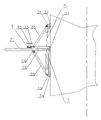
Fig. 1 is the structure principle chart of embodiment 1 of the present utility model, and wherein telescoping mechanism adopts the revolution leading screw;
Fig. 2 is the birds-eye view of Fig. 1;
Fig. 3 is the another kind of structure principle chart of embodiment 1 of the present utility model, and wherein telescoping mechanism adopts cylinder;
Fig. 4 is the structure principle chart of embodiment 2 of the present utility model, and wherein the front end of lower beam is connected with lower electromagnet;
Fig. 5 is the birds-eye view of Fig. 4;
Fig. 6 is the structure birds-eye view of embodiment 3 of the present utility model.
The specific embodiment
With reference to Fig. 1~Fig. 3, wind generator tower tube automatic climbing machine, comprise surrounding and be arranged on the outer support 1 of tower tube, be provided with electromagnet grasping mechanism and lower electromagnet grasping mechanism between described support 1 and the tower tube, the described electromagnet grasping mechanism and lower electromagnet grasping mechanism dependence magnetic force and tower drum outer wall gone up freely switches absorption and the state that unclamps, the described telescoping mechanism that is provided with between electromagnet grasping mechanism and the lower electromagnet grasping mechanism the two connection of going up.Can be provided for detecting element on the support 1 with cleaning.In order to strengthen steadiness and convenient other operation elements of installing, can adopt the structure that multilayer support 1 is installed; Can also install latching device additional on frame 1, when the abnormal power-down situation occurring, the latching device auto lock guarantees location, machine high-altitude, increases safety; In addition, if support 1 is made smooth strip structure, can also rely on power-on and power-off magnet grasping mechanism to be adsorbed on the irony wall (as Curtain wall frame) on plane.
Be the improvement that the utility model is done as embodiment 1 below, adsorbed driving surface is the irony tower drum outer wall:
With reference to Fig. 1~Fig. 2, described support 1 integral body in the form of a ring, itself and several rod axis points to sleeve 21 outside hinged of tower tube central axis, the internal sleeve of described sleeve 21 is connected to bar core 22, the shaft of described bar core 22 connects with the fixed end of last electromagnet grasping mechanism and lower electromagnet grasping mechanism, bar core 22 connects with the adapter plate 3 that is arranged on the tower tube outer surface near an end of tower tube, and two up and down of described adapter plate 3 is hinged with the movable end of last electromagnet grasping mechanism and lower electromagnet grasping mechanism respectively.Particularly, described sleeve 21 has six, and equidistantly the axis around the tower tube distributes; Described adapter plate 3 also is provided with the rubber cushion blocks 35 that is used to alleviate collision friction and plays buffer action in a side that is adjacent to the tower tube, and rubber-like rubber cushion blocks 35 can also remedy between the rising tapering of tower tube itself and the vertical adapter plate 3 minim gap of generation gradually.
Be further used as preferred embodiment, described go up the electromagnet grasping mechanism comprise the upper bracket 31 that is arranged on the superjacent air space on adapter plate 3 vertical directions, electromagnet 32 on the top of adapter plate 3 applying tower tubes one side, be arranged on hinged seat 23 on the bar core above bar core 22 shafts and with described bar core on the flex link that couples together between hinged seat 23 and the upper bracket 31, when the effective length of described flex link guaranteed that the vertical position of upper bracket 31 changes, bar core 22 was in horizontality.Particularly, described flex link be length controlled, with the steel rope 36 that hinged seat on the bar core 23 and upper bracket 31 tractions are got up, its length rolling is controlled by miniature motor, the outer end of guaranteeing to hold bar core 22 and sleeve 21 does not allow its canting.
Be further used as preferred embodiment, described lower electromagnet grasping mechanism comprise the undersetting 33 that is arranged on adapter plate 3 bottoms, the lower electromagnet 34 of the bottom of adapter plate 3 applying tower tubes one side, be arranged on hinged seat 24 under the bar core below bar core 22 shafts and with described bar core under the lower connecting rod 35 that couples together between hinged seat 24 and the undersetting 33.Like this, bar core 22, lower connecting rod 35 and adapter plate 3 have just constituted an English truss, when telescoping mechanism is flexible, and just this English truss of stretchy, and even support 1 whole upper and lower translation.
With reference to Fig. 3, be further used as preferred embodiment, described telescoping mechanism is the revolution leading screw 5 that two ends connect with upper bracket 31 and undersetting 33 respectively; Perhaps be that the piston rod mouth connects with adapter plate 3, the terminal cylinder 6 that connects with upper bracket 31 of cylinder body.
Be further used as preferred embodiment, also be provided with slipping mechanism on the described support 1.Particularly, on support 1, guide rail is set, described slipping mechanism is the slide block 15 that is linked on this guide rail, on slide block 15, control monitor unit and attending device can be set, when control monitor unit and attending device need positioning operation, slide block 15 can cooperate around the guide rail rotation, does location selectively, carries out construction operation.
Be the workflow of embodiment 1 below: the peripheral equipment of the utility model at the tower tube bottom prepared, and make its minimum altitude avoid manhole; At first allow lower electromagnet 34 switch on, last electromagnet 32 outages, the English truss of bar core 22, lower connecting rod 35 and adapter plate 3 formation just is fixed on tower tube periphery like this; Then turn round 6 actions of leading screw 5 or cylinder, drive upper bracket 31 and last electromagnet 32 upwards translations, the steel rope that connects between the hinged seat 23 is pressed progressively unwrapping wire of feeding degree on upper bracket 31 and the bar core simultaneously, guarantees that itself is in tensioned state always; After arriving certain step-length, last electromagnet 32 energisings produce suction adsorption at tower drum outer wall, revolution leading screw 5 or cylinder 6 actions, drive the whole upwards translation of the described English truss distance of step-length just now, steel rope guarantees that by the progressively take-up of feeding degree itself is in tensioned state always simultaneously.So just, finished a step of upwards climbing, repeat this step, power-on and power-off magnet alternate energisation, middle telescoping mechanism is alternately flexible, just can on the tower tube, drive support 1 automatic climbing, after the specified altitude assignment of climbing, operating personal passes through camera head monitor blower fan stack shell apparent order and condition on ground, man-machine interface by the upper computer computer, the action of control lower computer PLC power-on and power-off magnet grasping mechanism and telescoping mechanism, driving the utility model climbs and descends, and control slide block 15 rotates to specified angle, operations such as the operation element on it just can clean, maintenance.
When needs land the utility model, only need the contrary operation above-mentioned steps, because the doughnut structure of support 1 itself adds the support of lower electromagnet 34, the traction of steel rope, guaranteed support 1 can be in dropping process outwards canting, can progressively climb downwards equally.
Be the improvement that the utility model is done as embodiment 2 below, adsorbed driving surface is the irony tower drum outer wall:
With reference to Fig. 4~Fig. 5, described support 1 integral body in the form of a ring, the described electromagnet grasping mechanism of going up is: support 1 and several rod axis point to upper bush 25 outside hinged of tower tube central axis, but the inside of described sleeve 25 be provided with elastic telescopic, front end is provided with the upper boom 26 of electromagnet 32.Particularly, described sleeve 25 has six, and the periphery that equidistantly is centered around the tower tube distributes.The outside end sealing of upper bush 25, the rear end that spring and upper boom 26 are set in inside then leans, and can guarantee that so just electromagnet 32 is at any time near the conical outer wall of tower tube.
Be further used as preferred embodiment, described lower electromagnet grasping mechanism is: 21 times side spaces of sleeve are provided with lower sleeve 27, but described lower sleeve 27 inside be provided with elastic telescopic, front end is provided with the lower beam 28 of lower electromagnet 34, described lower sleeve 27 is terminal hinged away from end of tower tube and upper bush 25, is provided with between the shaft of its stack shell and upper boom 26 respectively and the two pivotally attached revolution leading screw 5.It is the same that the flexible form of lower sleeve 27 is caught up with sleeve 25, all adopts inner the mode that spring leans to be set, and allows lower electromagnet 34 at any time near the conical outer wall of tower tube.During 5 rotations of revolution leading screw, can realize the opening and closing of upper boom 26 and lower beam 28.
Be further used as preferred embodiment, also be provided with slipping mechanism on the described support 1.The form of implementation of slipping mechanism is identical with embodiment's 1.
Be that embodiment 2(present embodiment 2 is provided with two-layer support 1 below) workflow:
The peripheral equipment of the utility model at the tower tube bottom prepared, and make its minimum altitude avoid manhole; At first allow lower electromagnet 34 switch on, last electromagnet 32 outages; Then turn round leading screw 5 actions, elongation also drives upper boom 26 related upward electromagnet 32 upwards translations; After reaching a fixed step size, last electromagnet 32 energisings firmly are adsorbed on tower drum outer wall; Lower electromagnet 34 outages then, the stationary state cancellation of lower beam 28,5 rotations of revolution leading screw are shunk, and drive lower electromagnet 34 related lower beams 28 and upwards promote lower electromagnet 34 energisings after arriving described step-length, again adsorb tower drum outer wall, so just, finished a step of upwards climbing, repeated this step, power-on and power-off magnet alternate energisation, middle telescoping mechanism is alternately flexible, just can drive support 1 automatic climbing on the tower tube.The inverse operation above-mentioned steps, the utility model can land downwards.During upkeep operation, electromagnet is switched on simultaneously and is fixed in the stack shell outside.
With reference to Fig. 6, as embodiment 3 of the present utility model, adsorbed driving surface is the outer wall of irony Curtain wall frame.If support 1 is designed to the bench board of strip, slipping mechanism is arranged on the bench board, utilize the last electromagnet grasping mechanism of the above embodiments 1 and embodiment 2 and the form of implementation of lower electromagnet grasping mechanism, the mode that can adopt alternate energisation, telescoping mechanism to stretch equally realizes climbing on a vertical plane, when climbing fixed point, firm by last electromagnet 32 and lower electromagnet 34 energising absorption, constitute triangular support bracket, support 1 can be fixed on the body of wall outer wall, then by top set monitoring, safeguard element work.
More than be that better embodiment of the present utility model is specified, but the invention is not limited to described embodiment, those of ordinary skill in the art also can make all equivalent variations or replacement under the prerequisite of the utility model spirit, modification that these are equal to or replacement all are included in the application's claim institute restricted portion.
Claims (8)
1. wind generator tower tube automatic climbing machine, it has a driving surface, it is characterized in that: it comprises support (1), described support (1) is provided with electromagnet grasping mechanism and lower electromagnet grasping mechanism, described upward electromagnet grasping mechanism and lower electromagnet grasping mechanism are positioned on the driving surface, the described telescoping mechanism that is provided with between electromagnet grasping mechanism and the lower electromagnet grasping mechanism the two connection of going up.
2. wind generator tower tube automatic climbing machine according to claim 1, it is characterized in that: described support (1) is hinged with the stack shell outside of several sleeves (21), the stack shell internal sleeve of described sleeve (21) is connected to bar core (22), the shaft of described bar core (22) connects with the fixed end of last electromagnet grasping mechanism and lower electromagnet grasping mechanism, bar core (22) is connected with adapter plate (3) near an end at support (1) center, and two up and down of described adapter plate (3) is hinged with the movable end of last electromagnet grasping mechanism and lower electromagnet grasping mechanism respectively.
3. wind generator tower tube automatic climbing machine according to claim 2, it is characterized in that: the described electromagnet grasping mechanism of going up comprises the upper bracket (31) that is arranged on the superjacent air space on adapter plate (3) vertical direction, be positioned at the last electromagnet (32) of adapter plate (3) upper side to driving surface, be arranged on the bar core of bar core (22) shaft top hinged seat (23) and with the flex link that couples together between hinged seat (23) on the described bar core and the upper bracket (31), when the effective length of described flex link guaranteed that the vertical position of upper bracket (31) changes, bar core (22) was in horizontality.
4. wind generator tower tube automatic climbing machine according to claim 2 is characterized in that: described lower electromagnet grasping mechanism comprises the undersetting (33) that is arranged on adapter plate (3) bottom, be positioned at adapter plate (3) bottom surfaces to the lower electromagnet (34) of driving surface, be arranged on hinged seat (24) under the bar core of bar core (22) shaft below and with described bar core under the lower connecting rod (35) that couples together between hinged seat (24) and the undersetting (33).
5. according to claim 1,2,3 or 4 described wind generator tower tube automatic climbing machines, it is characterized in that: described telescoping mechanism is the revolution leading screw (5) that two ends connect with upper bracket (31) and undersetting (33) respectively; Perhaps be that the piston rod mouth connects with adapter plate (3), the terminal cylinder (6) that connects with upper bracket (31) of cylinder body.
6. wind generator tower tube automatic climbing machine according to claim 1, it is characterized in that: the described electromagnet grasping mechanism of going up is: support (1) is hinged with the stack shell outside of several upper bushes (25), described upper bush (25) but inside be provided with elastic telescopic, front end is provided with the upper boom (26) of electromagnet (32).
7. according to claim 1 or 6 described wind generator tower tube automatic climbing machines, it is characterized in that: described lower electromagnet grasping mechanism is: the following side space of upper bush (25) is provided with lower sleeve (27), described lower sleeve (27) but inside be provided with elastic telescopic, front end is provided with the lower beam (28) of lower electromagnet (34), described lower sleeve (27) is terminal hinged away from end of driving surface and upper bush (25), is provided with between the shaft of its stack shell and upper boom (26) respectively and the two pivotally attached revolution leading screw (5).
8. according to claim 1,2 or 6 described wind generator tower tube automatic climbing machines, it is characterized in that: described support (1) is provided with the slipping mechanism of slippage thereon.
Priority Applications (1)
| Application Number | Priority Date | Filing Date | Title |
|---|---|---|---|
| CN2010206906680U CN201990448U (en) | 2010-12-30 | 2010-12-30 | Automatic climbing machine for tower of wind generator |
Applications Claiming Priority (1)
| Application Number | Priority Date | Filing Date | Title |
|---|---|---|---|
| CN2010206906680U CN201990448U (en) | 2010-12-30 | 2010-12-30 | Automatic climbing machine for tower of wind generator |
Publications (1)
| Publication Number | Publication Date |
|---|---|
| CN201990448U true CN201990448U (en) | 2011-09-28 |
Family
ID=44666942
Family Applications (1)
| Application Number | Title | Priority Date | Filing Date |
|---|---|---|---|
| CN2010206906680U Expired - Fee Related CN201990448U (en) | 2010-12-30 | 2010-12-30 | Automatic climbing machine for tower of wind generator |
Country Status (1)
| Country | Link |
|---|---|
| CN (1) | CN201990448U (en) |
Cited By (6)
| Publication number | Priority date | Publication date | Assignee | Title |
|---|---|---|---|---|
| CN102126689A (en) * | 2010-12-30 | 2011-07-20 | 广东力特工程机械有限公司 | Automatic climbing machine for wind driven generator tower |
| CN104832377A (en) * | 2015-05-15 | 2015-08-12 | 湖南大学 | Clamping jaw for tower drum outer wall maintenance platform |
| CN105065213A (en) * | 2015-09-07 | 2015-11-18 | 辽宁大金重工股份有限公司 | Self-elevating tower maintaining platform |
| CN105858554A (en) * | 2016-06-03 | 2016-08-17 | 江苏科技大学 | Self-lifting platform used for maintaining wind power tower tube outer wall |
| CN112370679A (en) * | 2020-11-05 | 2021-02-19 | 国网河南省电力公司武陟县供电公司 | Special stores pylon of outdoor 35kV circuit breaker aerial work safety belt |
| CN112624008A (en) * | 2020-12-03 | 2021-04-09 | 李晓诠 | Electric power tool car |
-
2010
- 2010-12-30 CN CN2010206906680U patent/CN201990448U/en not_active Expired - Fee Related
Cited By (8)
| Publication number | Priority date | Publication date | Assignee | Title |
|---|---|---|---|---|
| CN102126689A (en) * | 2010-12-30 | 2011-07-20 | 广东力特工程机械有限公司 | Automatic climbing machine for wind driven generator tower |
| CN104832377A (en) * | 2015-05-15 | 2015-08-12 | 湖南大学 | Clamping jaw for tower drum outer wall maintenance platform |
| CN105065213A (en) * | 2015-09-07 | 2015-11-18 | 辽宁大金重工股份有限公司 | Self-elevating tower maintaining platform |
| CN105858554A (en) * | 2016-06-03 | 2016-08-17 | 江苏科技大学 | Self-lifting platform used for maintaining wind power tower tube outer wall |
| CN112370679A (en) * | 2020-11-05 | 2021-02-19 | 国网河南省电力公司武陟县供电公司 | Special stores pylon of outdoor 35kV circuit breaker aerial work safety belt |
| CN112370679B (en) * | 2020-11-05 | 2022-02-01 | 国网河南省电力公司武陟县供电公司 | Special stores pylon of outdoor 35kV circuit breaker aerial work safety belt |
| CN112624008A (en) * | 2020-12-03 | 2021-04-09 | 李晓诠 | Electric power tool car |
| CN112624008B (en) * | 2020-12-03 | 2022-06-24 | 李晓诠 | Electric power tool car |
Similar Documents
| Publication | Publication Date | Title |
|---|---|---|
| CN102126689B (en) | Automatic climbing machine for wind driven generator tower | |
| CN201990448U (en) | Automatic climbing machine for tower of wind generator | |
| CN105476560A (en) | Wall surface cleaning robot and control method thereof | |
| CN108808542B (en) | Power transmission line broken strand repairing robot mechanism | |
| CN203064069U (en) | Dynamic climbing device of tower | |
| CN108808577B (en) | Power transmission line broken strand repairing tool | |
| CN107061173B (en) | A kind of Intelligent wind driven generator | |
| CN106992745A (en) | A kind of photovoltaic power generation equipment for improving capability of anti-wind | |
| CN202220665U (en) | Wind power generator wheel hub component maintaining and changing device and wind power generator thereof | |
| CN105774934A (en) | Vertical travelling mechanism for wind tower maintenance robot | |
| CN101259857A (en) | Electric-drive creeping type cable robot | |
| CN101786586B (en) | Large-diameter cylinder body outer wall climbing device | |
| CN104828752A (en) | Traction suspension device for fan repair | |
| CN209600748U (en) | A kind of offshore wind turbine cushion cap Active Compensation steps on quadrupler | |
| CN214347398U (en) | Tower section of thick bamboo application equipment | |
| CN205554359U (en) | Wind power tower cylinder maintains upper and lower running gear of robot | |
| CN208693150U (en) | A kind of exterior wall cleaning robot for skyscraper | |
| CN203529784U (en) | Wind power maintenance machine | |
| CN205620389U (en) | Air monitoring device based on thing networking | |
| CN213879245U (en) | Linkage device for lifting of lightning receptor and anemometer | |
| CN211116428U (en) | Wind power tower fan blade maintenance integrated machine | |
| CN211847065U (en) | Novel wind power operation and maintenance loop type platform | |
| CN107859960A (en) | A kind of wind power generation streetlamp for being easy to maintenance suitable for coastal area | |
| CN103539020A (en) | Novel hoisting construction method and special hanging device | |
| CN114180472A (en) | Large-displacement telescopic self-climbing wind power hoisting device and method |
Legal Events
| Date | Code | Title | Description |
|---|---|---|---|
| C14 | Grant of patent or utility model | ||
| GR01 | Patent grant | ||
| C17 | Cessation of patent right | ||
| CF01 | Termination of patent right due to non-payment of annual fee |
Granted publication date: 20110928 Termination date: 20131230 |