CN201980881U - Lifting part of hydraulic bracket installation machine - Google Patents
Lifting part of hydraulic bracket installation machine Download PDFInfo
- Publication number
- CN201980881U CN201980881U CN 201120092222 CN201120092222U CN201980881U CN 201980881 U CN201980881 U CN 201980881U CN 201120092222 CN201120092222 CN 201120092222 CN 201120092222 U CN201120092222 U CN 201120092222U CN 201980881 U CN201980881 U CN 201980881U
- Authority
- CN
- China
- Prior art keywords
- rotating disk
- hydraulic
- square structure
- crank
- fixed
- Prior art date
- Legal status (The legal status is an assumption and is not a legal conclusion. Google has not performed a legal analysis and makes no representation as to the accuracy of the status listed.)
- Expired - Fee Related
Links
- 238000009434 installation Methods 0.000 title abstract description 5
- 239000000725 suspension Substances 0.000 claims description 12
- 239000003245 coal Substances 0.000 abstract description 3
- 238000005065 mining Methods 0.000 description 4
- 238000005516 engineering process Methods 0.000 description 2
- 230000009286 beneficial effect Effects 0.000 description 1
- 230000007812 deficiency Effects 0.000 description 1
Images

Landscapes
- Load-Engaging Elements For Cranes (AREA)
Abstract
The utility model relates to a lifting part of a hydraulic bracket installation machine, which belongs to the technical field of a coal mine underground crane, and the lifting part is capable of being convenient to lift a hydraulic bracket and adjusting a position and an angle of the hydraulic bracket. The adopted technical scheme is that the lifting part comprises a bracket body in a square structure, a turning plate cylinder, a crank, a turning plate, a rotating table, winches, lifting hooks and a micro hydraulic motor. A groove is arranged on the top of the bracket body in the square structure, the turning plate is arranged in the groove, a cylinder body of the turning plate cylinder is in hinge connection with an edge of the top of the bracket body in the square structure, a piston rod of the turning plate cylinder is in hinge connection with one end of the crank, the other end of the crank is fixed on the top of the turning plate, the rotating table is fixed on the bottom of the turning plate through a connection cylinder, four winches are fixed on the rotating table, and each winch is connected with one lifting hook through a rope. The lifting part of the hydraulic bracket installation machine is used for lifting the hydraulic bracket and adjusting the position and the angle of the hydraulic bracket.
Description
Technical field
The lifting part of the utility model hydraulic support fitting machine belongs to crane technical field under the coal mine.
Background technology
At present, the hydraulic support of fully-mechanized mining working when mounted under most of coal mine, all need with the transport to fully-mechanized mining working of mine car a platform of hydraulic support, in place with chain sling and ways such as winch and a dead lift then by platform, fully-mechanized mining working has the hydraulic support about 150, adorns what a fully-mechanized mining working time spent to get inefficiency nearly one month, expended the plenty of time, working strength of workers is also very big.
The utility model content
The utility model overcomes the deficiencies in the prior art, technical matters to be solved is for providing a kind of lifting part of hydraulic support fitting machine, the hydraulic support of can slinging easily, and can adjust the position and the angle of hydraulic support, save the set-up time of hydraulic support, reduced working strength of workers.
In order to solve the problems of the technologies described above, the technical solution adopted in the utility model is: the lifting part of hydraulic support fitting machine, comprise the square structure support body, the rotating disk oil cylinder, crank, rotating disk, turntable, winch, suspension hook and micro-hydraulic motor, the top of square structure support body is provided with groove, rotating disk is arranged in described groove, the edge at the cylinder body of rotating disk oil cylinder and square structure support body top is hinged, one end of the piston rod of rotating disk oil cylinder and crank is hinged, the other end of crank is fixed on the top of rotating disk, the bottom of rotating disk is fixed with turntable by joint pin, be fixed with four winchs on the turntable, each winch is connected with a suspension hook by rope.
Four micro-hydraulic motors are separately fixed on four angles of square structure support body, gear all is installed on the output shaft of each micro-hydraulic motor, the square structure support body is arranged between two cantilever beams, two roller chains are installed in respectively on two cantilever beams, and micro-hydraulic motor is installed on the roller chain by gear.
The utility model compared with prior art has following beneficial effect.
1, is fixed with four winchs on the turntable of the present utility model, each winch is connected with a suspension hook by rope, the hydraulic support of can slinging, the edge at the cylinder body of rotating disk oil cylinder and square structure support body top is hinged, one end of the piston rod of rotating disk oil cylinder and crank is hinged, and the other end of crank is fixed on the top of rotating disk, and the bottom of rotating disk is fixed with turntable by joint pin, the rotating disk oil cylinder drives turntable by rotating disk and rotates in the certain angle scope, allows hydraulic support rest on proper angle.
2, roller chain is arranged on the cantilever beam, four micro-hydraulic motors are separately fixed on four angles of square structure support body, on the output shaft of micro-hydraulic motor gear is installed, micro-hydraulic motor is installed on the roller chain by gear, the utility model can laterally move on cantilever beam by micro-hydraulic motor, allows hydraulic support arrive suitable installation site.
Description of drawings
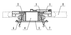
Fig. 1 is the structural representation of the lifting part of the utility model hydraulic support fitting machine.
Fig. 2 is the birds-eye view of Fig. 1.
Among the figure: 1 is that square structure support body, 2 is that rotating disk, 3 is that rotating disk oil cylinder, 4 is that joint pin, 5 is that turntable, 6 is that winch, 7 is that suspension hook, 8 is that cantilever beam, 9 is that micro-hydraulic motor, 10 is that crank, 11 is a roller chain.
The specific embodiment
As Fig. 1, shown in Figure 2, the lifting part of the utility model hydraulic support fitting machine, comprise square structure support body 1, rotating disk oil cylinder 3, crank 10, rotating disk 2, turntable 5, winch 6, suspension hook 7 and micro-hydraulic motor 9, the top of square structure support body 1 is provided with groove, rotating disk 2 is arranged in described groove, the edge at the cylinder body of rotating disk oil cylinder 3 and square structure support body 1 top is hinged, one end of the piston rod of rotating disk oil cylinder 3 and crank 10 is hinged, the other end of crank 10 is fixed on the top of rotating disk 2, the bottom of rotating disk 2 is fixed with turntable 5 by joint pin 4, be fixed with four winchs 6 on the turntable 5, each winch 6 is connected with a suspension hook 7 by rope.
Four micro-hydraulic motors 9 are separately fixed on four angles of square structure support body 1, gear all is installed on the output shaft of each micro-hydraulic motor 9, square structure support body 1 is arranged between two cantilever beams 8, two roller chains 11 are installed in respectively on two cantilever beams 8, and micro-hydraulic motor 9 is installed on the roller chain 11 by gear.
Winch 6 of the present utility model is sling hydraulic support by suspension hook 7 under the drive of HM Hydraulic Motor.
The utility model relies on four micro-hydraulic motors 9 that are separately fixed on 1 four angles of square structure support body, side travel on the roller chain 11 of two cantilever beams 8, and the hydraulic support that will be sling moves to suitable installation site.
The piston rod of rotating disk oil cylinder 3 of the present utility model is done fore and aft motion, driving rotating disk 2 by crank 10 rotates in 90 degree scopes, turntable 5 is also rotating in 90 degree scopes under the drive of rotating disk 2, and by the rotation of turntable 5, the hydraulic support that will be sling puts down after rotating to after the proper angle.
The workflow of the lifting part of the utility model hydraulic support fitting machine is: the utility model is installed on the cantilever beam 8 of hydraulic support fitting machine, hydraulic support is positioned over the utility model below, handling four winchs 6 transfers suspension hook 7, after hooking hydraulic support with suspension hook 7, handling winch 6 slings hydraulic support, operating hydraulically operated then timbering machine arrives the position of shelving of driving surface, handling micro-hydraulic motor 9 moves the utility model on the roller chain 11 of cantilever beam 8, drive hydraulic support and arrive correct position, maneuvering dial oil cylinder 3 makes hydraulic support rotation proper angle, handle winch 6 suspension hook 7 is transferred, hydraulic support is put down.
Claims (1)
1. the lifting part of hydraulic support fitting machine, it is characterized in that: comprise square structure support body (1), rotating disk oil cylinder (3), crank (10), rotating disk (2), turntable (5), winch (6), suspension hook (7) and micro-hydraulic motor (9), the top of square structure support body (1) is provided with groove, rotating disk (2) is arranged in described groove, the edge at the cylinder body of rotating disk oil cylinder (3) and square structure support body (1) top is hinged, one end of the piston rod of rotating disk oil cylinder (3) and crank (10) is hinged, the other end of crank (10) is fixed on the top of rotating disk (2), the bottom of rotating disk (2) is fixed with turntable (5) by joint pin (4), be fixed with four winchs (6) on the turntable (5), each winch (6) is connected with a suspension hook (7) by rope;
Four micro-hydraulic motors (9) are separately fixed on four angles of square structure support body (1), on the output shaft of each micro-hydraulic motor (9) gear is installed all, square structure support body (1) is arranged between two cantilever beams (8), two roller chains (11) are installed in respectively on two cantilever beams (8), and micro-hydraulic motor (9) is installed on the roller chain (11) by gear.
Priority Applications (1)
| Application Number | Priority Date | Filing Date | Title |
|---|---|---|---|
| CN 201120092222 CN201980881U (en) | 2011-04-01 | 2011-04-01 | Lifting part of hydraulic bracket installation machine |
Applications Claiming Priority (1)
| Application Number | Priority Date | Filing Date | Title |
|---|---|---|---|
| CN 201120092222 CN201980881U (en) | 2011-04-01 | 2011-04-01 | Lifting part of hydraulic bracket installation machine |
Publications (1)
| Publication Number | Publication Date |
|---|---|
| CN201980881U true CN201980881U (en) | 2011-09-21 |
Family
ID=44608345
Family Applications (1)
| Application Number | Title | Priority Date | Filing Date |
|---|---|---|---|
| CN 201120092222 Expired - Fee Related CN201980881U (en) | 2011-04-01 | 2011-04-01 | Lifting part of hydraulic bracket installation machine |
Country Status (1)
| Country | Link |
|---|---|
| CN (1) | CN201980881U (en) |
Cited By (4)
| Publication number | Priority date | Publication date | Assignee | Title |
|---|---|---|---|---|
| CN102562101A (en) * | 2012-01-06 | 2012-07-11 | 山东兖煤精益机电设备有限公司 | Machine-mounted steel beam supporting device |
| CN102619540A (en) * | 2012-04-26 | 2012-08-01 | 山西东华机械有限公司 | Hydraulic support placing machine turntable device |
| CN103231986A (en) * | 2013-04-25 | 2013-08-07 | 山西东华机械有限公司 | Trolley structure for travelling crane |
| CN111332933A (en) * | 2020-04-02 | 2020-06-26 | 安徽钟南人防工程防护设备有限公司 | Hoisting mechanism for civil air defense door production |
-
2011
- 2011-04-01 CN CN 201120092222 patent/CN201980881U/en not_active Expired - Fee Related
Cited By (6)
| Publication number | Priority date | Publication date | Assignee | Title |
|---|---|---|---|---|
| CN102562101A (en) * | 2012-01-06 | 2012-07-11 | 山东兖煤精益机电设备有限公司 | Machine-mounted steel beam supporting device |
| CN102619540A (en) * | 2012-04-26 | 2012-08-01 | 山西东华机械有限公司 | Hydraulic support placing machine turntable device |
| CN102619540B (en) * | 2012-04-26 | 2014-06-18 | 山西东华机械有限公司 | Hydraulic support placing machine turntable device |
| CN103231986A (en) * | 2013-04-25 | 2013-08-07 | 山西东华机械有限公司 | Trolley structure for travelling crane |
| CN103231986B (en) * | 2013-04-25 | 2016-03-16 | 山西东华机械有限公司 | A kind of driving vehicle structure |
| CN111332933A (en) * | 2020-04-02 | 2020-06-26 | 安徽钟南人防工程防护设备有限公司 | Hoisting mechanism for civil air defense door production |
Similar Documents
| Publication | Publication Date | Title |
|---|---|---|
| CN102134043B (en) | Crawler hydraulic support assembling machine | |
| CN105293315B (en) | A kind of hanging device of assembled architecture prefabricated components | |
| CN201660296U (en) | Improved conveyer | |
| CN202201645U (en) | Gantry crane for subway construction | |
| CN205114894U (en) | Manual formula wall type swing crane; derrick | |
| CN101929346B (en) | Hydraulic bracket assembling and disassembling machine with supporting upright column | |
| CN101936176A (en) | Hydraulic bracket assembling machine | |
| CN208037868U (en) | A kind of formwork of bridge rail peace is torn open and transfer device | |
| CN203875330U (en) | Steel ladle covering device | |
| CN202575758U (en) | Roof covering lift | |
| CN109795947A (en) | A kind of prefabricated piping lane segment overturning suspender and method for turning | |
| CN202379648U (en) | Portable mobile crane | |
| CN102120548A (en) | Hydraulic telescopic suspension arm | |
| CN201980887U (en) | Crawler-type hydraulic-bracket crane trolley | |
| CN202038825U (en) | Hydraulic rotating suspension arm | |
| CN201694778U (en) | Downhole hydraulic support assembling and disassembling crane | |
| CN203065095U (en) | Slag pot lifting device | |
| CN102966318B (en) | Marine riser hoisting device | |
| CN106276624A (en) | A kind of mobilecrane with walking dolly and hoisting gear | |
| CN201990172U (en) | Multidirectional drive wheel transmission system of lifting platform truck | |
| CN201176372Y (en) | Novel demountable traveling mast crane | |
| CN205063835U (en) | Novel hydraulic drive derrick mechanism | |
| CN202991071U (en) | Device for replacing hydraulic support upright column of fully mechanized coal mining face of underground coal mine | |
| CN202784882U (en) | Manual mechanical oil-pouring device | |
| CN202609828U (en) | Mine full-hydraulic sling cart |
Legal Events
| Date | Code | Title | Description |
|---|---|---|---|
| C14 | Grant of patent or utility model | ||
| GR01 | Patent grant | ||
| CF01 | Termination of patent right due to non-payment of annual fee |
Granted publication date: 20110921 Termination date: 20180401 |
|
| CF01 | Termination of patent right due to non-payment of annual fee |