CN201934411U - Energy-saving pressure relief valve of hydraulic system - Google Patents
Energy-saving pressure relief valve of hydraulic system Download PDFInfo
- Publication number
- CN201934411U CN201934411U CN2011200368195U CN201120036819U CN201934411U CN 201934411 U CN201934411 U CN 201934411U CN 2011200368195 U CN2011200368195 U CN 2011200368195U CN 201120036819 U CN201120036819 U CN 201120036819U CN 201934411 U CN201934411 U CN 201934411U
- Authority
- CN
- China
- Prior art keywords
- valve
- energy
- liquid
- hydraulic system
- main valve
- Prior art date
- Legal status (The legal status is an assumption and is not a legal conclusion. Google has not performed a legal analysis and makes no representation as to the accuracy of the status listed.)
- Expired - Fee Related
Links
- 239000007788 liquid Substances 0.000 claims abstract description 73
- 230000001105 regulatory effect Effects 0.000 claims description 14
- 230000015572 biosynthetic process Effects 0.000 claims description 2
- 238000005265 energy consumption Methods 0.000 abstract 1
- 230000017525 heat dissipation Effects 0.000 abstract 1
- 239000012530 fluid Substances 0.000 description 14
- 230000006837 decompression Effects 0.000 description 1
- 238000004134 energy conservation Methods 0.000 description 1
- 230000020169 heat generation Effects 0.000 description 1
- 238000010438 heat treatment Methods 0.000 description 1
- 230000007774 longterm Effects 0.000 description 1
- 238000000034 method Methods 0.000 description 1
- 230000002035 prolonged effect Effects 0.000 description 1
- 239000002699 waste material Substances 0.000 description 1
Images


Landscapes
- Safety Valves (AREA)
Abstract
The utility model discloses an energy-saving pressure relief valve of a hydraulic system. The energy-saving pressure relief valve comprises a valve body (1), a main valve core (2), an adjusting piston (3) and an adjusting screw (4), wherein the main valve core (2) is connected onto the adjusting piston (3) through a first spring (5); the adjusting screw is propped against the adjusting piston (3); a valve core passage communicated with a liquid inlet (6) and a liquid outlet (7) is arranged in the main valve core (2); the valve core passage at least comprises a cavity (8) arranged between the main valve core (2) and the valve body (1); and the cavity (8) is formed by inwardly opening a gap on a contact surface of the main valve core (2) and the inner wall of the valve body (1). By adopting the energy-saving pressure relief valve of the hydraulic system, the liquid in the liquid inlet can only enter the liquid outlet when the liquid pressure in the high-pressure circuit is slightly bigger than the liquid pressure in the low-pressure circuit; and the energy-saving pressure relief valve of the hydraulic system reduces energy consumption, saves energy, and reduces heat dissipation in the system, thereby prolonging the service life of the whole hydraulic system.
Description
Technical field:
The utility model relates to valve field, specifically is a kind of energy-saving pressure-reduction valve that is used for hydraulic system.
Background technique:
At present, high and low pressure two cover loops are often arranged in the general hydraulic system, and the low pressure liquid of low tension loop or be to overlap independently by that oil hydraulic pump provides, provide low pressure liquid by high tension loop to low tension loop by reduction valve, the former is because the long-term loaded-up of oil hydraulic pump, so energy loss is big, when latter's high tension loop provides liquid by reduction valve to low tension loop, the pressure of the highly pressurised liquid in the high tension loop is bigger, by meeting heating after the reduction valve decompression, and the waste lot of energy; Above-mentioned two kinds of schemes also exist hydraulic system to generate heat simultaneously, and hydraulic medium is apt to deteriorate, and whole hydraulic system life-span, performance are all descended to some extent.
The model utility content:
The technical problems to be solved in the utility model, when providing a kind of fluid pressure when high tension loop and being slightly larger than the fluid pressure of low tension loop, high tension loop just provides the energy-saving pressure-reduction valve that is used for hydraulic system of liquid to low tension loop.
Technical solution of the present utility model is, the energy-saving pressure-reduction valve that is used for hydraulic system of following structure is provided, comprise valve body, main valve plug, regulating piston and adjusting screw rod, described main valve plug and regulating piston all are loaded in the valve body, described main valve plug is connected on the regulating piston through first spring, described main valve plug and valve interior wall Spielpassung; Described adjusting screw rod withstands regulating piston; Described valve body is provided with liquid entering hole and liquid outlet, and the liquid entering hole place is high tension loop, and the liquid outlet place is low tension loop.
Be provided with the valve core channel that can communicate with liquid entering hole and liquid outlet in the described main valve plug, described valve core channel comprises the cavity between main valve plug and the valve interior wall at least, and described cavity is that the surface of contact of main valve plug and valve interior wall inwardly has breach formation.
Adopt after the above structure compared with prior art, the utlity model has following advantage: adopt the utility model structure, when the fluid pressure in the high tension loop during a little more than the fluid pressure of low tension loop, just the fluid pressure at liquid entering hole place is a little more than the fluid pressure at liquid outlet place, liquid in high tension loop this moment promotes main valve plug, make on the main valve plug and move (the difference of the position that is provided with according to the liquid in-out mouth, also may be to move down, here be convenience) in order to set forth, along with moving on the main valve plug, valve core channel moves on also, be that cavity between main valve plug and the valve interior wall moves on also, thereby liquid entering hole and liquid outlet are all communicated with cavity, and liquid just enters cavity from liquid entering hole and enters low tension loop through liquid outlet again; Fluid pressure in high tension loop raises, and when surpassing certain threshold value, liquid promotes main valve plug to be continued to rise, thereby makes cavity and liquid entering hole or liquid outlet obstructed, even the high tension loop fluid pressure continues to raise, the liquid in the high tension loop also can not enter low tension loop; That is to say, adopt the utility model, have only fluid pressure in the high tension loop to be slightly larger than fluid pressure in the low tension loop (can regulate pressure difference) by the spring pressure that adjusting screw rod is regulated first spring, the liquid of liquid entering hole just can enter in the related system of liquid outlet and go, advantage is that energy loss is little, energy-conservation, system's internal heat generation is few, thereby has also prolonged the working life of whole hydraulic system.
As improvement, described valve core channel also comprises the main passage that all communicates with cavity and liquid entering hole, and described main passage is provided with in the valve core channel, and like this, the main valve plug of being more convenient for communicates with liquid entering hole.
As improvement, also be provided with one-way valve in the described valve body, described one-way valve is located at liquid entering hole or liquid outlet place, one-way valve comprises second spring and nonreturn valve core, like this, prevent to enter the liquid return of low tension loop effectively, improve reliability of the present utility model and enlarged using scope.
As improvement, described one-way valve can also be located in the main valve plug, and described second spring, one end is fixed on the end face of main valve plug inside, the other end is connected with nonreturn valve core, and described nonreturn valve core withstands the main passage mouth, like this, one-way valve is contained in the main valve plug, is convenient to install and processing.
Description of drawings:
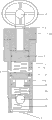
Fig. 1 is the structural representation that is used for the energy-saving pressure-reduction valve embodiment 1 of hydraulic system of the present utility model.
Fig. 2 is the structural representation that is used for the energy-saving pressure-reduction valve embodiment 2 of hydraulic system of the present utility model.
Fig. 3 is the structural representation that is used for the energy-saving pressure-reduction valve embodiment 3 of hydraulic system of the present utility model.
Shown in the figure: 1, valve body, 2, main valve plug, 3, regulating piston, 4, adjusting screw rod, 5, first spring, 6, liquid entering hole, 7, liquid outlet, 8, cavity, 9, second spring, 10, nonreturn valve core, 11, handwheel, 12, back-up ring, 13, leakage opening, 14 and cap, 15, main passage, the 16, the 3rd spring.
Embodiment:
The utility model is described in further detail below in conjunction with the drawings and specific embodiments:
Be provided with the valve core channel that can communicate in the described main valve plug 2 with liquid entering hole 6 and liquid outlet 7, described valve core channel comprises the cavity 8 between main valve plug 2 and valve body 1 inwall at least, and the surface of contact that described cavity 8 is main valve plug 2 and valve body 1 inwall inwardly has breach and forms.
Described liquid entering hole 6 is meant the annular pass that is arranged on the valve body 1, and described annular pass can communicate with cavity 8, and described liquid outlet 7 is provided with one-way valve, and described one-way valve comprises second spring 9 and nonreturn valve core 10.
Described adjusting screw rod 4 is provided with handwheel 11, adjusting screw rod 4 is screwed in or the back-out valve body by handwheel 11 rotations, thereby regulates the pressure of first spring 5.
Described main valve plug 2 upper ends connect first spring 5, and the back-up ring of being located on the valve body 12 is withstood in the lower end, thereby main valve plug is blocked, and is spacing to main valve plug; Also have leakage opening 13 on the described valve body, described leakage opening 13 is when moving on the main valve plug, escapes and enter in the liquid tank pressing on the partially liq in the valve body.
Claims (4)
1. energy-saving pressure-reduction valve that is used for hydraulic system, comprise valve body (1), main valve plug (2), regulating piston (3) and adjusting screw rod (4), described main valve plug (2) and regulating piston (3) all are loaded in the valve body (1), described main valve plug (2) is connected on the regulating piston (3) through first spring (5), described main valve plug (2) and valve body (1) inwall Spielpassung; Described adjusting screw rod withstands regulating piston (3); Described valve body (1) is provided with liquid entering hole (6) and liquid outlet (7), liquid entering hole (6) locates to be high tension loop, liquid outlet (7) locates to be low tension loop, it is characterized in that: be provided with the valve core channel that can communicate in the described main valve plug (2) with liquid entering hole (6) and liquid outlet (7), described valve core channel comprises the cavity (8) between main valve plug (2) and valve body (1) inwall at least, and described cavity (8) is that the surface of contact of main valve plug (2) and valve body (1) inwall inwardly has breach formation.
2. the energy-saving pressure-reduction valve that is used for hydraulic system according to claim 1 is characterized in that: described valve core channel also comprises the main passage (15) that all communicates with cavity (8) and liquid entering hole (6), and described main passage (15) are provided with in the valve core channel.
3. the energy-saving pressure-reduction valve that is used for hydraulic system according to claim 1, it is characterized in that: described valve body also is provided with one-way valve in (1), described one-way valve is located at liquid entering hole (6) or liquid outlet (7) is located, and one-way valve comprises second spring (9) and nonreturn valve core (10).
4. according to claim 2 or the 3 described energy-saving pressure-reduction valves that are used for hydraulic system, it is characterized in that: described one-way valve can also be located in the main valve plug (2), described second spring (9) one ends are fixed on the inner end face of main valve plug (2), the other end is connected with nonreturn valve core (10), and described nonreturn valve core (10) withstands the main passage mouth.
Priority Applications (1)
| Application Number | Priority Date | Filing Date | Title |
|---|---|---|---|
| CN2011200368195U CN201934411U (en) | 2011-01-30 | 2011-01-30 | Energy-saving pressure relief valve of hydraulic system |
Applications Claiming Priority (1)
| Application Number | Priority Date | Filing Date | Title |
|---|---|---|---|
| CN2011200368195U CN201934411U (en) | 2011-01-30 | 2011-01-30 | Energy-saving pressure relief valve of hydraulic system |
Publications (1)
| Publication Number | Publication Date |
|---|---|
| CN201934411U true CN201934411U (en) | 2011-08-17 |
Family
ID=44445930
Family Applications (1)
| Application Number | Title | Priority Date | Filing Date |
|---|---|---|---|
| CN2011200368195U Expired - Fee Related CN201934411U (en) | 2011-01-30 | 2011-01-30 | Energy-saving pressure relief valve of hydraulic system |
Country Status (1)
| Country | Link |
|---|---|
| CN (1) | CN201934411U (en) |
Cited By (2)
| Publication number | Priority date | Publication date | Assignee | Title |
|---|---|---|---|---|
| CN102072216A (en) * | 2011-01-30 | 2011-05-25 | 林友根 | Energy-saving reducing valve for hydraulic system |
| CN113002783A (en) * | 2021-04-08 | 2021-06-22 | 安徽砺德特种动力科技有限公司 | Electric control type pump body, driving device for unmanned aerial vehicle and fluid transmission method |
-
2011
- 2011-01-30 CN CN2011200368195U patent/CN201934411U/en not_active Expired - Fee Related
Cited By (3)
| Publication number | Priority date | Publication date | Assignee | Title |
|---|---|---|---|---|
| CN102072216A (en) * | 2011-01-30 | 2011-05-25 | 林友根 | Energy-saving reducing valve for hydraulic system |
| CN102072216B (en) * | 2011-01-30 | 2014-12-17 | 林友根 | Energy-saving reducing valve for hydraulic system |
| CN113002783A (en) * | 2021-04-08 | 2021-06-22 | 安徽砺德特种动力科技有限公司 | Electric control type pump body, driving device for unmanned aerial vehicle and fluid transmission method |
Similar Documents
| Publication | Publication Date | Title |
|---|---|---|
| CN203223431U (en) | Threaded plug-in type three-way reducing valve | |
| CN201963624U (en) | Pressure regulating valve to control oil pressure | |
| CN203363266U (en) | Internal thread type ball valve with draining device | |
| CN102425520A (en) | Embedded oil charging structure for high-pressure fuel oil system | |
| CN102072216A (en) | Energy-saving reducing valve for hydraulic system | |
| CN103291986A (en) | Directly-operated type reducing valve | |
| CN204677346U (en) | Normally closed electromechanical compound high pressure oil pump | |
| CN202531513U (en) | Back pressure valve for hydraulic oil return system | |
| CN203718031U (en) | Button valve | |
| CN104806406B (en) | Normally closed electromechanical composite high-pressure oil pump | |
| CN202832603U (en) | A New Kind of Medium Flow Hydraulic Control Check Valve | |
| CN203892648U (en) | Differential safety valve and oil inlet connecting plate assembly with same | |
| CN203718065U (en) | Pressure release valve | |
| CN203214992U (en) | Simple pressure reducing valve | |
| CN217632894U (en) | Mining emulsion plunger pump | |
| CN201057068Y (en) | Oil pump pressure regulator | |
| CN201269187Y (en) | Pressure-regulating spilling system of plunger type high-pressure water pump | |
| CN206233967U (en) | Engine oil pump with decompression function | |
| CN2665480Y (en) | Proportional pressure-reducing valve | |
| CN2516778Y (en) | Multifunction water pump control valve | |
| CN205908811U (en) | Flange formula hydraulic check valve | |
| CN202176565U (en) | Flow amplifying valve | |
| CN204985175U (en) | Take hydraulic transmission device of flushometer | |
| CN204200566U (en) | A kind of safety valve of hydraulic planger pump | |
| CN202250115U (en) | Plug-in type hard sealing bidirectional lock |
Legal Events
| Date | Code | Title | Description |
|---|---|---|---|
| C14 | Grant of patent or utility model | ||
| GR01 | Patent grant | ||
| CF01 | Termination of patent right due to non-payment of annual fee |
Granted publication date: 20110817 Termination date: 20150130 |
|
| EXPY | Termination of patent right or utility model |