CN201933965U - Door with automatic control lamp - Google Patents
Door with automatic control lamp Download PDFInfo
- Publication number
- CN201933965U CN201933965U CN2010206521048U CN201020652104U CN201933965U CN 201933965 U CN201933965 U CN 201933965U CN 2010206521048 U CN2010206521048 U CN 2010206521048U CN 201020652104 U CN201020652104 U CN 201020652104U CN 201933965 U CN201933965 U CN 201933965U
- Authority
- CN
- China
- Prior art keywords
- door
- automatic control
- power supply
- leaf
- spring leaf
- Prior art date
- Legal status (The legal status is an assumption and is not a legal conclusion. Google has not performed a legal analysis and makes no representation as to the accuracy of the status listed.)
- Expired - Fee Related
Links
Images


Classifications
-
- Y—GENERAL TAGGING OF NEW TECHNOLOGICAL DEVELOPMENTS; GENERAL TAGGING OF CROSS-SECTIONAL TECHNOLOGIES SPANNING OVER SEVERAL SECTIONS OF THE IPC; TECHNICAL SUBJECTS COVERED BY FORMER USPC CROSS-REFERENCE ART COLLECTIONS [XRACs] AND DIGESTS
- Y02—TECHNOLOGIES OR APPLICATIONS FOR MITIGATION OR ADAPTATION AGAINST CLIMATE CHANGE
- Y02B—CLIMATE CHANGE MITIGATION TECHNOLOGIES RELATED TO BUILDINGS, e.g. HOUSING, HOUSE APPLIANCES OR RELATED END-USER APPLICATIONS
- Y02B20/00—Energy efficient lighting technologies, e.g. halogen lamps or gas discharge lamps
- Y02B20/40—Control techniques providing energy savings, e.g. smart controller or presence detection
Landscapes
- Arrangement Of Elements, Cooling, Sealing, Or The Like Of Lighting Devices (AREA)
Abstract
一种带自控灯的门,包括门框和门扇,在门框上部内侧设有灯泡,门框门锁侧内部设有自控装置,自控装置通过导线与灯泡连接,所述自控装置包括电源和弹簧片,电源和弹簧片之间连接有导线,门扇门锁侧相对于自控装置的地方设有永磁铁。本实用新型结构简单,加工方便,新颖独特。尤其适合晚上使用,再打开门的一瞬间会发生光亮,给人一种惊喜和愉悦。
A door with an automatic control lamp, including a door frame and a door leaf, a light bulb is arranged on the inner side of the upper part of the door frame, and an automatic control device is arranged inside the door lock side of the door frame. The automatic control device is connected to the light bulb through a wire. A wire is connected with the spring leaf, and a permanent magnet is arranged on the door lock side of the door leaf relative to the automatic control device. The utility model has the advantages of simple structure, convenient processing, novelty and uniqueness. It is especially suitable for use at night, and the moment the door is opened, it will be illuminated, giving people a kind of surprise and joy.
Description
技术领域technical field
本实用新型属于日常生活领域,尤其涉及一种带自控灯的门。The utility model belongs to the field of daily life, in particular to a door with an automatic control lamp.
背景技术Background technique
随着人们生活水平的不断提高,大家在外工作了一天,家就是逼疯的港湾,回到家人们就需要休息,所以在家里装一扇人性化的门,能给我们带来不少方便。现在家里的门比较普通,大多为木门、铁门和复合门,下班回家往往已经是晚上,楼道内有路灯还好,没有的话就得抹黑前行,打开家门仍是一片漆黑,实属不便。With the continuous improvement of people's living standards, everyone works outside for a day, and the home is a haven for madness. When they return home, they need to rest. Therefore, installing a humanized door at home can bring us a lot of convenience. Now the doors at home are relatively common, mostly wooden doors, iron doors and composite doors. It is often late at night when you come home from work. It is good to have street lights in the corridor. .
实用新型内容Utility model content
本实用新型所要解决的技术问题是提供一种在开门时能自动开启灯光的门。The technical problem to be solved by the utility model is to provide a door that can automatically turn on the light when the door is opened.
为了解决上述技术问题采用以下技术方案:一种带自控灯的门,包括门框和门扇,在门框上部内侧设有灯泡,门框门锁侧内部设有自控装置,自控装置通过导线与灯泡连接,所述自控装置包括电源和弹簧片,电源和弹簧片之间连接有导线,门扇门锁侧相对于自控装置的地方设有永磁铁。In order to solve the above technical problems, the following technical solutions are adopted: a door with an automatic control lamp, including a door frame and a door leaf, a light bulb is arranged on the inner side of the upper part of the door frame, and an automatic control device is arranged inside the door lock side of the door frame, and the automatic control device is connected to the light bulb through a wire. The automatic control device includes a power supply and a spring leaf, a wire is connected between the power supply and the spring leaf, and a permanent magnet is arranged on the door lock side of the door leaf relative to the automatic control device.
弹簧片一端通过导线连接在电源一极,电源另一极连接接触点,在关门状态下,弹簧片处于常开状态。One end of the spring piece is connected to one pole of the power supply through a wire, and the other pole of the power supply is connected to the contact point. When the door is closed, the spring piece is in a normally open state.
所述的灯泡为LED灯。The bulb is an LED lamp.
所述的电源为干电池组。The power supply is a dry battery pack.
本实用新型结构简单,加工方便,新颖独特。尤其适合晚上使用,再打开门的一瞬间会发生光亮,给人一种惊喜和愉悦。The utility model has the advantages of simple structure, convenient processing, novelty and uniqueness. It is especially suitable for use at night, and the moment the door is opened, it will be illuminated, giving people a kind of surprise and joy.
附图说明Description of drawings
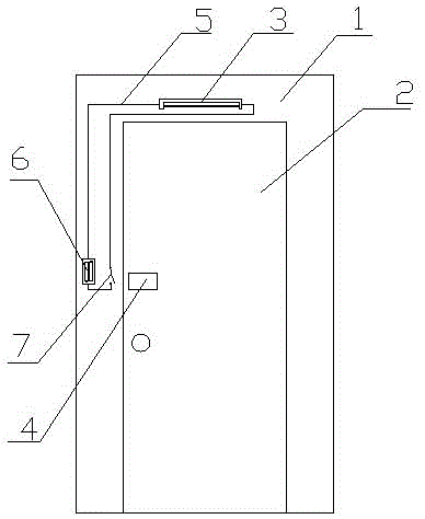
图1为本实用新型的结构示意图。Fig. 1 is the structural representation of the utility model.
图2为本实用新型的使用状态图。Fig. 2 is the use status diagram of the utility model.
具体实施方式Detailed ways
如图1、2所示,:一种带自控灯的门,包括门框1和门扇2,在门框1上部内侧设有一盏LED灯3,门框1门锁侧内部设有自控装置,自控装置通过导线5与LED灯3连接,所述自控装置包括干电池组6电源和弹簧片7,干电池组6和弹簧片7之间连接有导线,门扇2门锁侧相对于自控装置的地方设有永磁铁4。弹簧片一端通过导线连接在电源一极,干电池组另一极连接接触点。As shown in Figures 1 and 2, a door with an automatic control light includes a
在关门状态下,弹簧片收到磁铁的吸引离开接触点,处于常开状态;在开门后,磁铁的磁性不足以吸引弹簧片,弹簧片靠自身的弹性连接在接触点上,接通电路,LED亮起。In the state of closing the door, the spring piece is attracted by the magnet and leaves the contact point, and is in the normally open state; after the door is opened, the magnetic force of the magnet is not enough to attract the spring piece, and the spring piece is connected to the contact point by its own elasticity, and the circuit is connected. The LED lights up.
Claims (4)
- One kind with automatic controlling lamp the door, comprise doorframe and door leaf, it is characterized in that: be provided with bulb in the doorframe upper inner, doorframe door lock side inside is provided with self-con-tained unit, self-con-tained unit is connected with bulb by lead, described self-con-tained unit comprises power supply and spring leaf, is connected with lead between power supply and the spring leaf, and door leaf door lock side is provided with permanent magnet with respect to the place of self-con-tained unit.
- 2. the door of band automatic controlling lamp according to claim 1 is characterized in that: spring leaf one end is connected power supply one utmost point by lead, and another utmost point of power supply connects contact point, and under the state of closing the door, spring leaf is in normally open.
- 3. the door of band automatic controlling lamp according to claim 1 is characterized in that: described bulb is the LED lamp.
- 4. the door of band automatic controlling lamp according to claim 1 is characterized in that: described power supply is a dry cell batteries.
Priority Applications (1)
| Application Number | Priority Date | Filing Date | Title |
|---|---|---|---|
| CN2010206521048U CN201933965U (en) | 2010-12-10 | 2010-12-10 | Door with automatic control lamp |
Applications Claiming Priority (1)
| Application Number | Priority Date | Filing Date | Title |
|---|---|---|---|
| CN2010206521048U CN201933965U (en) | 2010-12-10 | 2010-12-10 | Door with automatic control lamp |
Publications (1)
| Publication Number | Publication Date |
|---|---|
| CN201933965U true CN201933965U (en) | 2011-08-17 |
Family
ID=44445487
Family Applications (1)
| Application Number | Title | Priority Date | Filing Date |
|---|---|---|---|
| CN2010206521048U Expired - Fee Related CN201933965U (en) | 2010-12-10 | 2010-12-10 | Door with automatic control lamp |
Country Status (1)
| Country | Link |
|---|---|
| CN (1) | CN201933965U (en) |
-
2010
- 2010-12-10 CN CN2010206521048U patent/CN201933965U/en not_active Expired - Fee Related
Similar Documents
| Publication | Publication Date | Title |
|---|---|---|
| CN205189605U (en) | Magnetic force actuation smart door and window control system | |
| CN203671387U (en) | Gating indoor lighting device | |
| CN201007461Y (en) | door control light | |
| CN201937881U (en) | Toilet energy-saving lighting device | |
| CN203285145U (en) | Door provided with automatic lamp | |
| CN203136297U (en) | A corridor lamp control system | |
| CN205546060U (en) | Two induction type LED wall lamps | |
| CN201602458U (en) | magnetic mosquito net | |
| CN201246710Y (en) | Household gate control lamp | |
| CN202444668U (en) | LED switch controller | |
| CN202544508U (en) | Intelligent luminous door handle | |
| CN204463270U (en) | A kind of Porta Potti Intelligent door lock control system | |
| CN202284408U (en) | Emergency door handle | |
| CN203129738U (en) | Light prompting lock for deaf-mutes | |
| CN104680635A (en) | Intelligent door lock control system for mobile toilet | |
| CN202561523U (en) | Intelligent light-emitting diode (LED) light | |
| CN201687375U (en) | Door-closing reminder | |
| CN201753559U (en) | Remote-controlled window | |
| CN202775760U (en) | Curtain with magnetic closure device | |
| CN202191154U (en) | Electric curtain | |
| CN202328079U (en) | Wardrobe light controller | |
| CN202380908U (en) | Magnetic automatic door | |
| CN203347408U (en) | Window opening device | |
| CN202164870U (en) | Novel doorknob | |
| CN201406960Y (en) | Door with control light switch |
Legal Events
| Date | Code | Title | Description |
|---|---|---|---|
| C14 | Grant of patent or utility model | ||
| GR01 | Patent grant | ||
| C17 | Cessation of patent right | ||
| CF01 | Termination of patent right due to non-payment of annual fee |
Granted publication date: 20110817 Termination date: 20111210 |