CN201895103U - Special-purpose machine tool for boring front frames - Google Patents
Special-purpose machine tool for boring front frames Download PDFInfo
- Publication number
- CN201895103U CN201895103U CN201020598791XU CN201020598791U CN201895103U CN 201895103 U CN201895103 U CN 201895103U CN 201020598791X U CN201020598791X U CN 201020598791XU CN 201020598791 U CN201020598791 U CN 201020598791U CN 201895103 U CN201895103 U CN 201895103U
- Authority
- CN
- China
- Prior art keywords
- lengthening
- base
- lengthened
- shaft boring
- machine tool
- Prior art date
- Legal status (The legal status is an assumption and is not a legal conclusion. Google has not performed a legal analysis and makes no representation as to the accuracy of the status listed.)
- Expired - Fee Related
Links
Images
Abstract
The utility model aims to provide a special-purpose machine tool applicable to realizing double-surface boring for front frames. The special-purpose machine tool consists of a side base, a lengthened side base, a mechanical slide table, a lengthened mechanical slide table, two double-shaft boring heads, two transmissions, two adjusting pads, a fixture and a middle base. Two sides of the middle base are respectively connected with the side base and the lengthened side base, the fixture is disposed at the upper end of the middle base, the side base is provided with one adjusting pad, the mechanical slide table is disposed on the adjusting pad and provided with one double-shaft boring head provided with one transmission at the rear end, the other adjusting pad is arranged on the lengthened side base and provided with the lengthened mechanical slide table, the other double-shaft boring head is disposed on the lengthened mechanical slide table, and the other transmission is arranged at the rear end of the other double-shaft boring head. The lengthened side base and the lengthened slide table bring more convenience for defining a processing range of workpieces. Besides, the special-purpose machine tool is higher in processing efficiency and brings more convenience for operation of operators.
Description
Technical field
The utility model relates to machine tool field, concretely, relates to a kind of front frame bore hole special purpose machine tool.
Background technology
Lathe is the lathe that mainly with lathe tool the workpiece of rotation is carried out turning processing.Also available drill bit, reamer, reamer, screw tap, screw die and checkering tool etc. are processed accordingly on lathe.Lathe is mainly used in and processes axle, dish, overlaps and other have the workpiece of rotary surface, is to use a widest class lathe in machine-building and the repair factory.
Summary of the invention
The purpose of this utility model provides a kind of two-sided bore hole Special Purpose Machine for Processing that is applicable to front frame.
The utility model is made of a wing base, a lengthening wing base, a mechanical skid plateform, a lengthening mechanical skid plateform, two twin shaft boring heads, two transmission devices, two adjusting pads, anchor clamps, a center base; The center base both sides connect wing base and lengthening wing base respectively, there are anchor clamps the center base upper end, adjusting pad is arranged on the wing base, mechanical skid plateform is arranged on the adjusting pad, the twin shaft boring head is arranged on the mechanical skid plateform, there is transmission device twin shaft boring head rear end, on the lengthening wing base adjusting pad is arranged, the lengthening mechanical skid plateform is arranged on the adjusting pad, on the lengthening mechanical skid plateform twin shaft boring head is arranged, there is transmission device twin shaft boring head rear end.
On the described mechanical skid plateform protector is arranged.
Advantage of the present utility model is: the be more convenient for range of work of workpiece of lengthening wing base and lengthening slide unit, working (machining) efficiency is higher, the operator's that is more convenient for operation.
Description of drawings
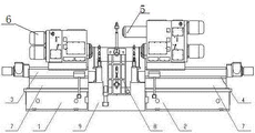
Fig. 1 is the utility model structural representation.
The specific embodiment
Reference numeral shown in Figure 1 is as follows: wing base 1, lengthening wing base 2, mechanical skid plateform 3, lengthening mechanical skid plateform 4, twin shaft boring head 5, transmission device 6, adjusting pad 7, anchor clamps 8, a center base 9.
The utility model is made of a wing base 1, lengthening wing base 2, mechanical skid plateform 3, lengthening mechanical skid plateform 4, two twin shaft boring heads 5, two transmission devices 6, two adjusting pads 7, anchor clamps 8, a center base 9; Center base 9 both sides connect wing base 1 and lengthening wing base 2 respectively, there are anchor clamps 8 center base 9 upper ends, adjusting pad 7 is arranged on the wing base 1, mechanical skid plateform 3 is arranged on the adjusting pad 7, twin shaft boring head 5 is arranged on the mechanical skid plateform 3, there is transmission device 6 twin shaft boring head 5 rear ends, on the lengthening wing base 2 adjusting pad 7 is arranged, lengthening mechanical skid plateform 4 is arranged on the adjusting pad 7, on the lengthening mechanical skid plateform 4 twin shaft boring head 5 is arranged, there is transmission device 6 twin shaft boring head 5 rear ends.
On described mechanical skid plateform 3 and the lengthening mechanical skid plateform 4 protector is arranged.
Claims (2)
1. front frame bore hole special purpose machine tool is characterized in that: be made of a wing base, lengthening wing base, mechanical skid plateform, lengthening mechanical skid plateform, two twin shaft boring heads, two transmission devices, two adjusting pads, anchor clamps, center base; The center base both sides connect wing base and lengthening wing base respectively, there are anchor clamps the center base upper end, adjusting pad is arranged on the wing base, mechanical skid plateform is arranged on the adjusting pad, the twin shaft boring head is arranged on the mechanical skid plateform, there is transmission device twin shaft boring head rear end, on the lengthening wing base adjusting pad is arranged, the lengthening mechanical skid plateform is arranged on the adjusting pad, on the lengthening mechanical skid plateform twin shaft boring head is arranged, there is transmission device twin shaft boring head rear end.
2. front frame bore hole special purpose machine tool according to claim 1 is characterized in that: on the described mechanical skid plateform protector is arranged.
Priority Applications (1)
| Application Number | Priority Date | Filing Date | Title |
|---|---|---|---|
| CN201020598791XU CN201895103U (en) | 2010-11-10 | 2010-11-10 | Special-purpose machine tool for boring front frames |
Applications Claiming Priority (1)
| Application Number | Priority Date | Filing Date | Title |
|---|---|---|---|
| CN201020598791XU CN201895103U (en) | 2010-11-10 | 2010-11-10 | Special-purpose machine tool for boring front frames |
Publications (1)
| Publication Number | Publication Date |
|---|---|
| CN201895103U true CN201895103U (en) | 2011-07-13 |
Family
ID=44253022
Family Applications (1)
| Application Number | Title | Priority Date | Filing Date |
|---|---|---|---|
| CN201020598791XU Expired - Fee Related CN201895103U (en) | 2010-11-10 | 2010-11-10 | Special-purpose machine tool for boring front frames |
Country Status (1)
| Country | Link |
|---|---|
| CN (1) | CN201895103U (en) |
Cited By (3)
| Publication number | Priority date | Publication date | Assignee | Title |
|---|---|---|---|---|
| CN102744436A (en) * | 2012-07-05 | 2012-10-24 | 王庆 | Device for boring shaft hole of STR air chamber bracket cam |
| CN103286341A (en) * | 2013-06-01 | 2013-09-11 | 苏佳和 | Special double-spindle numerical-control boring machine |
| CN105195776A (en) * | 2015-09-22 | 2015-12-30 | 宁波豪顺科创机械制造有限公司 | Double-face boring tool |
-
2010
- 2010-11-10 CN CN201020598791XU patent/CN201895103U/en not_active Expired - Fee Related
Cited By (5)
| Publication number | Priority date | Publication date | Assignee | Title |
|---|---|---|---|---|
| CN102744436A (en) * | 2012-07-05 | 2012-10-24 | 王庆 | Device for boring shaft hole of STR air chamber bracket cam |
| CN103286341A (en) * | 2013-06-01 | 2013-09-11 | 苏佳和 | Special double-spindle numerical-control boring machine |
| CN103286341B (en) * | 2013-06-01 | 2016-08-24 | 苏佳和 | Double-spindle numerical control Special machine for boring |
| CN105195776A (en) * | 2015-09-22 | 2015-12-30 | 宁波豪顺科创机械制造有限公司 | Double-face boring tool |
| CN105195776B (en) * | 2015-09-22 | 2018-03-13 | 宁波豪顺科创机械制造有限公司 | A kind of double-faced boring frock |
Similar Documents
| Publication | Publication Date | Title |
|---|---|---|
| CN201076938Y (en) | Special machine tool for milling end-face and drilling centre bore | |
| CN102528503A (en) | Double-sided drilling fixture | |
| CN203765039U (en) | Gearbox operation body drilling and reaming jig | |
| ATE459451T1 (en) | SPINDLE UNIT WITH WORK SPINDLE THAT CAN BE ADJUSTABLE DURING OPERATION | |
| CN208528132U (en) | A kind of axial workpiece drill centres machine tool | |
| CN201895103U (en) | Special-purpose machine tool for boring front frames | |
| CN207629680U (en) | A kind of bearing fixture for drilling | |
| CN102990386A (en) | Drilling device | |
| CN206373626U (en) | A kind of fixture for vertical hole drill machine | |
| CN102814507A (en) | Turning end face chamfering machine tool | |
| CN203579252U (en) | T-shaped part stepped end face milling and clamping device | |
| CN202592124U (en) | Rapid index head | |
| CN202356674U (en) | Deep hole drilling jig | |
| CN205271531U (en) | A multistation numerical control anchor clamps for processing of case casing | |
| CN204504278U (en) | A kind of single head numerical control drilling machine | |
| CN210132285U (en) | Device for rapidly clamping workpiece | |
| CN201313261Y (en) | Special clamp for wire-cutter milling groove | |
| CN206286589U (en) | A kind of Horizontal double-headed machine special for drilling | |
| CN202763052U (en) | Face work chamfering lathe | |
| CN203830770U (en) | Drilling tool for switch shell | |
| CN202804640U (en) | Vertical type boring and honing complex machine tool | |
| CN201768933U (en) | Six-axis boring machine tool | |
| CN206997870U (en) | Combination type milling cutter structure is used in a kind of small labyrinth face machining | |
| CN201895101U (en) | Horizontal double-surface and double-station drill and ream combined machine tool | |
| CN204657551U (en) | Thin-wall bush class part bores the frock of multiple eccentric orfice |
Legal Events
| Date | Code | Title | Description |
|---|---|---|---|
| C14 | Grant of patent or utility model | ||
| GR01 | Patent grant | ||
| C17 | Cessation of patent right | ||
| CF01 | Termination of patent right due to non-payment of annual fee |
Granted publication date: 20110713 Termination date: 20121110 |