CN201842751U - Sludge solidification treatment machine - Google Patents
Sludge solidification treatment machine Download PDFInfo
- Publication number
- CN201842751U CN201842751U CN2010206100284U CN201020610028U CN201842751U CN 201842751 U CN201842751 U CN 201842751U CN 2010206100284 U CN2010206100284 U CN 2010206100284U CN 201020610028 U CN201020610028 U CN 201020610028U CN 201842751 U CN201842751 U CN 201842751U
- Authority
- CN
- China
- Prior art keywords
- solidifying agent
- sludge
- mud
- sludge solidification
- handler
- Prior art date
- Legal status (The legal status is an assumption and is not a legal conclusion. Google has not performed a legal analysis and makes no representation as to the accuracy of the status listed.)
- Expired - Lifetime
Links
- 239000010802 sludge Substances 0.000 title claims abstract description 40
- 238000007711 solidification Methods 0.000 title claims abstract description 29
- 230000008023 solidification Effects 0.000 title claims abstract description 29
- 239000003795 chemical substances by application Substances 0.000 claims abstract description 41
- 238000003756 stirring Methods 0.000 claims abstract description 38
- 230000007306 turnover Effects 0.000 claims description 13
- 239000004744 fabric Substances 0.000 claims description 11
- 238000005303 weighing Methods 0.000 claims description 7
- 230000006378 damage Effects 0.000 abstract description 4
- 239000012535 impurity Substances 0.000 abstract description 4
- 230000007246 mechanism Effects 0.000 abstract description 4
- 239000007787 solid Substances 0.000 abstract description 4
- 238000001914 filtration Methods 0.000 abstract description 3
- XLYOFNOQVPJJNP-UHFFFAOYSA-N water Substances O XLYOFNOQVPJJNP-UHFFFAOYSA-N 0.000 description 8
- 238000000034 method Methods 0.000 description 6
- 230000008569 process Effects 0.000 description 4
- 238000012546 transfer Methods 0.000 description 4
- 230000007613 environmental effect Effects 0.000 description 3
- 238000004519 manufacturing process Methods 0.000 description 3
- 239000000463 material Substances 0.000 description 3
- IJGRMHOSHXDMSA-UHFFFAOYSA-N Atomic nitrogen Chemical compound N#N IJGRMHOSHXDMSA-UHFFFAOYSA-N 0.000 description 2
- 238000009825 accumulation Methods 0.000 description 2
- 230000008859 change Effects 0.000 description 2
- 238000010276 construction Methods 0.000 description 2
- 238000005265 energy consumption Methods 0.000 description 2
- 230000008676 import Effects 0.000 description 2
- 239000002689 soil Substances 0.000 description 2
- 239000002699 waste material Substances 0.000 description 2
- 102000002322 Egg Proteins Human genes 0.000 description 1
- 108010000912 Egg Proteins Proteins 0.000 description 1
- OAICVXFJPJFONN-UHFFFAOYSA-N Phosphorus Chemical compound [P] OAICVXFJPJFONN-UHFFFAOYSA-N 0.000 description 1
- 244000052616 bacterial pathogen Species 0.000 description 1
- 230000002950 deficient Effects 0.000 description 1
- 238000013461 design Methods 0.000 description 1
- 238000010586 diagram Methods 0.000 description 1
- 238000005516 engineering process Methods 0.000 description 1
- 235000021050 feed intake Nutrition 0.000 description 1
- 238000005189 flocculation Methods 0.000 description 1
- 230000016615 flocculation Effects 0.000 description 1
- 229910001385 heavy metal Inorganic materials 0.000 description 1
- 239000010814 metallic waste Substances 0.000 description 1
- 230000004048 modification Effects 0.000 description 1
- 238000012986 modification Methods 0.000 description 1
- 229910052757 nitrogen Inorganic materials 0.000 description 1
- 230000000050 nutritive effect Effects 0.000 description 1
- 210000004681 ovum Anatomy 0.000 description 1
- 244000045947 parasite Species 0.000 description 1
- 229910052698 phosphorus Inorganic materials 0.000 description 1
- 239000011574 phosphorus Substances 0.000 description 1
- 231100000614 poison Toxicity 0.000 description 1
- 230000007096 poisonous effect Effects 0.000 description 1
- 238000012797 qualification Methods 0.000 description 1
- 239000010865 sewage Substances 0.000 description 1
- 239000004575 stone Substances 0.000 description 1
- 239000000126 substance Substances 0.000 description 1
Images



Landscapes
- Treatment Of Sludge (AREA)
Abstract
The utility model relates to a sludge solidification treatment machine. A stirring bin is arranged on the lower portion of a frame, two helical stirring shafts rotating relatively are arranged inside the stirring bin and driven to rotate by a main motor, two feed inlets are arranged above an initial section of the stirring bin, one of the feed inlets is a sludge feed inlet which is in series connection with a sludge conveying belt, a sludge hopper and a sludge conveying screw shaft so as to convey sludge, the other feed inlet is a solidifying agent feed inlet which is in series connection with a solidifying agent conveying belt, a solidifying agent hopper and a solidifying agent conveying screw shaft, and a tail-end discharge outlet of the stirring bin is arranged above a sludge solidifying tank. The sludge solidification treatment machine is compact and reasonable in structure, small in floor area, and modifies a large-size structure needing a lifting mechanism to convey solidifying agent in the prior art. Furthermore, a flap filtering device arranged at an inlet of the sludge hopper can filter large solid impurities in sludge in time effectively, thereby preventing blockage and damages of equipment and reducing failure rate.
Description
Technical field
The utility model relates to a kind of sludge treatment equipment, especially a kind of sludge solidification handler.
Background technology
Lake and bed-silt water content are big, wherein remove to contain a large amount of organism and nutritive substances such as the nitrogen that enriches, phosphorus, also have heavy metal, pathogenic bacterium and parasite poisonous and harmful elements such as (ovum); If mud is unprocessed or deal with improperly, very easily bring serious secondary pollution and environmental destruction, contaminated soil, water source even food chain, so mud is disposed and is seemed and be even more important.The process for treating sludge of existing a kind of main flow is by mix solidifying agent in the mud of high-moisture, in the sludge solidification pond through after a while flocculation and precipitin reaction, final curing is the few dense thick mud of water content, this mud can carry out landfill or be converted into the farmland or soil for building, and final realization is turned waste into wealth, the environmental protection purpose of recycle.Chinese patent 200420028026.9---" sludge solidification handler " discloses a kind of waste silt that rivers and lakes and waterworks, sewage work, construction site etc. are located and has solidified the sludge solidification handler that utilizes again, comprise frame, whipping appts is arranged on the frame; Two of whipping appts has import and outlet respectively, and there is the curing feed bin its top; Solidifying feed bin and mud feed bin bottom all has feed opening, this feed opening to be in directly over the import of whipping appts; Frame one side has into mud transfer roller, and this advances mud transfer roller one end and is higher than its other end, itself and the high-end mud feed bin top of being in.There is following defective in this sludge solidification handler: (one) is provided with lifting mechanism at the curing feed bin, need solidify material be sent into by lifting mechanism during work and solidify in the feed bin, and not only floor space is big, and production efficiency is low, and energy consumption height, cost are also high; (2) owing to contain the bigger solid impurity of more volume for example masonry piece, metal waste residue etc. in the mud,, then can result in blockage or shut down, when serious even damage equipment if enter agitator; (3) this equipment need fix on the ground, can't move easily, limits its range of application; (4) agitator design is the screw-blade of single direction, and mud easily in local accumulation, is produced the dead angle by unidirectional conveying in the helical feed process, influence transport efficiency, when serious even the obstruction transport pipe.
The utility model content
The applicant is big at the floor space of above-mentioned sludge solidification handler of the prior art, low, the shortcomings such as energy consumption is high, poor mobility of work production efficiency, provide that a kind of floor space is little, treatment capacity is big, adaptable sludge solidification handler, thereby improve work production efficiency, be convenient to move.
The technical scheme that the utility model adopted is as follows:
A kind of sludge solidification handler, bottom in frame is provided with stir storehouse, stir storehouse inside is provided with two counterrotating helical stir axles, stir shaft is rotated by main electric motor driving, above the stir storehouse initial section, be provided with the two-way opening for feed, one tunnel mud opening for feed for the conveying of connecting with mud conveyor screw axle by mud conveying belt, mud hopper, the solidifying agent opening for feed of another road for connecting and carry by solidifying agent conveying belt, solidifying agent hopper, solidifying agent conveyor screw axle; The terminal discharge port of stir storehouse is arranged on the top in sludge solidification pond.It is further characterized in that:
In the ingress of described mud hopper the screen cloth turnover panel is set, described screen cloth turnover panel one side articulates with turning axle and frame, and opposite side is connected by the elevator dish of pull wire with the lifting motor output shaft that is fixed on frame.
Described solidifying agent conveying belt is provided with Weighing device, and described Weighing device adopts the electronic scales of flow sensing, and its output terminal connects the electric machine controller of described solidifying agent conveying belt.
Described helical stir axle middle part is provided with backward vane, and its spiral angle and other agitating vanes oppositely are provided with.
Described backward vane is provided with one group or two groups.
Be provided with flat base in described frame bottom, its edge is the inclined-plane of perk.
Be provided with ship type base in described frame bottom, its inside is provided with buoyancy compartment.
The utility model compact construction is reasonable, and floor space is little, and having improved needs lifting mechanism to carry the large scale structure of solidifying agent in the prior art.The utility model is provided with the turnover panel filtration unit in the ingress of mud hopper, can filter the large volume solid impurity of removing in the mud timely and effectively, prevents to stop up and damage equipment, and failure rate is low.The utility model is provided with several to backward vane at helical stir axle middle part, can smash the mud of caking, carries out subsequent delivery smoothly, has avoided the obstruction transport pipe, and working efficiency improves greatly.The utility model solidifying agent conveying belt is provided with Weighing device, can quantitatively feed intake to solidifying agent accurately, has both guaranteed curing efficiency, and avoids contaminate environment, and the feature of environmental protection is good and reduce cost.
The utility model adopts flat base, and the edge perk can be drawn transfer easily on the ground, greatly facilitates it and switches between each sludge solidification pond; The ship type base that the utility model adopts can swim on the water surface in rivers or lake, and the mud after directly will handling drops in the sludge solidification pond of bank base setting, can effectively save the work-yard, carries out equipment flexibly and shifts.
Description of drawings
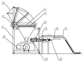
Fig. 1 is a front view of the present utility model.
Fig. 2 is the left view of Fig. 1.
Fig. 3 is a helical stir axle front view of the present utility model.
Fig. 4 looks synoptic diagram for the left side of Fig. 3.
Fig. 5 is the front view of another kind of embodiment of the present utility model.
Embodiment
Below in conjunction with accompanying drawing, embodiment of the present utility model is described.
As shown in Figure 1 and Figure 2, the utility model is provided with stir storehouse 7 in the bottom of frame 6, stir storehouse 7 inside are provided with two counterrotating helical stir axle 8(and see Fig. 3 and Fig. 4), stir shaft 8 drives rotation by main motor 3 by belt pulley 10, above stir storehouse 7 initial section, be provided with the two-way opening for feed, one the tunnel is mud opening for feed 20, and another road is a solidifying agent opening for feed 22.As shown in Figure 1, the bigger mud of water content is delivered to the mud hopper 4 on frame 6 tops by mud conveying belt 1, is provided with mud conveyor screw axle 5 at the bottom of the bucket of mud hopper 4, and it drives by motor 21, is provided with mud opening for feed 20 at the helical feed portion tail end; As shown in Figure 2, solidifying agent is delivered to solidifying agent hopper 15 by solidifying agent conveying belt 17, is delivered to solidifying agent opening for feed 22 by the solidifying agent conveyor screw axle 14 that is driven by motor 23 then.The bottom of frame 6 is provided with flat base 2, and the edge of base 2 is the inclined-plane of perk.During real work, the utility model is placed on 9 edges, sludge solidification pond, and the discharge port 24 of its stir storehouse 7 can directly drop into sludge solidification pond 9 with the mud after stirring.
As shown in Figure 2, quarrel place at mud hopper 4 is provided with the turnover panel filtration unit, screen cloth turnover panel 13 covers the oral area of mud hopper 4, the one side is articulated with turning axle 11 and frame 6, can be to overturn in the center with the axle, the opposite side of screen cloth turnover panel 13 is connected by the elevator dish of pull wire 12 with the lifting motor output shaft that is fixed on frame 6, and the rotating by control lifting motor can make screen cloth turnover panel 13 dig or fall.
During actual job, the mud that water content is bigger is delivered to the mud hopper 4 on frame 6 tops by mud conveying belt 1, and the mud conveyor screw axle 5 that passes through feed hopper bottom falls into stir storehouse 7 through stirring conveying from mud opening for feed 20; Solidifying agent is delivered to solidifying agent hopper 15 by solidifying agent conveying belt 17, and the agent conveyor screw axle 14 that is cured then stirs to be carried, and falls into stir storehouse 7 from solidifying agent opening for feed 22; Mud and solidifying agent are fully mixed by helical stir axle 8 in stir storehouse 7, directly fall into sludge solidification pond 9 from discharge port 24, solidify fully in solidifying pond 9.Usually the desilting place is provided with a plurality of curing pond, after fill in a curing pond, the sludge solidification handler can be transferred to another and solidify next door, pond, and the mud in the previous curing pond promptly can take out from the pond through after the curing of certain hour, is transported to the landfill place or carries out renewable resource utilization.Because flat base 2 edges of the utility model bottom are the inclined-plane of perk, can be drawn transfer easily on the ground.The utility model is provided with screen cloth turnover panel 13 in the ingress of mud hopper 4, screen cloth turnover panel 13 covers at mud hopper 4 oral areas when mud conveying belt 1 feed, can the mud that fall into be filtered, prevent that larger-size solid impurity from falling into hopper and stopping up the subsequent delivery pipeline; At the appointed time back mud conveying belt 1 suspends conveying, and 13 upsets of screen cloth turnover panel are holded up, and top residual stone is poured over a side, and mud conveying belt 1 continues to carry feed after screen cloth turnover panel 13 resets.
The method that prior art is only passed through the rotating speed of control screw conveyor shaft for the charging capacity of solidifying agent realizes, this control method is more coarse, be difficult to solidifying agent is fed intake accurately, and too much or very few input solidifying agent all can influence final sludge solidification result.As shown in Figure 2, solidifying agent conveying belt 17 is provided with Weighing device 16, and Weighing device 16 is the electronic scales of flow sensing principle, by measuring the solidifying agent flow of process, with the rotating speed of feedback signal output control belt conveyor, thereby reach the purpose that accurately feeds intake.
Fig. 3 is the front view of helical stir axle of the present utility model, be provided with spiral angle opposite one group or two groups of backward vane 25-2 at helical stir axle middle part with other agitating vanes 25-1, when agitating vane 25-1 angle is set when spending with vertical plane deflection 10~20, backward vane 25-2 and vertical plane deflection-10~-20 are spent.When actual job, mud and solidifying agent thorough mixing and move under the stirring of agitating vane 25-1 to discharge port 24 directions, may have some in moving process produces caking or produces the dead angle in local accumulation, influence transport efficiency, material was stirred and was smashed through backward vane 25-2 the time this moment, thereby can carry out subsequent delivery smoothly, avoid the obstruction transport pipe; The blade that oppositely is provided with makes mud and solidifying agent change in the local motion direction simultaneously, and the flow state of material changes turbulent flow into by laminar flow, thereby both mix more evenly.
Fig. 5 is an another kind of embodiment of the present utility model, and frame 6 can be directly installed on the ship type base 19, and ship type base 19 inside are provided with buoyancy compartment, can swim on the water surface 18 in rivers or lake.The desilting site of or riverway sludge limited in some places, land, can directly present embodiment be arranged in the water, the desilting boats and ships on next door are directly picked up bed-silt and put into mud hopper 4 with grab bucket, through with the abundant stirring of solidifying agent after, mud directly falls into the sludge solidification pond 9 that the bank is provided with.This structure has not only effectively been saved the work-yard, and conveniently moving, can change the work-yard under the traction of desilting boats and ships fast.
More than describing is to explanation of the present utility model, is not the qualification to utility model, and the utility model institute restricted portion is referring to claim, and under the situation of the utility model spirit, the utility model can be done any type of modification.
Claims (7)
1. sludge solidification handler, bottom in frame is provided with stir storehouse, stir storehouse inside is provided with two counterrotating helical stir axles, stir shaft is rotated by main electric motor driving, it is characterized in that: above the stir storehouse initial section, be provided with the two-way opening for feed, one tunnel mud opening for feed for the conveying of connecting with mud conveyor screw axle by mud conveying belt, mud hopper, the solidifying agent opening for feed of another road for connecting and carry by solidifying agent conveying belt, solidifying agent hopper, solidifying agent conveyor screw axle; The terminal discharge port of stir storehouse is arranged on the top in sludge solidification pond.
2. according to the described sludge solidification handler of claim 1, it is characterized in that: the screen cloth turnover panel is set in the ingress of described mud hopper, described screen cloth turnover panel one side articulates with turning axle and frame, and opposite side is connected by the elevator dish of pull wire with the lifting motor output shaft that is fixed on frame.
3. according to the described sludge solidification handler of claim 1, it is characterized in that: described solidifying agent conveying belt is provided with Weighing device, described Weighing device adopts the electronic scales of flow sensing, and its output terminal connects the electric machine controller of described solidifying agent conveying belt.
4. according to the described sludge solidification handler of claim 1, it is characterized in that: described helical stir axle middle part is provided with backward vane, and its spiral angle and other agitating vanes oppositely are provided with.
5. according to the described sludge solidification handler of claim 4, it is characterized in that: described backward vane is provided with one group or two groups.
6. according to the described sludge solidification handler of claim 1, it is characterized in that: be provided with flat base in described frame bottom, its edge is the inclined-plane of perk.
7. according to the described sludge solidification handler of claim 1, it is characterized in that: be provided with ship type base in described frame bottom, its inside is provided with buoyancy compartment.
Priority Applications (1)
| Application Number | Priority Date | Filing Date | Title |
|---|---|---|---|
| CN2010206100284U CN201842751U (en) | 2010-11-17 | 2010-11-17 | Sludge solidification treatment machine |
Applications Claiming Priority (1)
| Application Number | Priority Date | Filing Date | Title |
|---|---|---|---|
| CN2010206100284U CN201842751U (en) | 2010-11-17 | 2010-11-17 | Sludge solidification treatment machine |
Publications (1)
| Publication Number | Publication Date |
|---|---|
| CN201842751U true CN201842751U (en) | 2011-05-25 |
Family
ID=44037647
Family Applications (1)
| Application Number | Title | Priority Date | Filing Date |
|---|---|---|---|
| CN2010206100284U Expired - Lifetime CN201842751U (en) | 2010-11-17 | 2010-11-17 | Sludge solidification treatment machine |
Country Status (1)
| Country | Link |
|---|---|
| CN (1) | CN201842751U (en) |
Cited By (7)
| Publication number | Priority date | Publication date | Assignee | Title |
|---|---|---|---|---|
| CN102040328A (en) * | 2010-11-17 | 2011-05-04 | 无锡中科建设工程有限公司 | Silt solidification processor |
| CN105672389A (en) * | 2014-10-12 | 2016-06-15 | 童玉兰 | Dredged sediment adding mixing machine for building engineering filling and construction method of machine |
| CN106336099A (en) * | 2016-10-18 | 2017-01-18 | 河海大学 | Charging device of in-situ treatment of polluted bottom sludge |
| CN106430907A (en) * | 2016-10-21 | 2017-02-22 | 江西洁地环境治理生态科技有限公司 | Bottom mud dredging treatment system |
| CN112520959A (en) * | 2020-11-17 | 2021-03-19 | 广东大禹水利建设有限公司 | Waste slurry curing device and waste slurry curing method based on same |
| CN113024057A (en) * | 2021-03-18 | 2021-06-25 | 温州舒谨建筑劳务有限公司 | Construction method for preparing engineering bag by solidifying marine sludge |
| CN117566994A (en) * | 2024-01-15 | 2024-02-20 | 惠州金茂源环保科技有限公司 | Equipment for extracting and recycling heavy metals from electroplating sludge |
-
2010
- 2010-11-17 CN CN2010206100284U patent/CN201842751U/en not_active Expired - Lifetime
Cited By (10)
| Publication number | Priority date | Publication date | Assignee | Title |
|---|---|---|---|---|
| CN102040328A (en) * | 2010-11-17 | 2011-05-04 | 无锡中科建设工程有限公司 | Silt solidification processor |
| CN102040328B (en) * | 2010-11-17 | 2012-03-28 | 无锡中科建设工程有限公司 | Sludge solidification processor |
| CN105672389A (en) * | 2014-10-12 | 2016-06-15 | 童玉兰 | Dredged sediment adding mixing machine for building engineering filling and construction method of machine |
| CN106336099A (en) * | 2016-10-18 | 2017-01-18 | 河海大学 | Charging device of in-situ treatment of polluted bottom sludge |
| CN106336099B (en) * | 2016-10-18 | 2019-05-10 | 河海大学 | Feeding device for in-situ treatment of contaminated sediment |
| CN106430907A (en) * | 2016-10-21 | 2017-02-22 | 江西洁地环境治理生态科技有限公司 | Bottom mud dredging treatment system |
| CN112520959A (en) * | 2020-11-17 | 2021-03-19 | 广东大禹水利建设有限公司 | Waste slurry curing device and waste slurry curing method based on same |
| CN113024057A (en) * | 2021-03-18 | 2021-06-25 | 温州舒谨建筑劳务有限公司 | Construction method for preparing engineering bag by solidifying marine sludge |
| CN117566994A (en) * | 2024-01-15 | 2024-02-20 | 惠州金茂源环保科技有限公司 | Equipment for extracting and recycling heavy metals from electroplating sludge |
| CN117566994B (en) * | 2024-01-15 | 2024-04-09 | 惠州金茂源环保科技有限公司 | Equipment for extracting and recycling heavy metals from electroplating sludge |
Similar Documents
| Publication | Publication Date | Title |
|---|---|---|
| CN102040328B (en) | Sludge solidification processor | |
| CN208449430U (en) | A kind of soil remediation integrated pretreatment equipment | |
| CN101935143A (en) | Sludge curing system and sludge curing process | |
| CN107737630A (en) | The building concrete device for pulverizing rubbish that dedusting deters | |
| CN111203315A (en) | Engineering slag sand and gravel separation system | |
| CN207630582U (en) | A kind of kitchen garbage waterpower wash engine | |
| CN201848210U (en) | High-efficiency stirring structure of sludge solidification treatment machine | |
| CN219991393U (en) | Lake bottom sludge treatment system | |
| CN114956493A (en) | Drilling bored concrete pile mud solidification separator | |
| CN210752182U (en) | Silt solidification processor | |
| CN102049345B (en) | Cassava grinding equipment | |
| CN201842752U (en) | Turnover-panel filtering device of sludge solidification processing machine | |
| CN220495825U (en) | Commercial concrete zero release processing system | |
| CN218403822U (en) | Movable shield constructs mud processing system | |
| CN211306830U (en) | Convenient mixer for construction | |
| CN201885785U (en) | Automatic metering device of sludge curing processor | |
| CN218504852U (en) | Homogenization pond stirring structure | |
| CN216987193U (en) | Silt agitating unit with separation filtration | |
| CN216997802U (en) | Slurry flocculation supply device for mud-water separation | |
| CN201842756U (en) | Floating type base structure of sludge solidification processing machine | |
| CN214159838U (en) | A mix agitated vessel for building rubbish utilization as a resource | |
| CN114289179B (en) | Tailing upgrading and emission reduction process and device | |
| CN115247432B (en) | Intelligent lake sediment online capturing dredging device | |
| CN214233135U (en) | Circulating water system for concrete | |
| CN218833789U (en) | Shield constructs concentrated processing apparatus of useless thick liquid |
Legal Events
| Date | Code | Title | Description |
|---|---|---|---|
| C14 | Grant of patent or utility model | ||
| GR01 | Patent grant | ||
| AV01 | Patent right actively abandoned |
Granted publication date: 20110525 Effective date of abandoning: 20120328 |