CN201812667U - Electronic current and voltage combined transformer - Google Patents
Electronic current and voltage combined transformer Download PDFInfo
- Publication number
- CN201812667U CN201812667U CN201020535143XU CN201020535143U CN201812667U CN 201812667 U CN201812667 U CN 201812667U CN 201020535143X U CN201020535143X U CN 201020535143XU CN 201020535143 U CN201020535143 U CN 201020535143U CN 201812667 U CN201812667 U CN 201812667U
- Authority
- CN
- China
- Prior art keywords
- tank body
- voltage
- fixed
- transformer
- sides
- Prior art date
- Legal status (The legal status is an assumption and is not a legal conclusion. Google has not performed a legal analysis and makes no representation as to the accuracy of the status listed.)
- Expired - Lifetime
Links
Images


Landscapes
- Measuring Instrument Details And Bridges, And Automatic Balancing Devices (AREA)
Abstract
本实用新型公开一种电子式电流电压组合互感器,包括罐体、二空芯线圈、二LPCT、二电容分压环、密封端子板、远端模块、箱体、二转接法兰、一次导体和二盆式绝缘子;罐体具有一开口,空芯线圈分别固定于罐体的两侧,LPCT也分别固定于罐体的两侧;两个电容分压环分别设于罐体内侧的上下两端;箱体固定于罐体顶部,并对应罐体的开口形成通道,而密封端子板设于箱体内,并将罐体的开口阻塞,远端模块也设于箱体内密封端子板的外侧;转接法兰分别设于罐体的两侧,且端部分别固定一个盆式绝缘子,一次导体的两端分别与两个盆式绝缘子固定,且位于两个电容分压环之间。此种组合互感器可同时具有电流互感器和电压互感器的功能,且工作可靠性高。
The utility model discloses an electronic current-voltage combination transformer, which comprises a tank body, two air-core coils, two LPCTs, two capacitor pressure divider rings, a sealed terminal board, a remote module, a box body, two transfer flanges, a primary Conductor and two pot insulators; the tank body has an opening, the air-core coils are fixed on both sides of the tank body, and the LPCT is also fixed on both sides of the tank body; two capacitor pressure divider rings are respectively set on the upper and lower sides of the tank body Both ends; the box body is fixed on the top of the tank body and forms a channel corresponding to the opening of the tank body, and the sealed terminal board is set in the box body to block the opening of the tank body, and the remote module is also set outside the sealed terminal board in the box body The transfer flanges are respectively arranged on both sides of the tank body, and a basin-type insulator is respectively fixed at the ends, and the two ends of the primary conductor are respectively fixed with the two basin-type insulators, and are located between the two capacitor voltage divider rings. This combined transformer can simultaneously have the functions of a current transformer and a voltage transformer, and has high working reliability.
Description
技术领域technical field
本实用新型属于输变电设备高压电器领域,涉及一种高压电子式电流电压组合互感器,具体地说涉及一种可用于66kV~750kV GIS(或HGIS)的电子式电流电压组合互感器,其适用于66kV、110kV、220kV、330kV、500kV及750kV电压等级电网的GIS或HGIS变电站中的电能计量、继电保护和电量监测。The utility model belongs to the field of high-voltage electrical appliances for power transmission and transformation equipment, and relates to a high-voltage electronic current-voltage combined transformer, in particular to an electronic current-voltage combined transformer that can be used in 66kV~750kV GIS (or HGIS). It is suitable for energy metering, relay protection and power monitoring in GIS or HGIS substations of 66kV, 110kV, 220kV, 330kV, 500kV and 750kV voltage level grids.
背景技术Background technique
GIS(Gas Insulated Switchgear,气体绝缘开关)是将断路器、隔离/接地开关、电流/电压互感器及母线等输变电所需元件密封在气体绝缘金属外壳内的高压组合电器,HGIS(Hybrid Gas Insulated Switchgear)是一种介于GIS和AIS之间的高压开关设备,GIS及HGIS具有结构紧凑、占地面积小、安装方便、运行可靠、免维护等特点。目前,GIS及HGIS中使用的电流互感器和电压互感器均是电磁式互感器,随着电压等级的提高,电磁式电流互感器和电压互感器因其固有缺陷已不能适应电力系统的发展,具体体现在:GIS (Gas Insulated Switchgear, Gas Insulated Switchgear) is a high-voltage combined electrical appliance that seals circuit breakers, isolation/grounding switches, current/voltage transformers, busbars and other components required for power transmission and transformation in a gas-insulated metal casing. HGIS (Hybrid Gas Insulated Switchgear) is a high-voltage switchgear between GIS and AIS. GIS and HGIS have the characteristics of compact structure, small footprint, convenient installation, reliable operation, and maintenance-free. At present, the current transformers and voltage transformers used in GIS and HGIS are all electromagnetic transformers. With the increase of voltage level, electromagnetic current transformers and voltage transformers can no longer adapt to the development of power systems due to their inherent defects. Specifically reflected in:
(1)电磁式互感器的制作难度、工艺、成本、体积及重量会随着电压等级的提高而成倍增加,且绝缘特性不好,耐受雷电冲击电压和操作冲击电压的能力差;(1) The manufacturing difficulty, process, cost, volume and weight of electromagnetic transformers will double with the increase of voltage level, and the insulation properties are not good, and the ability to withstand lightning impulse voltage and operating impulse voltage is poor;
(2)铁心磁化曲线的非线性导致电流互感器的动态范围小,在大电流特别是含衰减直流分量的故障电流作用下电流互感器易饱和;(2) The nonlinearity of the magnetization curve of the iron core leads to a small dynamic range of the current transformer, and the current transformer is easy to be saturated under the action of a large current, especially a fault current containing a decaying DC component;
(3)电压互感器易发生铁磁谐振;(3) The voltage transformer is prone to ferromagnetic resonance;
(4)电流互感器二次开路及电压互感器二次短路均会对设备及人员带来危害;(4) The secondary open circuit of the current transformer and the secondary short circuit of the voltage transformer will bring harm to equipment and personnel;
(5)互感器的误差与负载有关,负载变化可能会导致互感器的误差超差;(5) The error of the transformer is related to the load, and the load change may cause the error of the transformer to be out of tolerance;
(6)电流互感器和电压互感器不能组合为一体,应用不灵活;(6) The current transformer and voltage transformer cannot be combined into one, and the application is not flexible;
(7)电磁式互感器的输出不能直接与数字化二次设备接口,不能适应数字化变电站发展的需求。(7) The output of the electromagnetic transformer cannot directly interface with digital secondary equipment, and cannot meet the needs of the development of digital substations.
目前基于空芯线圈及LPCT的GIS电子式电流互感器已有工程应用,但GIS电子式电压互感器还是采用常规电压互感器加就地数据采集的方式实现,此种方式一方面不能解决常规电压互感器易发生铁磁谐振等缺点,而且不能实现电流电压组合式互感器,不能适应数字化变电站的发展需求。At present, GIS electronic current transformers based on air-core coils and LPCT have been used in engineering applications, but GIS electronic voltage transformers are still realized by conventional voltage transformers plus local data acquisition. On the one hand, this method cannot solve the problem of conventional voltage transformers. The transformer is prone to shortcomings such as ferromagnetic resonance, and it cannot realize the combined current and voltage transformer, which cannot meet the development needs of digital substations.
基于前述分析,本设计人致力于研制一种电流电压组合式互感器结构,本案由此产生。Based on the foregoing analysis, the designer devoted himself to the development of a current-voltage combined transformer structure, and this case arose from it.
实用新型内容Utility model content
本实用新型的主要目的,在于提供一种电子式电流电压组合互感器,可同时具有电流互感器和电压互感器的功能,且工作可靠性高。The main purpose of the utility model is to provide an electronic combined current and voltage transformer, which can simultaneously have the functions of a current transformer and a voltage transformer, and has high working reliability.
为了达成上述目的,本实用新型的解决方案是:In order to achieve the above object, the solution of the present utility model is:
一种电子式电流电压组合互感器,包括一罐体、二空芯线圈、二LPCT、二电容分压环、一密封端子板、一远端模块、一箱体、二转接法兰、一一次导体和二盆式绝缘子;其中,罐体具有一开口,用于传感保护用电流信号的空芯线圈分别固定于罐体的两侧,用于传感测量用电流信号的LPCT也分别固定于罐体的两侧;两个电容分压环分别设于罐体内侧的上下两端;箱体固定于罐体顶部,并对应罐体的开口形成上下贯通的通道,而密封端子板设于箱体内的通道位置,并将罐体的开口阻塞,远端模块也设于箱体内,且位于密封端子板的外侧;两个转接法兰分别设于罐体的两侧,且各转接法兰的端部还分别固定一个盆式绝缘子,一次导体的两端分别与两个盆式绝缘子固定,且所述一次导体位于两个电容分压环之间。An electronic current-voltage combination transformer, including a tank body, two air-core coils, two LPCTs, two capacitor voltage divider rings, a sealed terminal board, a remote module, a box body, two transfer flanges, a The primary conductor and the two pot insulators; wherein, the tank body has an opening, and the air-core coils for sensing the current signal for protection are respectively fixed on both sides of the tank body, and the LPCT for sensing the current signal for measurement is also respectively Fixed on both sides of the tank; two capacitive pressure divider rings are respectively set at the upper and lower ends of the inside of the tank; the tank is fixed on the top of the tank, and forms a channel through the upper and lower corresponding to the opening of the tank, and the sealed terminal board is set The passage position in the box body, and block the opening of the tank body, the remote module is also set in the box body, and is located outside the sealed terminal board; two adapter flanges are respectively set on both sides of the tank body, and each turn A pot insulator is respectively fixed at the end of the connecting flange, and the two ends of the primary conductor are respectively fixed with the two pot insulators, and the primary conductor is located between the two capacitive voltage divider rings.
上述罐体的左右两侧分别形成矩形槽,空芯线圈和LPCT均固定于该矩形槽内。Rectangular grooves are formed on the left and right sides of the tank body, and the air-core coil and LPCT are fixed in the rectangular grooves.
采用上述方案后,本实用新型具有以下特点:After adopting the above scheme, the utility model has the following characteristics:
(1)本实用新型利用空芯线圈及LPCT传感一次电流,利用同轴电容分压器传感一次电压,利用远端模块就近采集电流/电压传感器的输出信号,利用光纤传输信号,结构及工艺简单,造价低,体积和重量只有常规电流/电压互感器的1/4;(1) The utility model utilizes the air-core coil and LPCT to sense the primary current, utilizes the coaxial capacitive voltage divider to sense the primary voltage, utilizes the remote module to collect the output signal of the current/voltage sensor nearby, and utilizes the optical fiber to transmit the signal, the structure and The process is simple, the cost is low, and the volume and weight are only 1/4 of the conventional current/voltage transformer;
(2)主绝缘为SF6气体介质,绝缘性能稳定并可恢复,绝缘裕度大,极大地提高了电网的安全可靠性;(2) The main insulation is SF6 gas medium, the insulation performance is stable and recoverable, and the insulation margin is large, which greatly improves the safety and reliability of the power grid;
(3)远端模块置于罐体上的屏蔽箱体内,电流/电压传感器的输出信号通过带玻璃烧结航空插头的金属密封端子板引至远端模块,电磁干扰及VFTO的影响被有效抑制;(3) The remote module is placed in the shielded box on the tank body, the output signal of the current/voltage sensor is led to the remote module through the metal sealed terminal board with glass sintered aviation plug, and the influence of electromagnetic interference and VFTO is effectively suppressed;
(4)采用LPCT传感测量用电流信号,采用空芯线圈加硬件积分的技术实现对保护用电流信号的检测,电流互感器的精度高(满足0.2S级要求)、温度稳定性好(可在-40℃~+75℃温度范围正常工作)且具有很好的暂态特性(暂态误差小于2%);(4) Use LPCT sensing to measure the current signal, and use the technology of air-core coil and hardware integration to realize the detection of the current signal for protection. The current transformer has high precision (meeting the requirements of 0.2S level) and good temperature stability (can be It works normally in the temperature range of -40℃~+75℃) and has very good transient characteristics (transient error is less than 2%);
(5)采用阻容微分电压传感器及软硬件积分相结合的技术实现对一次高电压的测量,电压测量精度高(满足0.2级要求)、温度稳定性好(可在-40℃~+75℃温度范围正常工作),且具有很好的暂态特性;(5) The technology of combining resistance-capacitance differential voltage sensor and software and hardware integration is used to realize the measurement of a high voltage. The voltage measurement accuracy is high (meeting the requirements of 0.2 level), and the temperature stability is good (can be controlled at -40℃~+75℃ temperature range), and has very good transient characteristics;
(6)电流/电压传感器双重化冗余配置,并且对每个传感器输出的模拟信号均采用双重化采样比较技术,避免了采样异常引起保护误动的问题,可靠性高。(6) Dual redundant configuration of current/voltage sensors, and dual sampling and comparison technology is used for the analog signal output by each sensor, which avoids the problem of protection malfunction caused by abnormal sampling, and has high reliability.
附图说明Description of drawings
下面结合附图和具体实施方式对本实用新型进一步详细说明。The utility model will be further described in detail below in conjunction with the accompanying drawings and specific embodiments.
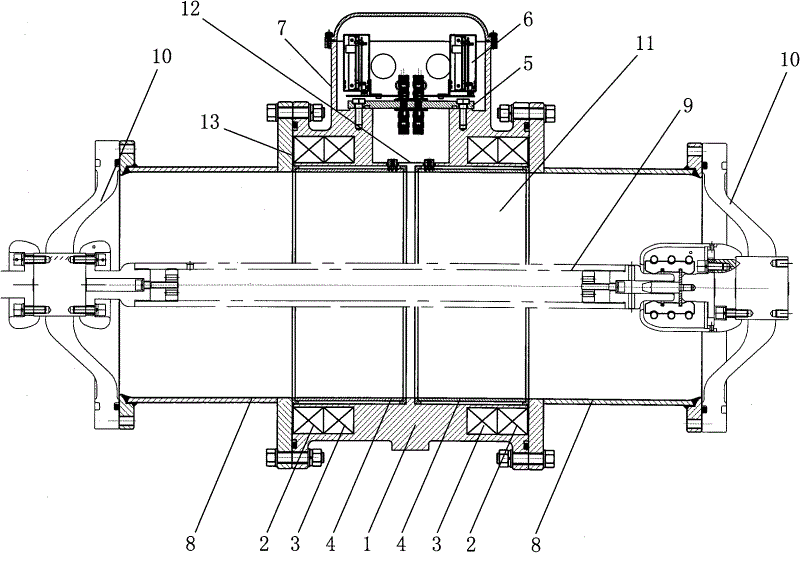
图1是本实用新型的组合剖视图;Fig. 1 is a combined sectional view of the utility model;
图2是本实用新型的侧视图。Fig. 2 is a side view of the utility model.
具体实施方式Detailed ways
以下将结合附图及具体实施例,对本实用新型的结构及工作原理进行详细说明。The structure and working principle of the present utility model will be described in detail below in conjunction with the accompanying drawings and specific embodiments.
配合图1所示,本实用新型提供一种电子式电流电压组合互感器,包括一个罐体1、两个空芯线圈2、两个LPCT(低功率电流互感器)3、两个电容分压环4、密封端子板5、远端模块6、箱体7、两个转接法兰8、一个一次导体9和两个盆式绝缘子10,下面分别介绍。As shown in Figure 1, the utility model provides an electronic current-voltage combined transformer, which includes a tank body 1, two air-
罐体1的内部具有一气室11,而顶部具有一连通气室11与外部的开口12,并在左右两侧各设有一个矩形槽13。The inside of the tank body 1 has an
两个空芯线圈2分别固定于罐体1的两个矩形槽13内,所述的空芯线圈2用于传感保护用电流信号,该空芯线圈2的输出信号是被测电流的微分,采用硬件积分技术对空芯线圈2输出的微分信号进行积分变换,这样可使LPCT 3的保护电流信号具有较大的动态范围及较好的暂态特性,满足继电保护的需求。Two air-
两个LPCT 3分别固定于罐体1的两个矩形槽13内,所述的LPCT 3用于传感测量用电流信号,这样可使其测量电流信号具有较高的测量准确度,满足电能计量的需求。Two
两个电容分压环4利用绝缘介质分别固定于罐体1内侧,且在本实施例中,将两个电容分压环4分别设于罐体1的上下两端。The two capacitive
罐体1的顶部开口12处固定有一箱体7,配合图2所示,该箱体7可用于屏蔽外部干扰信号,且对应罐体1的开口12具有上下贯通的通道。A
密封端子板5为金属材质,并具有玻璃烧结航空插头,所述的密封端子板5固定于箱体7内的通道上,并对应罐体1的开口12位置,一方面将空芯线圈2、LPCT 3及电容分压环4的输出信号引至气室11外,另一方面用于密封气室11内的气体;由于GIS断路器或隔离开关操作时会产生瞬态过电压(VFTO),因此采用密封端子板5可有效地防止VFTO对远端模块6的干扰。The sealed
罐体1的两侧分别设有一个转接法兰8,且两个转接法兰8的端部还分别固定有一个盆式绝缘子10,呈圆柱形的一次导体9的两端分别与两个盆式绝缘子10固定,并使得一次导体9位于两个电容分压环4之间,这样,两个电容分压环4均位于一次导体9和罐体1之间,电容分压环4与一次导体9构成高压电容C1,该高压电容的介质为SF6气体,而电容分压环4与罐体1构成低压电容C2,该低压电容的容值易受输出信号线分布电容的影响;为了提高电压测量的稳定性及暂态性能,在前述低压电容的两端并接一个温度系数为5ppm的小阻值精密电阻R(该电阻设于远端模块6内),所述电阻的阻值远小于低压电容的容抗

远端模块6也设于箱体7内,并固定于密封端子板5的外侧。The
工作时,空芯线圈2和LPCT 3用于传感被测的一次电流信息,其中,空芯线圈2传感保护用电流信号,LPCT 3传感测量用电流信号;而各电容分压环4与两侧的罐体1、一次导体9构成一个同轴电容分压器,且两个电容分压环4分别是这两个同轴电容分压器的中间电极,该同轴电容分压器用于传感被测一次电压信息,远端模块6就地采集并处理空芯线圈2、LPCT 3及同轴电容分压器的输出信号,对每个模拟输入信号远端模块均设计两路独立采样回路,完成双重化采样,实时比较、校验两路采样值,实现采样回路硬件自检功能,避免采样异常引起保护误动;而远端模块6的输出信号为数字信号,该输出信号利用光纤传输。When working, the air-
需要说明的是,本实用新型共配置两套空芯线圈2、LPCT 3、同轴电容分压器及远端模块6,两套测量元件互为备用,其中一套测量元件的故障不会影响另一套测量元件的正常工作,从而具有更高的可靠性。It should be noted that the utility model is equipped with two sets of air-
以上实施例仅为说明本实用新型的技术思想,不能以此限定本实用新型的保护范围,凡是按照本实用新型提出的技术思想,在技术方案基础上所做的任何改动,均落入本实用新型保护范围之内。The above embodiments are only to illustrate the technical ideas of the utility model, and cannot limit the protection scope of the utility model with this. Any changes made on the basis of the technical solutions according to the technical ideas proposed by the utility model all fall into the scope of the utility model. within the scope of the new protection.
Claims (2)
Priority Applications (1)
| Application Number | Priority Date | Filing Date | Title |
|---|---|---|---|
| CN201020535143XU CN201812667U (en) | 2010-09-16 | 2010-09-16 | Electronic current and voltage combined transformer |
Applications Claiming Priority (1)
| Application Number | Priority Date | Filing Date | Title |
|---|---|---|---|
| CN201020535143XU CN201812667U (en) | 2010-09-16 | 2010-09-16 | Electronic current and voltage combined transformer |
Publications (1)
| Publication Number | Publication Date |
|---|---|
| CN201812667U true CN201812667U (en) | 2011-04-27 |
Family
ID=43895606
Family Applications (1)
| Application Number | Title | Priority Date | Filing Date |
|---|---|---|---|
| CN201020535143XU Expired - Lifetime CN201812667U (en) | 2010-09-16 | 2010-09-16 | Electronic current and voltage combined transformer |
Country Status (1)
| Country | Link |
|---|---|
| CN (1) | CN201812667U (en) |
Cited By (13)
| Publication number | Priority date | Publication date | Assignee | Title |
|---|---|---|---|---|
| CN102496447A (en) * | 2011-12-01 | 2012-06-13 | 中国西电电气股份有限公司 | Electronic single-phase current voltage transformer for gas insulated metal-closed switchgear |
| CN102737826A (en) * | 2012-06-05 | 2012-10-17 | 平高集团有限公司 | Mutual inductor |
| CN102914680A (en) * | 2011-09-26 | 2013-02-06 | 北京航天时代光电科技有限公司 | Optical voltage transformer integrated in GIS cavity |
| CN103208360A (en) * | 2013-03-21 | 2013-07-17 | 许继集团有限公司 | Electronic-type current-voltage-combined transformer for GIS (gas insulated switchgear) |
| CN103208359A (en) * | 2013-03-21 | 2013-07-17 | 许继集团有限公司 | Electronic current and voltage combined transformer for support column type gas insulation |
| CN103545102A (en) * | 2013-10-22 | 2014-01-29 | 江苏靖江互感器厂有限公司 | Outdoor integral intelligent combined transformer |
| CN103730247A (en) * | 2013-12-17 | 2014-04-16 | 国家电网公司 | Full-shielding high-voltage isolated-type voltage transformer |
| CN105489361A (en) * | 2015-12-04 | 2016-04-13 | 国家电网公司 | Electronic current-voltage combined transducer for GIS |
| CN105575637A (en) * | 2015-12-23 | 2016-05-11 | 四方继保(武汉)软件有限公司 | Gas insulated switchgear (GIS) electronic type voltage transformer with suspension plate electrode structure |
| CN106501568A (en) * | 2016-12-23 | 2017-03-15 | 中国西电电气股份有限公司 | A kind of divider remote end module casing |
| CN109378194A (en) * | 2018-11-20 | 2019-02-22 | 许继(厦门)智能电力设备股份有限公司 | A kind of electronic current mutual inductor |
| CN110850137A (en) * | 2018-08-21 | 2020-02-28 | 西安西电高压开关有限责任公司 | Electronic transformer and data processing method |
| CN112449677A (en) * | 2018-11-20 | 2021-03-05 | Abb瑞士股份有限公司 | Device for monitoring the temperature and voltage of a cable joint of a cable connected to a gas-insulated switchgear and associated manufacturing method |
-
2010
- 2010-09-16 CN CN201020535143XU patent/CN201812667U/en not_active Expired - Lifetime
Cited By (23)
| Publication number | Priority date | Publication date | Assignee | Title |
|---|---|---|---|---|
| CN102914680A (en) * | 2011-09-26 | 2013-02-06 | 北京航天时代光电科技有限公司 | Optical voltage transformer integrated in GIS cavity |
| CN102914680B (en) * | 2011-09-26 | 2013-06-19 | 北京航天时代光电科技有限公司 | Optical voltage transformer integrated in GIS cavity |
| CN102496447B (en) * | 2011-12-01 | 2015-04-22 | 中国西电电气股份有限公司 | Electronic single-phase current voltage transformer for gas insulated metal-closed switchgear |
| CN102496447A (en) * | 2011-12-01 | 2012-06-13 | 中国西电电气股份有限公司 | Electronic single-phase current voltage transformer for gas insulated metal-closed switchgear |
| CN102737826A (en) * | 2012-06-05 | 2012-10-17 | 平高集团有限公司 | Mutual inductor |
| CN102737826B (en) * | 2012-06-05 | 2014-03-12 | 平高集团有限公司 | Mutual inductor |
| CN103208360B (en) * | 2013-03-21 | 2016-04-20 | 许继集团有限公司 | A kind of GIS electronic current-voltage combination transformer |
| CN103208360A (en) * | 2013-03-21 | 2013-07-17 | 许继集团有限公司 | Electronic-type current-voltage-combined transformer for GIS (gas insulated switchgear) |
| CN103208359A (en) * | 2013-03-21 | 2013-07-17 | 许继集团有限公司 | Electronic current and voltage combined transformer for support column type gas insulation |
| CN103208359B (en) * | 2013-03-21 | 2016-04-20 | 许继集团有限公司 | A kind of column support type gas-insulated electronic current-voltage combination transformer |
| CN103545102A (en) * | 2013-10-22 | 2014-01-29 | 江苏靖江互感器厂有限公司 | Outdoor integral intelligent combined transformer |
| WO2015090119A1 (en) * | 2013-12-17 | 2015-06-25 | 国家电网公司 | Full-shielding high-voltage isolated-type voltage transformer |
| CN103730247A (en) * | 2013-12-17 | 2014-04-16 | 国家电网公司 | Full-shielding high-voltage isolated-type voltage transformer |
| CN103730247B (en) * | 2013-12-17 | 2016-04-20 | 国家电网公司 | A kind of full-shield high_voltage isolation type voltage transformer |
| CN105489361A (en) * | 2015-12-04 | 2016-04-13 | 国家电网公司 | Electronic current-voltage combined transducer for GIS |
| CN105489361B (en) * | 2015-12-04 | 2018-08-03 | 国家电网公司 | GIS electronic current-voltage combination transformers |
| CN105575637A (en) * | 2015-12-23 | 2016-05-11 | 四方继保(武汉)软件有限公司 | Gas insulated switchgear (GIS) electronic type voltage transformer with suspension plate electrode structure |
| CN105575637B (en) * | 2015-12-23 | 2017-11-24 | 四方继保(武汉)软件有限公司 | A kind of GIS electronic type voltage transformers of suspension plate electrode structures |
| CN106501568A (en) * | 2016-12-23 | 2017-03-15 | 中国西电电气股份有限公司 | A kind of divider remote end module casing |
| CN110850137A (en) * | 2018-08-21 | 2020-02-28 | 西安西电高压开关有限责任公司 | Electronic transformer and data processing method |
| CN110850137B (en) * | 2018-08-21 | 2022-07-12 | 西安西电高压开关有限责任公司 | Electronic transformer and data processing method |
| CN109378194A (en) * | 2018-11-20 | 2019-02-22 | 许继(厦门)智能电力设备股份有限公司 | A kind of electronic current mutual inductor |
| CN112449677A (en) * | 2018-11-20 | 2021-03-05 | Abb瑞士股份有限公司 | Device for monitoring the temperature and voltage of a cable joint of a cable connected to a gas-insulated switchgear and associated manufacturing method |
Similar Documents
| Publication | Publication Date | Title |
|---|---|---|
| CN201812668U (en) | Electronic type current and voltage combined mutual inductor of three-phase enclosed GIS (Geographic Information System) | |
| CA2925370C (en) | A high voltage divider | |
| CN109521265B (en) | A voltage and current combined digital electronic transformer | |
| CN110646663A (en) | Primary and secondary depth fusion combined sensor for vacuum circuit breaker | |
| CN103426620B (en) | Open-close type electronic current transformer | |
| CN111863508A (en) | A tie-column circuit breaker with deep integration of primary and secondary | |
| CN110600251A (en) | Combined voltage transformer with zero sequence voltage output function | |
| CN108493821A (en) | Automatic Switching on a kind of distribution net post using electronic sensor | |
| CN209513903U (en) | A kind of digital electric mutual inductor of voltage and current combination | |
| CN114242509A (en) | Breaker on deep fusion column | |
| CN212083523U (en) | Coaxial capacitance voltage division type sleeve type voltage sensor | |
| CN101770855A (en) | Electronic combined transformer for digitalized power station | |
| CN100376897C (en) | A high-voltage signal sampling method that can meet the needs of metering, measurement or protection | |
| CN110412328B (en) | Combined electronic transformer for distribution transformer and measuring system | |
| CN203552926U (en) | Electronic current transformer for disconnecting circuit breaker | |
| CN202548179U (en) | Optical current mutual inductor component with secondary conversion equipment | |
| CN106253087B (en) | A smart ring network cabinet | |
| CN211905469U (en) | Three-phase three-wire high-voltage electric energy metering box of four fuses | |
| CN109324306B (en) | GIS equipment current transformer error testing system and construction method thereof | |
| CN203324347U (en) | Electronic transformer | |
| CN111693750A (en) | Intelligent cable voltage sensor | |
| CN201498356U (en) | Electronic combined power mutual inductor | |
| CN201117420Y (en) | Electronic voltage transformer | |
| CN110031661A (en) | A kind of voltage transformer being isolated with high pressure and low pressure | |
| CN209803216U (en) | A voltage transformer with high voltage and low voltage isolation |
Legal Events
| Date | Code | Title | Description |
|---|---|---|---|
| C14 | Grant of patent or utility model | ||
| GR01 | Patent grant | ||
| CX01 | Expiry of patent term |
Granted publication date: 20110427 |
|
| CX01 | Expiry of patent term |