CN201781331U - Adapter with wireless charging - Google Patents
Adapter with wireless charging Download PDFInfo
- Publication number
- CN201781331U CN201781331U CN2010201754249U CN201020175424U CN201781331U CN 201781331 U CN201781331 U CN 201781331U CN 2010201754249 U CN2010201754249 U CN 2010201754249U CN 201020175424 U CN201020175424 U CN 201020175424U CN 201781331 U CN201781331 U CN 201781331U
- Authority
- CN
- China
- Prior art keywords
- circuit
- adapter
- signal
- wireless charging
- resonance
- Prior art date
- Legal status (The legal status is an assumption and is not a legal conclusion. Google has not performed a legal analysis and makes no representation as to the accuracy of the status listed.)
- Expired - Fee Related
Links
- 230000000087 stabilizing effect Effects 0.000 claims description 12
- 238000001914 filtration Methods 0.000 claims description 11
- 230000006698 induction Effects 0.000 claims description 11
- 230000003321 amplification Effects 0.000 claims description 2
- 238000003199 nucleic acid amplification method Methods 0.000 claims description 2
- 230000009514 concussion Effects 0.000 claims 7
- 238000009434 installation Methods 0.000 claims 7
- NJPPVKZQTLUDBO-UHFFFAOYSA-N novaluron Chemical compound C1=C(Cl)C(OC(F)(F)C(OC(F)(F)F)F)=CC=C1NC(=O)NC(=O)C1=C(F)C=CC=C1F NJPPVKZQTLUDBO-UHFFFAOYSA-N 0.000 claims 6
- 238000006243 chemical reaction Methods 0.000 claims 1
- 230000005540 biological transmission Effects 0.000 abstract description 5
- 238000010586 diagram Methods 0.000 description 14
- 230000010355 oscillation Effects 0.000 description 10
- 238000001514 detection method Methods 0.000 description 7
- WHXSMMKQMYFTQS-UHFFFAOYSA-N Lithium Chemical compound [Li] WHXSMMKQMYFTQS-UHFFFAOYSA-N 0.000 description 1
- 230000009286 beneficial effect Effects 0.000 description 1
- 239000004020 conductor Substances 0.000 description 1
- 238000005516 engineering process Methods 0.000 description 1
- 230000006870 function Effects 0.000 description 1
- 229910052744 lithium Inorganic materials 0.000 description 1
- 229910052987 metal hydride Inorganic materials 0.000 description 1
- 238000000034 method Methods 0.000 description 1
- 230000008450 motivation Effects 0.000 description 1
- 229910052759 nickel Inorganic materials 0.000 description 1
- PXHVJJICTQNCMI-UHFFFAOYSA-N nickel Substances [Ni] PXHVJJICTQNCMI-UHFFFAOYSA-N 0.000 description 1
- -1 nickel metal hydride Chemical class 0.000 description 1
Images






Landscapes
- Charge And Discharge Circuits For Batteries Or The Like (AREA)
Abstract
Description
技术领域technical field
本实用新型是有关于一种充电装置,特别是指一种可应用于转接器等相关领域的充电装置。 The utility model relates to a charging device, in particular to a charging device applicable to adapters and other related fields. the
背景技术Background technique
近年来,由于科技不断的进步,人们对于电子产品的要求也相对地提高,尤以消费性电子商品为主,以往体积庞大的电子产品(如光盘播放器、家用电话或桌上型计算机等)精简化变成可携带且效能高的电子产品(如多媒体播放器(MPEG Audio Layer-3,MP3)、行动电话或笔记型计算机等),以使人们的生活更加有效率。 In recent years, due to the continuous advancement of science and technology, people's requirements for electronic products have also increased relatively, especially consumer electronic products. In the past, bulky electronic products (such as CD players, home phones or desktop computers, etc.) Simplified into portable and high-performance electronic products (such as multimedia players (MPEG Audio Layer-3, MP3), mobile phones or notebook computers, etc.), to make people's lives more efficient. the
上述的多媒体播放器、行动电话等携带式电子产品于使用时所需的电力,大多采用如镍氢电池或锂电池等充电电池,该充电电池主要是由一充电装置进行充电,该充电装置是包括一充电座及一插座,该充电座与该插座以有线方式连接,且该充电座设有一充电槽,以供该充电电池放置于该充电槽中,而该插座则插设于电源插座,以提供充电时所需的电压或电流,该笔记型计算机则需由一转接器与电源插座连接,由该转接器提供该笔记型计算机所需的电压或电流。然而,由于上述携带式电子产品须由转接器或充电电池提供所需的电力,人们若外出需使用该些携带式电子产品时,需携带不同转接器或专用充电器,使其外出或洽公时不便携带,降低使用便利性,另外,由于上述充电装置或转接器是将充电所需的电能由有线线路连结传递至该充电电池,使其使用范围有限。 The above-mentioned portable electronic products such as multimedia players and mobile phones use rechargeable batteries such as nickel metal hydride batteries or lithium batteries mostly for the power required in use. The rechargeable batteries are mainly charged by a charging device. The charging device is It includes a charging stand and a socket, the charging stand is connected to the socket in a wired manner, and the charging stand is provided with a charging slot for the rechargeable battery to be placed in the charging slot, and the socket is plugged into a power socket, To provide the required voltage or current for charging, the notebook computer needs to be connected to the power socket through an adapter, and the adapter provides the required voltage or current for the notebook computer. However, since the above-mentioned portable electronic products must be powered by adapters or rechargeable batteries, if people need to use these portable electronic products when they go out, they need to carry different adapters or special chargers to make them go out or use them. It is inconvenient to carry when contacting business, which reduces the convenience of use. In addition, because the above-mentioned charging device or adapter transmits the electric energy required for charging to the rechargeable battery through a wired connection, its range of use is limited. the
有鉴于此,本实用新型人乃潜心研思、设计组制,期能提供一种携带方便且不受范围限制的具有无线充电的转接器,为本实用新型所欲研创的创作动机。 In view of this, the inventor of this utility model has devoted himself to research, design and assembly, hoping to provide an adapter with wireless charging that is convenient to carry and not limited by range, which is the motivation for the creation of this utility model. the
实用新型内容Utility model content
本实用新型的主要目的,在于提供一种具有无线充电的转接器,使其提供至少一电子产品不需分别连接各种充电器即可同时充电。 The main purpose of the present invention is to provide an adapter with wireless charging, so that at least one electronic product can be charged at the same time without being connected to various chargers separately. the
本实用新型的另一目的,在于提供一种具有无线充电的转接器,达到可无线充电以避免使用范围有限的目的。 Another object of the present invention is to provide an adapter with wireless charging to achieve the purpose of wireless charging to avoid limited use range. the
为达上述目的,本实用新型的具有无线充电的转接器是包括:应用于至少一电子装置,该电子装置设有一接收电路,该具有无线充电的转接器包括:一本体,是与该电子装置接触连接,且该本体包括有一电源件以及至少一发射电路,该电源件提供电力至该发射电路,该电力由该发射电路转换成该交流信号,该交流信号由该发射电路无线发送至一电子装置的接收电路,该接收电路将该交流信号转换成电力而能进行充电。 In order to achieve the above purpose, the adapter with wireless charging of the present invention includes: applied to at least one electronic device, the electronic device is provided with a receiving circuit, the adapter with wireless charging includes: a body, which is compatible with the The electronic device is contacted and connected, and the body includes a power supply and at least one transmitting circuit, the power supply supplies power to the transmitting circuit, the power is converted by the transmitting circuit into the AC signal, and the AC signal is wirelessly sent by the transmitting circuit to A receiving circuit of an electronic device, the receiving circuit converts the AC signal into electric power for charging. the
其中,该本体包括一座体及至少一盖体,该电源件与该座体连接,该盖体连接于该座体的侧边,而发射电路设于该座体及该盖体的其中之一上。 Wherein, the body includes a seat and at least one cover, the power supply is connected to the seat, the cover is connected to the side of the seat, and the transmitting circuit is arranged on one of the seat and the cover superior. the
其中,该电子装置与该座体及该盖体的其中之一结合。 Wherein, the electronic device is combined with one of the base body and the cover body. the
其中,该盖体枢接于该座体的侧边。 Wherein, the cover is pivotally connected to the side of the seat. the
其中,该本体与该电子装置的连接方式为凹凸槽定位、磁性定位、音控定位及光源定位的其中的一种。 Wherein, the connection mode between the body and the electronic device is one of concave-convex groove positioning, magnetic positioning, sound control positioning and light source positioning. the
其中,该本体与该电子装置为磁性定位,且该本体设有磁性体、导磁件及散热片,该导磁件设于该磁性体与该散热件之间。 Wherein, the main body and the electronic device are magnetically positioned, and the main body is provided with a magnetic body, a magnetic conductive part and a heat sink, and the magnetic conductive part is arranged between the magnetic body and the heat sink. the
其中,该发射电路包括震荡除频电路、驱动放大电路、一次发射共振电路及发射线圈,该震荡除频电路与该电源件连接,该震荡除频电路将该电源件提供的电力转换成交流信号,该驱动放大电路与该震荡除频电路连接,该驱动放大电路将该震荡除频电路所转换的交流信号放大,该一次发射共振电路与该驱动放大电路连接,该一次发射共振电路将该驱动放大电路所放大的交流信号取得谐振,该发射线圈与该一次发射共振电路连接,该发射线圈将该一次发射共振电路所取得谐振的交流信号发送至该接收电路。 Wherein, the transmitting circuit includes an oscillating frequency-dividing circuit, a drive amplifier circuit, a primary transmitting resonant circuit and a transmitting coil, the oscillating frequency-dividing circuit is connected with the power supply, and the oscillating frequency-dividing circuit converts the power provided by the power supply into an AC signal , the drive amplifier circuit is connected with the oscillation frequency divider circuit, the drive amplifier circuit amplifies the AC signal converted by the oscillation frequency divider circuit, the primary emission resonance circuit is connected with the drive amplification circuit, and the primary emission resonance circuit drives the The AC signal amplified by the amplifying circuit is resonant, the transmitting coil is connected to the primary transmitting resonant circuit, and the transmitting coil sends the resonant AC signal obtained by the primary transmitting resonant circuit to the receiving circuit. the
其中,该发射电路进一步包括回馈侦测电路及控制调整电路,该回馈 侦测电路与该发射线圈连接,且该控制调整电路与该回馈侦测电路及该震荡除频电路连接,该回馈侦测电路将该发射线圈所发送的交流信号回馈至该控制调整电路,该控制调整电路调整该震荡除频电路的震荡频率。 Wherein, the transmission circuit further includes a feedback detection circuit and a control adjustment circuit, the feedback detection circuit is connected with the transmission coil, and the control adjustment circuit is connected with the feedback detection circuit and the oscillation frequency division circuit, the feedback detection circuit The circuit feeds back the AC signal sent by the transmitting coil to the control adjustment circuit, and the control adjustment circuit adjusts the oscillation frequency of the oscillation frequency-dividing circuit. the
其中,该接收电路包括接收感应线圈、二次接收共振电路、AC/DC整流滤波稳压电路及充电电池,该接收感应线圈接收该发射电路所发送的交流信号,该二次接收共振电路与该接收感应线圈连接,该二次接收共振电路将该接收感应线圈所接收的交流信号取得谐振,该AC/DC整流滤波稳压电路与该二次接收共振电路连接,该AC/DC整流滤波稳压电路将该二次接收共振电路所取得谐振的交流信号进行整流及稳压,并将该交流信号转换成电力,该AC/DC整流滤波稳压电路与该充电电池连接,该充电电池储存由该AC/DC整流滤波稳压电路所转换的电力。 Wherein, the receiving circuit includes a receiving induction coil, a secondary receiving resonance circuit, an AC/DC rectification, filtering and voltage stabilizing circuit, and a rechargeable battery. The receiving induction coil receives the AC signal sent by the transmitting circuit, and the secondary receiving resonance circuit and the The receiving induction coil is connected, and the secondary receiving resonance circuit resonates the AC signal received by the receiving induction coil. The circuit rectifies and stabilizes the resonant AC signal obtained by the secondary receiving resonance circuit, and converts the AC signal into electric power. The AC/DC rectifying, filtering and stabilizing circuit is connected to the rechargeable battery, which is stored by the The power converted by the AC/DC rectification, filtering and voltage stabilizing circuit. the
本实用新型的有益效果是:其可提供至少一电子产品不需分别连接各种充电器即能同时充电,并可避免因需由充电器有线连接充电而造成使用范围有限的问题,提高其使用便利性的效用。 The beneficial effect of the utility model is that it can provide at least one electronic product that can be charged at the same time without being connected to various chargers separately, and can avoid the problem of limited range of use caused by the need for wired connection and charging of the charger, and improve its usability. The utility of convenience. the
附图说明Description of drawings
为了能够更进一步了解本实用新型的特征、特点和技术内容,请参阅以下有关本实用新型的详细说明与附图,惟所附附图仅提供参考与说明用,非用以限制本实用新型,其中: In order to further understand the features, characteristics and technical contents of the present utility model, please refer to the following detailed description and accompanying drawings of the present utility model, but the accompanying drawings are only for reference and illustration, and are not intended to limit the present utility model. in:
图1是本实用新型的具有无线充电的转接器的第一实施例立体结构示意图。 FIG. 1 is a schematic perspective view of the first embodiment of the wireless charging adapter of the present invention. the
图2为本实用新型的具有无线充电的转接器的第一实施例立体结构剖面示意图。 FIG. 2 is a schematic cross-sectional view of the three-dimensional structure of the first embodiment of the adapter with wireless charging of the present invention. the
图3为本实用新型的具有无线充电的转接器的第一实施例使用状态示意图。 FIG. 3 is a schematic diagram of the use state of the first embodiment of the adapter with wireless charging of the present invention. the
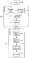
图4A至图4B为本实用新型的具有无线充电的转接器的第一实施例电路方块示意图。 4A to 4B are circuit block diagrams of the first embodiment of the adapter with wireless charging of the present invention. the
图5为本实用新型的具有无线充电的转接器的第二实施例立体结构展开示意图。 FIG. 5 is a schematic diagram showing the three-dimensional structure development of the second embodiment of the adapter with wireless charging of the present invention. the
图6为本实用新型的具有无线充电的转接器的第二实施例立体结构收 合示意图。 Fig. 6 is a schematic diagram of the three-dimensional structure of the second embodiment of the wireless charging adapter of the present invention. the
图7为本实用新型的具有无线充电的转接器的第二实施例使用状态示意图。 FIG. 7 is a schematic diagram of the use state of the second embodiment of the adapter with wireless charging of the present invention. the
图8为本实用新型的具有无线充电的转接器的第三实施例立体结构展开示意图。 FIG. 8 is a schematic exploded view of the three-dimensional structure of the third embodiment of the adapter with wireless charging of the present invention. the
图9为本实用新型的具有无线充电的转接器的第三实施例立体结构收合示意图。 FIG. 9 is a schematic view of the three-dimensional structure of the third embodiment of the adapter with wireless charging of the present invention. the
具体实施方式Detailed ways
第一实施例 first embodiment
请参阅图1至图4B所示,是为本实用新型的具有无线充电的转接器的第一实施例立体结构示意图、立体结构剖面示意图、使用状态示意图及其电路方块示意图。该具有无线充电的转接器是包括本体100,该本体100设有发射电路140,使用者可任意将设有接收电路210的电子装置200定位于该本体100上,以供可由无线传输方式执行充电的工作。 Please refer to FIG. 1 to FIG. 4B , which are the three-dimensional structure schematic diagram, the three-dimensional structure cross-sectional schematic diagram, the use state schematic diagram and the circuit block schematic diagram of the first embodiment of the wireless charging adapter of the present invention. The adapter with wireless charging includes a
该本体100是为转接器(Adapter),且该本体100是包括有至少一发射电路140、连接件150、磁性体160、导磁件170及散热片180,该磁性体160设于该本体100的一侧,且该导磁件170设于该磁性体160与该散热件180之间,该些发射电路140设置于该本体100上,以供该电源件130提供电力至该发射电路140,该电力由该发射电路140转换成该交流信号,该交流信号由该发射电路140无线发送至该电子装置200的接收电路210,以供该接收电路210将该交流信号转换成电力,以储存该电力并供电给该电子装置200。 The
该发射电路140是包括一与该电源件130连接的震荡除频电路141、一与该震荡除频电路141连接的驱动放大电路142、一与该驱动放大电路142连接的一次发射共振电路143以及一与该一次发射共振电路143连接的发射线圈144,以由该震荡除频电路141将该电源件130提供的电力转换成交流信号,且该交流信号经由该驱动放大电路142放大后,可由该一次发射共振电路143将放大后的交流信号取得谐振,再由该发射线圈144发送至该接收电路210(如图4A所示,为该发射电路140较佳地实施态 样),其中,该交流信号可由该导磁件170集中发送,而该散热片180可将该本体100使用时所产生的热量散发。 The transmitting
另外,如图4B所示,最佳地,该发射电路140亦可包括一与该发射线圈144连接的回馈侦测电路145以及一与该回馈侦测电路145及该震荡除频电路141连接的控制调整电路146,以由该回馈侦测电路145将该发射线圈144所发送的交流信号回馈至该控制调整电路146,使该控制调整电路146调整该震荡除频电路141的震荡频率,进而取得最佳谐振品质。 In addition, as shown in FIG. 4B , optimally, the transmitting
该电子装置200可为多媒体播放器、行动电话等携带式电子产品,该电子装置200可由凹凸槽定位(如该电子装置200及该本体100可分别设有相对应的凹、凸槽)、磁性定位(如该本体100及该电子装置200可分别设有相对应的正、负极磁性体)、音控定位(如该本体100及该电子装置200可分别设有相对应的音源感应器)及光源定位(如该本体100及该电子装置200可分别设有相对应的光源感应器)等方式连接于该本体100上。而设于该电子装置200上的接收电路210包括一接收感应线圈211、一与该接收感应线圈211连接的二次接收共振电路212、一与该二次接收共振电路212连接的AC/DC整流滤波稳压电路213以及一与该AC/DC整流滤波稳压电路213连接的充电电池214,以由该接收感应线圈211接收该发射电路140所发送的交流信号,且该交流信号经由该二次接收共振电路212取得谐振,并由该AC/DC整流滤波稳压电路213将该交流信号进行整流、稳压,使该交流信号转换成电力,该电力由该充电电池214储存,进而由该充电电池214提供该电子装置200电源。 The
于本实施例中,该本体100是为笔记型计算机(Notebook,NB)的转接器,该本体100设有发射电路140、磁性体160(如磁铁)、导磁件170及散热片180,且该本体100的两端分别连接有电源件130及连接件150,该本体100可由该连接件150与一笔记型计算机300电性连接,当使用者欲将设有磁性体220的电子装置200(如多媒体播放器、行动电话)进行充电时,可由该电子装置200的磁性体220与该本体100的磁性体160相互吸引,而使该电子装置200接触连接于该本体100上,且该电源件130插设于一电源插座400上,以由该电源件130提供电力至该发射电路140,该电力经由该发射电路140转换成交流信号,并通过该发射电路140的发射 线圈144将该交流信号发送至各该电子装置200的接收电路210,以供对该接收电路210进行充电而能供电给该电子装置200,亦即,由本实用新型一机多用的设计,可供至少一电子产品不需分别连接各种充电器即能同时充电,且可避免因需由充电器有线连接充电而造成使用范围有限的问题,提高其使用便利性。 In this embodiment, the
第二实施例 Second embodiment
请参阅图5至图7所示,是为本实用新型的具有无线充电的转接器的第二实施例立体结构展开示意图、立体结构收合示意图及其使用状态示意图。其中,本实施例与第一实施例相同,其主要差别是在于该本体100包括一座体110及一盖体120,该盖体120设于该座体110的一侧边,以供该盖体120可相对于该座体110移动或转动,亦即,当该盖体120以远离该座体110的方向移动或转动时,可使该座体110与该盖体120为展开状态(如图5所示),以供该电子装置200可定位于座体110或盖体120上,亦即,该电子装置200可仅连接于该座体110上、或该电子装置200仅连接于盖体120上、或该座体110及该盖体120上分别连接有电子装置200;当该盖体120以朝向该座体110的方向移动或转动时,则使该盖体120收合于该座体110的表面上(如图6所示)。 Please refer to FIG. 5 to FIG. 7 , which are schematic diagrams of the three-dimensional structure of the second embodiment of the adapter with wireless charging of the present invention, a schematic diagram of the three-dimensional structure of the folded structure and a schematic diagram of its use state. Among them, this embodiment is the same as the first embodiment, the main difference is that the
于本实施利中,该盖体120是枢接于该座体110的一侧边,可将该盖体120以远离该座体110的方向转动,使该座体110与该盖体120为展开状态,以供二电子装置200定位于该座体110及该盖体120上,使各该电子装置200可实时充电,且当使用者不需使用时,可将该盖体120以朝向该座体110的方向转动,使该盖体120收合于该座体110上,以供可依据使用者的需求展开或收合,具有携带方便及易于收纳的优点。 In this embodiment, the
第三实施例 third embodiment
请参阅图8至图9所示,是为本实用新型的具有无线充电的转接器的第三实施例立体结构展开示意图及其立体结构收合示意图。其中,本实施例与第二实施例相同,其主要差别是在于该本体100包括一座体110及二盖体120,该二盖体120分别设于该座体110的二侧边,可将各该盖体120以远离该座体110的方向移动或转动,使该座体110与各该盖体120为展开状态,可将至少二电子装置200分别连接于该座体110及各该盖体120 上,使各该电子装置200可实时充电,且当使用者不需使用时,可将各该盖体120以朝向该座体110的方向移动或转动,使各该盖体120收合于该座体110上,具有易于收纳及携带方便的功效。 Please refer to FIG. 8 to FIG. 9 , which are schematic diagrams of the three-dimensional structure of the third embodiment of the adapter with wireless charging of the present invention and a schematic diagram of the three-dimensional structure of the collapsed structure. Wherein, the present embodiment is the same as the second embodiment, and the main difference is that the
综上所述,本实用新型的具有无线充电的转接器主要是于本体100上设有发射电路140,令使用者欲将设有接收电路210的电子装置200进行充电时,可将该电子装置200接触连接于该本体100上,由该发射电路140以无线传输方式发送一交流信号至该接收电路210,以供该接收电路210进行充电,以储存电力并供电给该电子装置200,使其具有一机多用设计的特点,可提供至少一电子产品不需分别连接各种充电器即能同时充电,使其携带方便且易于收纳,并可避免因需由充电器有线连接充电而造成使用范围有限的问题,提高其使用便利性的效用。 To sum up, the wireless charging adapter of the present invention is mainly provided with a transmitting
以上所述仅为本实用新型的较佳可行实施例,非因此即局限本实用新型的专利范围,凡是运用本实用新型说明书及附图内容所为的等效结构变化,均理同包含于本实用新型的范围内。 The above descriptions are only preferred feasible embodiments of the present utility model, and are not intended to limit the patent scope of the present utility model. All equivalent structural changes made by using the description of the utility model and the contents of the accompanying drawings are all included in this utility model. within the scope of utility models. the
Claims (9)
Priority Applications (1)
| Application Number | Priority Date | Filing Date | Title |
|---|---|---|---|
| CN2010201754249U CN201781331U (en) | 2010-04-16 | 2010-04-16 | Adapter with wireless charging |
Applications Claiming Priority (1)
| Application Number | Priority Date | Filing Date | Title |
|---|---|---|---|
| CN2010201754249U CN201781331U (en) | 2010-04-16 | 2010-04-16 | Adapter with wireless charging |
Publications (1)
| Publication Number | Publication Date |
|---|---|
| CN201781331U true CN201781331U (en) | 2011-03-30 |
Family
ID=43794533
Family Applications (1)
| Application Number | Title | Priority Date | Filing Date |
|---|---|---|---|
| CN2010201754249U Expired - Fee Related CN201781331U (en) | 2010-04-16 | 2010-04-16 | Adapter with wireless charging |
Country Status (1)
| Country | Link |
|---|---|
| CN (1) | CN201781331U (en) |
Cited By (4)
| Publication number | Priority date | Publication date | Assignee | Title |
|---|---|---|---|---|
| CN104348208A (en) * | 2013-08-09 | 2015-02-11 | 全亿大科技(佛山)有限公司 | Charging device |
| CN104426244A (en) * | 2013-08-23 | 2015-03-18 | 全亿大科技(佛山)有限公司 | Wireless charging device |
| CN106160256A (en) * | 2015-05-11 | 2016-11-23 | 现代自动车株式会社 | Wireless charging device |
| CN108418282A (en) * | 2018-04-27 | 2018-08-17 | 深圳市智创无限科技有限公司 | Wireless charger structure |
-
2010
- 2010-04-16 CN CN2010201754249U patent/CN201781331U/en not_active Expired - Fee Related
Cited By (7)
| Publication number | Priority date | Publication date | Assignee | Title |
|---|---|---|---|---|
| CN104348208A (en) * | 2013-08-09 | 2015-02-11 | 全亿大科技(佛山)有限公司 | Charging device |
| CN104348208B (en) * | 2013-08-09 | 2018-09-25 | 全亿大科技(佛山)有限公司 | Charging unit |
| CN104426244A (en) * | 2013-08-23 | 2015-03-18 | 全亿大科技(佛山)有限公司 | Wireless charging device |
| CN104426244B (en) * | 2013-08-23 | 2018-07-31 | 苏州彤帆智能科技有限公司 | Wireless charging device |
| CN106160256A (en) * | 2015-05-11 | 2016-11-23 | 现代自动车株式会社 | Wireless charging device |
| CN106160256B (en) * | 2015-05-11 | 2021-07-16 | 现代自动车株式会社 | wireless charging device |
| CN108418282A (en) * | 2018-04-27 | 2018-08-17 | 深圳市智创无限科技有限公司 | Wireless charger structure |
Similar Documents
| Publication | Publication Date | Title |
|---|---|---|
| JP3169751U (en) | Adapter with wireless charging function | |
| JP3169916U (en) | Double-sided rechargeable wireless charging stand | |
| JP3168006U (en) | Notebook with wireless charging function | |
| CN204131179U (en) | Wireless charging stand that can lie flat or charge at an angle | |
| JP3144849U (en) | Sensing power supply | |
| CN201654673U (en) | Notebook computer with wireless charging function | |
| KR101620628B1 (en) | Headset wireless charging system | |
| JP3169709U (en) | Electronic book with wireless charging function | |
| CN204167924U (en) | Wireless charging device | |
| TWM461243U (en) | Wireless charging device | |
| US20120001589A1 (en) | Bidirectional wireless charging/discharging device | |
| CN110739744B (en) | A mobile phone wireless power bank with a mobile phone holder | |
| CN210120415U (en) | Wireless charger | |
| US9325199B2 (en) | Wireless charging device | |
| CN203708367U (en) | Projector | |
| US12074454B1 (en) | Double-sided wireless charger | |
| CN201774285U (en) | Double-sided wireless charging stand | |
| CN201750234U (en) | eBooks with Wireless Charging | |
| CN201733141U (en) | Electronic device | |
| CN203180655U (en) | Wireless power supply equipment | |
| CN203707834U (en) | Wireless charging device with storage function | |
| CN201781041U (en) | Rubber band type wireless charging protective sleeve | |
| TW201443612A (en) | Multifunctional component combined with portable electronic device | |
| TWM393910U (en) | Wireless charging protection cover of rubber band type | |
| CN201877846U (en) | Wireless charging connector |
Legal Events
| Date | Code | Title | Description |
|---|---|---|---|
| C14 | Grant of patent or utility model | ||
| GR01 | Patent grant | ||
| CF01 | Termination of patent right due to non-payment of annual fee |
Granted publication date: 20110330 Termination date: 20180416 |
|
| CF01 | Termination of patent right due to non-payment of annual fee |