CN201728789U - Hot pressing die ejector plate guide device - Google Patents
Hot pressing die ejector plate guide device Download PDFInfo
- Publication number
- CN201728789U CN201728789U CN2010202696236U CN201020269623U CN201728789U CN 201728789 U CN201728789 U CN 201728789U CN 2010202696236 U CN2010202696236 U CN 2010202696236U CN 201020269623 U CN201020269623 U CN 201020269623U CN 201728789 U CN201728789 U CN 201728789U
- Authority
- CN
- China
- Prior art keywords
- guide
- ejector plate
- pillars
- die pad
- length direction
- Prior art date
- Legal status (The legal status is an assumption and is not a legal conclusion. Google has not performed a legal analysis and makes no representation as to the accuracy of the status listed.)
- Expired - Lifetime
Links
- 238000007731 hot pressing Methods 0.000 title abstract description 5
- 238000004519 manufacturing process Methods 0.000 abstract description 2
- 238000010438 heat treatment Methods 0.000 description 3
- 238000003825 pressing Methods 0.000 description 3
- 230000010339 dilation Effects 0.000 description 2
- 238000005516 engineering process Methods 0.000 description 2
- 238000004458 analytical method Methods 0.000 description 1
- 239000000463 material Substances 0.000 description 1
- 230000013011 mating Effects 0.000 description 1
- 238000000034 method Methods 0.000 description 1
- 238000000465 moulding Methods 0.000 description 1
Images

Landscapes
- Mounting, Exchange, And Manufacturing Of Dies (AREA)
Abstract
The utility model belongs to the technical field of molds, in particular to a hot pressing die ejector plate guide device of a hot press forming machine. The hot pressing die ejector plate guide device comprises an upper die, a lower die, a lower die insert and an ejector plate, two guide pillars are uniformly arranged on the bottom surface of the ejector plate along the length direction, two guide bushes are arranged in the lower die corresponding to the guide pillars, the two guide pillars are respectively disposed in the guide bushes fittingly and are cylinders, two sides of each guide pillar corresponding to the width of the ejector plate are planes, two sides of an inner bore of each guide bush corresponding to each guide pillar are planes, and the guide pillars and the guide bushes are in clearance fit corresponding to the length direction of the ejector plate. The hot pressing die ejector plate guide device effectively resolves the problem that operation is affected by difference of thermal expansion degrees of the guide pillars and the guide bushes in a redial length direction, prolongs service life of the guide pillars and saves production cost.
Description
Technical field
The utility model belongs to technical field of mold, is specifically related to the hot pressure-shaped mould die pad of heat pressing forming machines guider.
Background technology
A large amount of heat pressing forming machines that use in existing plate forming technology, the hot pressure-shaped mould of U-shaped plate is the key equipment during heat pressing forming machines uses; The die pad guider of the guide pillars and bushes composition that in the past adopted is when work, the blank of heating is because directly contact die pad, being fixed on the die pad upper guide post and being fixed on the interior guide pin bushing of counterdie influenced by hotline expansion coefficient, but thermal expansion degree difference causes the dilation dimension of guide pillar to be far longer than the dilation dimension of guide pin bushing.Guide pillar is worked up and down and is obstructed, friction aggravation, and the time is long slightly trace promptly to occur drawing, hinders die pad and moves up and down, and causes mould to damage.By entity analysis to mold damage, find that guide pillars and bushes expanded by heating degree is relevant with direction, guide pillars and bushes is big in the thermal expansion degree of radical length direction, and very little in the thermal expansion degree of radial width direction.
The utility model content
In order to solve the problem that above-mentioned hot pressure-shaped mould guide pillars and bushes exists, the utility model provides a kind of hot pressure-shaped mould die pad guider.
Concrete technical solution is as follows:
Hot pressure-shaped mould die pad guider comprises that upper die and lower die, counterdie insert and die pad, is evenly equipped with two guide pillars on the length direction of die pad bottom surface, correspondingly with guide pillar is provided with two guide pin bushings in counterdie, and two guide pillars cooperate respectively and are positioned at two guide pin bushings;
Described guide pillar is a cylinder, and is the plane in the both sides with the corresponding direction of die pad width, guide pillar both sides plane parallel;
The described guide pin bushing endoporus both sides corresponding with guide pillar are the plane; With cooperating between the corresponding guide pillars and bushes of die pad length direction be matched in clearance.
The useful technique effect of the utility model is embodied in: this improved hot pressure-shaped mould die pad guider, can effectively solve of the influence of the thermal expansion degree difference of guide pillars and bushes on the radical length direction to work, improve the service life of guide pillar, saved production cost.
Description of drawings
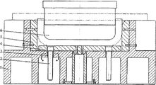
Fig. 1 is the utility model structural representation,
Fig. 2 is the A-A cutaway view of Fig. 1.
The specific embodiment
Below in conjunction with accompanying drawing, the utility model is further described by embodiment.
Referring to Fig. 1 and Fig. 2,
Hot pressure-shaped mould die pad guider, comprise that patrix 6, counterdie 1, counterdie insert 5 and die pad 4, on the length direction of die pad 4 bottom surfaces, be evenly equipped with two guide pillars 2, correspondingly with guide pillar 2 in counterdie, be provided with two guide pin bushings 3, two guide pillars 2 lay respectively in two guide pin bushings 3, and both cooperate;
Described guide pillar 2 is a cylinder, and is the plane in the both sides with the corresponding direction of die pad width, guide pillar 2 both sides plane parallel;
The described guide pin bushing corresponding with guide pillar 3 endoporus both sides are the plane;
Described guide pillar 2 and guide pin bushing 3 are matched in clearance on mating surface radical length direction.
This hot pressure-shaped mould die pad guider, in the operation of the U-shaped hot pressing part of strip, patrix 6 compresses the blank of heating downwards, the heat of blank directly passes to guide pillar 2 by die pad 4, make on the radical length direction of guide pillar 2 degrees of expansion greater than the degrees of expansion of guide pin bushing in the counterdie 3, but the design guide pillar of the matched in clearance that guide pillar 2 and guide pin bushing 3 relax on the radical length direction is worked up and down and can be obstructed, do not produce friction, the guide pillar 2 that is fixed on the die pad 4 can slide in guide pin bushing 3 smoothly.Guarantee to eject drip molding smoothly by die pad 4 behind the sheet material hot forming.Can also protect guide pillar to make it not produce infringement.
Claims (1)
1. hot pressure-shaped mould die pad guider, comprise that upper die and lower die, counterdie insert and die pad, on the length direction of die pad bottom surface, be laid with two guide pillars, correspondingly with guide pillar in counterdie, be provided with two guide pin bushings, two guide pillars cooperate respectively and are positioned at two guide pin bushings, it is characterized in that:
Described guide pillar is a cylinder, is the plane with the guide pillar both sides of the corresponding direction of die pad width, and the both sides plane parallel;
The described guide pin bushing endoporus both sides corresponding with guide pillar are the plane;
With cooperating between the corresponding guide pillars and bushes of die pad length direction be matched in clearance.
Priority Applications (1)
| Application Number | Priority Date | Filing Date | Title |
|---|---|---|---|
| CN2010202696236U CN201728789U (en) | 2010-07-21 | 2010-07-21 | Hot pressing die ejector plate guide device |
Applications Claiming Priority (1)
| Application Number | Priority Date | Filing Date | Title |
|---|---|---|---|
| CN2010202696236U CN201728789U (en) | 2010-07-21 | 2010-07-21 | Hot pressing die ejector plate guide device |
Publications (1)
| Publication Number | Publication Date |
|---|---|
| CN201728789U true CN201728789U (en) | 2011-02-02 |
Family
ID=43519949
Family Applications (1)
| Application Number | Title | Priority Date | Filing Date |
|---|---|---|---|
| CN2010202696236U Expired - Lifetime CN201728789U (en) | 2010-07-21 | 2010-07-21 | Hot pressing die ejector plate guide device |
Country Status (1)
| Country | Link |
|---|---|
| CN (1) | CN201728789U (en) |
Cited By (1)
| Publication number | Priority date | Publication date | Assignee | Title |
|---|---|---|---|---|
| CN107470557A (en) * | 2017-09-28 | 2017-12-15 | 张原彬 | A kind of big temperature difference working condition mould is guide locating device provided with chamfered edge guide pillar guide pin bushing |
-
2010
- 2010-07-21 CN CN2010202696236U patent/CN201728789U/en not_active Expired - Lifetime
Cited By (1)
| Publication number | Priority date | Publication date | Assignee | Title |
|---|---|---|---|---|
| CN107470557A (en) * | 2017-09-28 | 2017-12-15 | 张原彬 | A kind of big temperature difference working condition mould is guide locating device provided with chamfered edge guide pillar guide pin bushing |
Similar Documents
| Publication | Publication Date | Title |
|---|---|---|
| CN204278595U (en) | The anti-skidding material pressing device of a kind of heat pressing forming machines | |
| CN201728272U (en) | Combined die for punching plastic template steel frame | |
| CN203831838U (en) | Heating bedplate of hydraulic machine | |
| CN206474577U (en) | A kind of mould for turbine blade swaging | |
| CN203541420U (en) | Riveting machine | |
| CN202763922U (en) | Punching machine for forming of rubber sheets | |
| CN206633299U (en) | The friction plate hot pressing die of the chamber more than one piece of a multi-cavity mold one | |
| CN202080024U (en) | Semiautomatic stamping press | |
| CN204658833U (en) | A kind of mould of injection mo(u)lding vehicle noise insulation pad | |
| CN205522653U (en) | Brake block mould | |
| CN210940302U (en) | Core pulling mechanism | |
| CN202239095U (en) | Bending lower die | |
| CN211112930U (en) | Laptop White Wet Press Paper Molding Machine | |
| CN201537659U (en) | Quick Die Change Mechanism for Cold Stamping Machine Tool | |
| CN102729412B (en) | Mould used for thermosetting material | |
| CN203030753U (en) | Four-cylinder engine cylinder sealing sheet edge wrapping die | |
| CN209419422U (en) | A kind of double pressure head press-loading apparatus | |
| CN206464369U (en) | A kind of Plate Bending Machine | |
| CN224240465U (en) | Molding press | |
| CN204773195U (en) | Machinery mode locking device | |
| CN214645826U (en) | Processing tool for large rubber mold | |
| CN205798056U (en) | A kind of anchor ear processing unit (plant) | |
| CN204222370U (en) | A stamping machine | |
| CN202895400U (en) | Lockhole die for door seal edgings of wooden door | |
| CN213891426U (en) | Supplementary mold opening stroke device that increases of solid-state machine |
Legal Events
| Date | Code | Title | Description |
|---|---|---|---|
| C14 | Grant of patent or utility model | ||
| GR01 | Patent grant | ||
| CX01 | Expiry of patent term |
Granted publication date: 20110202 |
|
| CX01 | Expiry of patent term |