CN201702908U - Large-draft-angle reversed ejection and angle ejection demolding guide mechanism - Google Patents
Large-draft-angle reversed ejection and angle ejection demolding guide mechanism Download PDFInfo
- Publication number
- CN201702908U CN201702908U CN2010202255445U CN201020225544U CN201702908U CN 201702908 U CN201702908 U CN 201702908U CN 2010202255445 U CN2010202255445 U CN 2010202255445U CN 201020225544 U CN201020225544 U CN 201020225544U CN 201702908 U CN201702908 U CN 201702908U
- Authority
- CN
- China
- Prior art keywords
- guide
- angle
- slide block
- slider
- oblique top
- Prior art date
- Legal status (The legal status is an assumption and is not a legal conclusion. Google has not performed a legal analysis and makes no representation as to the accuracy of the status listed.)
- Expired - Fee Related
Links
- 230000007246 mechanism Effects 0.000 title claims abstract description 27
- 238000002347 injection Methods 0.000 abstract description 10
- 239000007924 injection Substances 0.000 abstract description 10
- 238000000465 moulding Methods 0.000 description 10
- 230000000694 effects Effects 0.000 description 4
- 238000010586 diagram Methods 0.000 description 3
- 239000010720 hydraulic oil Substances 0.000 description 3
- 238000001746 injection moulding Methods 0.000 description 3
- 239000003921 oil Substances 0.000 description 3
- 239000000243 solution Substances 0.000 description 2
- 238000001721 transfer moulding Methods 0.000 description 2
- 230000000295 complement effect Effects 0.000 description 1
- 238000005516 engineering process Methods 0.000 description 1
- 238000009434 installation Methods 0.000 description 1
- 238000012423 maintenance Methods 0.000 description 1
- 238000004519 manufacturing process Methods 0.000 description 1
- 239000000463 material Substances 0.000 description 1
- 238000000034 method Methods 0.000 description 1
- 230000007659 motor function Effects 0.000 description 1
- 239000004033 plastic Substances 0.000 description 1
- 229920003023 plastic Polymers 0.000 description 1
- 239000000725 suspension Substances 0.000 description 1
Images



Landscapes
- Moulds For Moulding Plastics Or The Like (AREA)
Abstract
The utility model relates to the technical field of injection molds, in particular to a large-draft-angle reversed ejection and angle ejection demolding guide mechanism, which solves the problems that the inner wall face of an injection molded product has larger draft angle, and no sufficient space inside the product is provided for disposing other mechanism. The guide mechanism comprises a lower fixing board, an ejector plate and a guide rod, wherein a slider guide block is arranged on the lower fixing board, a slider seat is arranged on the ejector plate, the slider guide block is provided with a dip angle from bottom to top in the length direction, while a guide rail is arranged in the length direction of the slider guide block, a skewed slot is arranged on the slider seat, a slider matched with the skewed slot is installed inside the skewed slot, and a chute matched with the guide rail is arranged on one side of the slider towards the slider guide block, the slider guide block is fixed onto the lower fixing board, the ejector plate pushes the slider on the slider seat to move along the slider guide block, the upper end of the guide rod is connected with an angle ejection formed head, and a movement angle formed by the slider guide block, the slider and the guide rod is set according to the direction of product demolding, thereby realizing normal movement function of an angle ejection demolding mechanism.
Description
Technical field
The utility model relates to the injection mould technical field, especially relates to the back-off that a kind of injecting products inwall has big demoulding angle, and can only oppositely eject the oblique top guiding mechanism with the loose core big draft angle of demoulding occasion of oblique top mode.
Background technology
Oblique top in the injection mould is simple in structure because of it, and requisite space is little, becomes core-pulling mechanism common in the mould of plastics industry.In the general mould structure; the back-off mould emptier of product inwall is taked oblique top or inner core pulling scheme mostly; back-off to the existence of product inside; product inside must have enough spaces to design oblique top mechanism; and demoulding angle is unsuitable excessive; generally be no more than 30 degree, and at the demoulding angle of product inwall back-off at 39 degree, common oblique top mechanism can't realize product stripping.Demoulding angle greater than the oblique tops of 30 degree can't regular event main cause mainly be in the oblique top motion process self-locking to take place and lost efficacy.Ejecting mechanism in the injection mold is various informative, and the guiding mechanism structure is changeable equally, but all is to design by needed technological requirement in products characteristics and the manufacturing process.As the Chinese patent publication number is 201,120,703 1 kinds of injection mold inclined push type mould emptiers; it is provided with on the die of back and is parallel to horizontal top slideway that ejects direction and the oblique top slideway that guides an oblique top demoulding; one end of transverse crown bar crosses the oblique top head and is formed with the slide rail that is complementary with horizontal top slideway; slide block is inserted and is fixed on the other end of transverse crown bar; the oblique top head can be slidingly connected on push rod along the direction of motion perpendicular to ejecting direction of oblique top head; this structure is when the demoulding; transverse crown bar can promote the slide block relative oblique top head of inserting and do level and slide left, makes the back-off structure of goods break away from the oblique top head.And for example patent publication No. is the demoulding liftout attachment of a CN1966239 injection transfer molding machine, be fixed on the board below of injection transfer molding machine and be positioned at the fixed head that the demoulding ejects the position by one group of suspension rod, the cope match-plate pattern that is held up hydraulic oil cylinder driving by two cope match-plate patterns holds up mechanism, the middle template of two middle template picking-up hydraulic oil cylinder driving holds up mechanism, an injection moulding spare ejects the injection moulding spare ejecting mechanism of hydraulic oil cylinder driving, cope match-plate pattern holds up oil cylinder, middle template holds up oil cylinder and injection moulding spare, ejecting oil cylinder is fixedly mounted on the lower surface of fixed head, adopt this demoulding liftout attachment, in order to remove the superfluous material on the cope match-plate pattern plane.
Summary of the invention
The purpose of this utility model is in order to solve the injecting products internal face big demoulding angle to be arranged; product inside does not have enough spaces that other mechanisms are set; adopt the big demoulding angle of injection mould oppositely to eject the external guiding problem of oblique top mould emptier; a kind of reasonable in design is provided; increase external guidance system to oblique top; adopt a plurality of each working cell direction of motion to move by different angles by demoulding requirement design; cooperatively interact; the motion of oblique top mould emptier was no longer lost efficacy because angle is excessive, and the big draft angle of efficient stable oppositely ejects oblique top demoulding guiding mechanism.
Above-mentioned technical problem of the present utility model is mainly solved by following technical proposals: a kind of big draft angle oppositely ejects oblique top demoulding guiding mechanism, comprise bottom plate, end needle plate, guide post, it is characterized in that described bottom plate is provided with SLIDE GUIDE, end needle plate is provided with the slide block base, the SLIDE GUIDE length direction has the inclination angle from bottom to top and is provided with guide rail at its length direction, the slide block base is provided with skewed slot, the slide block that cooperates with skewed slot is housed in the skewed slot, and slide block is provided with the chute that cooperates with guide rail towards a side of SLIDE GUIDE.SLIDE GUIDE is fixed on the bottom plate; the slide block that end needle plate promotes on the slide block base moves along SLIDE GUIDE; the upper end of guide post is to link to each other with oblique top moulding head; the movement angle that SLIDE GUIDE, slide block, guide post are formed is pressed the direction setting of product stripping, realizes the normal motor function of oblique top mould emptier.
The oblique top mould emptier of injection mould is a kind of big demoulding angle; how making big demoulding angle oblique top motion smooth and easy is the subject matter that needs solution; and product inwall back-off demoulding angle is higher than the extreme angles of oblique top mould emptier motion; it is the regular event that is unfavorable for conventional oblique top mould emptier; adopt oblique top mould emptier base to carry additionally the measure of external guiding mechanism, can solve the problem that causes mechanism kinematic to lose efficacy because of lacking.
As preferably, the guide rail that described SLIDE GUIDE is provided with size up and down equates that the inclination angle that has is formed by track base from bottom to top, and guide rail is T type or dove-tail form.SLIDE GUIDE vertically is installed on the bottom plate, and the motion oblique angle of slide block realized by the oblique angle of SLIDE GUIDE, and the oblique angle of SLIDE GUIDE is by the movement angle decision of oblique top mould emptier.
As preferably, the lower end of described SLIDE GUIDE is provided with down locating wedge, and the upper end is provided with locating wedge, and following locating wedge is positioned on the bottom plate, and the Template Location in last locating wedge and the mold is also fixing.Locating wedge is mainly used in the location up and down, and the structure that SLIDE GUIDE and bottom plate and male model plate are formed is stronger, also can adopt modes such as key connecting, flange connection, Bolt Connection.
As preferably, the face that described slide block cooperates with the slide block base is provided with oblique rail, and slide block cooperates with the skewed slot of slide block base for T type groove structure or oat tail groove structure cooperate, and tiltedly rail becomes the angle of spending greater than 50 with chute.The track that oblique rail can provide level and vertical both direction to move simultaneously, the demoulding angle of big demoulding angle inwall back-off reach 39 degree, and external guide rail structure has satisfied this needs fully.
As preferably, described slide block is provided with the plane, is provided with several staged through holes in the last plane, and the staged through hole passes slide body and passes from the plane at oblique rail place, and the staged through hole is connected with an end of guide post.The staged through hole on plane is used for fixing guide post on the slide block, and guide post promotes the oblique top moulding headwork of mould, is provided with the rank, hole in the hole of staged through hole, and hexagon socket head cap screw is penetrated installation from the plane at oblique rail place.
Effective effect of the present utility model is: make the injecting products internal face that the back-off of big demoulding angle be arranged, and can only loose core the product of the demoulding in knockout course with the oblique top mode, shared stroke obstacle greatly, made big draft angle oppositely eject the oblique top demoulding and realize smoothly.
Therefore, the utility model is a kind of reasonable in design, moves highly sensitive, easy to maintenance, practical big draft angle and oppositely ejects oblique top demoulding guiding mechanism.
Description of drawings
Fig. 1 is a kind of structural representation of the present utility model.
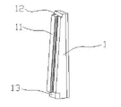
Fig. 2 is a kind of SLIDE GUIDE structural representation of the present utility model.
Fig. 3 is a kind of slide block structure schematic diagram of the present utility model.
Fig. 4 is the plan structure schematic diagram of the utility model Fig. 3.
Fig. 5 is a kind of slide block understructure schematic diagram of the present utility model.
Among the figure: 1. SLIDE GUIDE, 11. guide rails, locating wedge on 12., 13. times locating wedges, 2. guide post, 3. slide block, 31. staged through holes, 32. chutes, 33. oblique rails, 4. slide block base, 41. skewed slots, 5. bottom plate, 6. end needle plate.
The specific embodiment
Below by embodiment, and in conjunction with the accompanying drawings, the technical solution of the utility model is described in further detail.
Referring to Fig. 1, a kind of big draft angle of present embodiment oppositely ejects oblique top demoulding guiding mechanism, be provided with SLIDE GUIDE 1, SLIDE GUIDE 1 is fixed on the bottom plate 5, and SLIDE GUIDE 1 one sides are provided with guide rail 11, above SLIDE GUIDE 1, be provided with end needle plate 6, fix a slide block base 4 on the end needle plate 6, slide block base 4 is provided with skewed slot 41, referring to Fig. 5, the slide block 3 that cooperates with skewed slot 41 is housed in the skewed slot 41, two guide posts 2 are housed on the slide block 3.
As shown in Figure 2, SLIDE GUIDE 1 length direction has the inclination angle from bottom to top and is provided with T type guide rail 11 along its length, guide rail about in the of 11 size equate that the inclination angle that has is to be formed by track base from bottom to top.The lower end of SLIDE GUIDE 1 is provided with the following locating wedge 13 with a step, and the upper end is provided with the last locating wedge 12 with a step, and following locating wedge 13 cooperates with bottom plate 5 and is fixed on the bottom plate 5, and last locating wedge 12 is also fixing with the Template Location in the mold.
Referring to Fig. 3, Fig. 4, the face that slide block 3 cooperates with slide block base 4 is provided with the oblique rail 33 of T type structure, tiltedly skewed slot 41 matched in clearance of the T type structure of rail 33 and slide block base 4, the tiltedly angles of 32 one-tenth 51 degree of rail 33 and chute.Slide block 3 tops are plane on, be provided with two staged through holes 31 in the last plane, two staged through holes 31 all pass slide block 3 bodies and pass from the plane at oblique rail 33 places, carry out spot-facing from the plane at oblique rail 33 places, be used for assembling soket head cap screw, an end of guide post 2 is provided with screw and is fixed in the staged through hole 31.
By the end needle plate 6 in the ejection system promotion mold of molding machine, the oblique top molding structure moves upward, the slide block 3 of oblique top molding structure below is under the effect of SLIDE GUIDE 1, chute 41 guiding angle directions along slide block base 4 move, SLIDE GUIDE 1 is fixed on bottom plate 5 and keeps motionless, and the oblique top molding structure is loosed core along product back-off stripping direction.
Mold resets under the effect of back-moving spring, the oblique top molding structure is under the driving of liftout plate, whole oblique top molding structure begins action, slide block 3 is under SLIDE GUIDE 1 effect, guide chute 41 along slide block base 4 moves, the oblique top molding structure moves down gradually, resets fully until whole oblique top molding structure.
Claims (5)
1. a big draft angle oppositely ejects oblique top demoulding guiding mechanism, comprise bottom plate (5), end needle plate (6), guide post (2), it is characterized in that described bottom plate (5) is provided with SLIDE GUIDE (1), end needle plate (6) is provided with slide block base (4), SLIDE GUIDE (1) length direction has the inclination angle from bottom to top and is provided with guide rail (11) at its length direction, slide block base (4) is provided with skewed slot (41), the slide block (3) that cooperates with skewed slot is housed in the skewed slot (41), and slide block (3) is provided with the chute (32) that cooperates with guide rail (11) towards a side of SLIDE GUIDE (1).
2. big draft angle according to claim 1 oppositely ejects oblique top demoulding guiding mechanism, it is characterized in that guide rail (11) that described SLIDE GUIDE (1) is provided with up and down size equate, the inclination angle that has is from bottom to top formed by track base, and guide rail (11) is T type or dove-tail form.
3. big draft angle according to claim 1 and 2 oppositely ejects oblique top demoulding guiding mechanism, the lower end that it is characterized in that described SLIDE GUIDE (1) is provided with down locating wedge (13), the upper end is provided with locating wedge (12), following locating wedge (13) is positioned on the bottom plate (5), and last locating wedge (12) is also fixing with the Template Location in the mold.
4. big draft angle according to claim 1 oppositely ejects oblique top demoulding guiding mechanism, it is characterized in that the face that described slide block (3) cooperates with slide block base (4) is provided with oblique rail (33), it is that T type groove structure or oat tail groove structure cooperate that slide block (3) cooperates with the skewed slot (41) of slide block base (4), and tiltedly rail (33) becomes the angle greater than 50 degree with chute (32).
5. oppositely eject oblique top demoulding guiding mechanism according to claim 1 or 4 described big draft angles, it is characterized in that described slide block (3) is provided with the plane, be provided with several staged through holes (31) in the last plane, staged through hole (31) passes slide block (3) body and passes from the plane at oblique rail (33) place, and staged through hole (31) is connected with an end of guide post (2).
Priority Applications (1)
| Application Number | Priority Date | Filing Date | Title |
|---|---|---|---|
| CN2010202255445U CN201702908U (en) | 2010-06-13 | 2010-06-13 | Large-draft-angle reversed ejection and angle ejection demolding guide mechanism |
Applications Claiming Priority (1)
| Application Number | Priority Date | Filing Date | Title |
|---|---|---|---|
| CN2010202255445U CN201702908U (en) | 2010-06-13 | 2010-06-13 | Large-draft-angle reversed ejection and angle ejection demolding guide mechanism |
Publications (1)
| Publication Number | Publication Date |
|---|---|
| CN201702908U true CN201702908U (en) | 2011-01-12 |
Family
ID=43440058
Family Applications (1)
| Application Number | Title | Priority Date | Filing Date |
|---|---|---|---|
| CN2010202255445U Expired - Fee Related CN201702908U (en) | 2010-06-13 | 2010-06-13 | Large-draft-angle reversed ejection and angle ejection demolding guide mechanism |
Country Status (1)
| Country | Link |
|---|---|
| CN (1) | CN201702908U (en) |
Cited By (6)
| Publication number | Priority date | Publication date | Assignee | Title |
|---|---|---|---|---|
| CN103847044A (en) * | 2012-11-29 | 2014-06-11 | 汉达精密电子(昆山)有限公司 | Wide-angle oblique pin structure of mold |
| CN104772873A (en) * | 2015-04-03 | 2015-07-15 | 重庆长安汽车股份有限公司 | Submarine side gate slanted ejector rubber feeding mechanism for automobile injection molds |
| CN108407227A (en) * | 2018-03-14 | 2018-08-17 | 江苏星科精密模具有限公司 | A kind of high-mount stop lamp mold and injection molding machine and its working method |
| CN109130110A (en) * | 2018-07-26 | 2019-01-04 | 杜弗尼工程机械(苏州)有限公司 | A kind of oblique top of the big shift motion of plastic mold wide-angle |
| CN110328816A (en) * | 2019-08-12 | 2019-10-15 | 华域视觉科技(上海)有限公司 | A kind of reverse buckle demolding mechanism and injection mold |
| CN115157580A (en) * | 2022-07-26 | 2022-10-11 | 歌尔科技有限公司 | Demoulding mechanism and injection mold |
-
2010
- 2010-06-13 CN CN2010202255445U patent/CN201702908U/en not_active Expired - Fee Related
Cited By (9)
| Publication number | Priority date | Publication date | Assignee | Title |
|---|---|---|---|---|
| CN103847044A (en) * | 2012-11-29 | 2014-06-11 | 汉达精密电子(昆山)有限公司 | Wide-angle oblique pin structure of mold |
| CN103847044B (en) * | 2012-11-29 | 2016-11-23 | 汉达精密电子(昆山)有限公司 | The large-angle inclined latch structure of mould |
| CN104772873A (en) * | 2015-04-03 | 2015-07-15 | 重庆长安汽车股份有限公司 | Submarine side gate slanted ejector rubber feeding mechanism for automobile injection molds |
| CN108407227A (en) * | 2018-03-14 | 2018-08-17 | 江苏星科精密模具有限公司 | A kind of high-mount stop lamp mold and injection molding machine and its working method |
| CN108407227B (en) * | 2018-03-14 | 2024-03-12 | 江苏星科精密模具有限公司 | High-mounted brake lamp mold, injection molding machine and working method of injection molding machine |
| CN109130110A (en) * | 2018-07-26 | 2019-01-04 | 杜弗尼工程机械(苏州)有限公司 | A kind of oblique top of the big shift motion of plastic mold wide-angle |
| CN110328816A (en) * | 2019-08-12 | 2019-10-15 | 华域视觉科技(上海)有限公司 | A kind of reverse buckle demolding mechanism and injection mold |
| CN115157580A (en) * | 2022-07-26 | 2022-10-11 | 歌尔科技有限公司 | Demoulding mechanism and injection mold |
| CN115157580B (en) * | 2022-07-26 | 2024-02-09 | 歌尔科技有限公司 | Demoulding mechanism and injection mould |
Similar Documents
| Publication | Publication Date | Title |
|---|---|---|
| CN110757744B (en) | Injection mold with back mold integral section back-off demolding structure | |
| CN101973111B (en) | Large demoulding angle and reverse ejection pitched roof mold emptier for injection mold | |
| CN201371561Y (en) | Injection mold and secondary ejector mechanism thereof | |
| CN201120684Y (en) | Mold ejection mechanism and mold including the ejection mechanism | |
| CN202742634U (en) | Complete cycle barb demoulding mechanism | |
| CN201268073Y (en) | Ejecting mechanism for preventing mould oblique jacking guide bar interference | |
| CN203357823U (en) | Ejection structure of mold | |
| CN219028340U (en) | Mould with inclined hole core-pulling mechanism | |
| CN216683211U (en) | Oblique ejection mechanism of injection mold | |
| CN114434757B (en) | A mould for drawing of patterns of wide-angle back-off | |
| CN214353894U (en) | Injection mold for producing automotive upholstery | |
| CN202702536U (en) | Injection mould small push rod secondary ejection mechanism | |
| CN211640835U (en) | Ejecting mechanism in slider | |
| CN211807592U (en) | Remote controller upper cover catching groove pushes up demoulding mechanism to one side | |
| CN201863367U (en) | Mechanical type secondary ejection mold | |
| CN219133055U (en) | Plastic cover plate injection mold | |
| CN223456424U (en) | Anti-deformation mechanism for inclined ejector rod in injection mold | |
| CN220808368U (en) | Inclined top anti-sticking mechanism for demolding | |
| CN220883188U (en) | Door plant gadget injection mold | |
| CN218701014U (en) | Mold ejection structure | |
| CN218139701U (en) | Slide thimble device | |
| CN224197244U (en) | Product mould | |
| CN223834956U (en) | Elastic demolding and resetting structure of TPE (thermoplastic elastomer) automobile trunk pad injection molding die | |
| CN213321422U (en) | External ejection early-resetting structure for ensuring safety production of injection mold | |
| CN220314040U (en) | Core pulling reversing mechanism |
Legal Events
| Date | Code | Title | Description |
|---|---|---|---|
| C14 | Grant of patent or utility model | ||
| GR01 | Patent grant | ||
| C56 | Change in the name or address of the patentee | ||
| CP01 | Change in the name or title of a patent holder |
Address after: 315400, No. 518, Shun Shun Road, Yuyao, Zhejiang, Ningbo Patentee after: NINGBO SUNNY MOULD CO., LTD. Address before: 315400, No. 518, Shun Shun Road, Yuyao, Zhejiang, Ningbo Patentee before: Ningbo Sunny Mould Co., Ltd. |
|
| CF01 | Termination of patent right due to non-payment of annual fee |
Granted publication date: 20110112 Termination date: 20160613 |
|
| CF01 | Termination of patent right due to non-payment of annual fee |