CN201702366U - Combined mould - Google Patents
Combined mould Download PDFInfo
- Publication number
- CN201702366U CN201702366U CN2010201770133U CN201020177013U CN201702366U CN 201702366 U CN201702366 U CN 201702366U CN 2010201770133 U CN2010201770133 U CN 2010201770133U CN 201020177013 U CN201020177013 U CN 201020177013U CN 201702366 U CN201702366 U CN 201702366U
- Authority
- CN
- China
- Prior art keywords
- plate
- lower roof
- backboard
- top board
- polylith
- Prior art date
- Legal status (The legal status is an assumption and is not a legal conclusion. Google has not performed a legal analysis and makes no representation as to the accuracy of the status listed.)
- Expired - Fee Related
Links
- 208000002925 dental caries Diseases 0.000 claims description 7
- 238000004519 manufacturing process Methods 0.000 abstract description 6
- 239000000696 magnetic material Substances 0.000 description 3
- 230000002950 deficient Effects 0.000 description 2
- 238000000465 moulding Methods 0.000 description 2
- 230000009286 beneficial effect Effects 0.000 description 1
- 238000010586 diagram Methods 0.000 description 1
- 238000005516 engineering process Methods 0.000 description 1
Images
Landscapes
- Press-Shaping Or Shaping Using Conveyers (AREA)
Abstract
The utility model discloses a combined mould, which comprises an upper pressing plate (1), a left side plate (2), a right side plate (3), a front baffle (4), a back baffle (5) and a lower roof (6). The left side plate (2), the right side plate (3), the front baffle (4) and the back baffle (5) are connected into a rectangle. The combined mould also comprises at least one separating plate (7) which is parallel to the front baffle (4) and the back baffle (5) and is connected to the left side plate (2) and the right side plate (3); the number of the upper pressing plate (1) is more than one; the number of the left side plate (2) is more than one; the size and shape of horizontal cross section of the upper pressing plate (1) and the lower roof (6) are matched with the size and shape of a plurality of cavities (10); and the number of the upper pressing plate (1) and the left side plate (2) are equal to the number of the cavities (10). The combined mould is time-saving, labor-saving and high in production efficiency.
Description
Technical field
The utility model relates to a kind of assembling die, specifically is a kind of assembling die that is used for the magnetic material moulding.
Background technology
At present, the moulding of China's magnetic material is mainly undertaken by the fixed combination mould, and this assembling die comprises top board, left plate, right plate, front apron, backboard and lower roof plate, and described top board is connected with the drift of hydraulic press; Described left plate, right plate, front apron, backboard join and surround rectangle; Described lower roof plate is connected with the push rod of hydraulic press.There is following defective in the assembling die of said structure in the production process of reality:
1, because the existing fixed assembling die can only be produced a magnetic block in a complete process-cycle, so the production efficiency of this mould is lower.
2, because the purposes of magnetic material is very extensive, therefore the concrete specification of making magnetic block is also varied, and because existing assembling die once can only be produced a kind of magnetic block of specification, the magnetic block of producing other specification then needs to stop, mold exchange, drive, therefore the use of this mould is not only wasted time and energy, and production efficiency is low.
The utility model content
The technical problems to be solved in the utility model is, overcomes the defective of above prior art, provides a kind of and saves time, laborsaving and assembling die that production efficiency is high.
The technical solution of the utility model is, a kind of assembling die is provided, comprise top board, left plate, right plate, front apron, backboard and lower roof plate, described left plate, right plate, front apron, backboard join and surround rectangle, it also comprises at least one dividing plate, and described dividing plate and front apron, backboard are parallel; Described dividing plate is connected with left plate, right plate respectively; Described dividing plate and left plate, right plate, front apron, backboard form a plurality of cavitys; Described top board is a polylith; Described lower roof plate is a polylith; The size shape of the size shape of the horizontal cross-section of described polylith top board and polylith lower roof plate and the horizontal cross-section of a plurality of cavitys matches one by one; The quantity of described top board equates with the quantity of cavity respectively with the quantity of lower roof plate.
After adopting above structure, the utility model compared with prior art has the following advantages:
Be provided with the polylith dividing plate in the utility model assembling die, it can be divided into a plurality of inner chambers with an inner chamber of mould, in a complete course of action, promptly can make the magnetic block that the polylith specification is identical or specification is different like this, therefore the use of the utility model assembling die is not only time saving and energy saving, and the production efficiency height.
As improvement, the size dimension of described a plurality of cavitys is inequality, so the utility model especially is beneficial to the magnetic block of producing multiple different size simultaneously, thereby more time saving and energy saving, is more conducive to enhance productivity.
Description of drawings
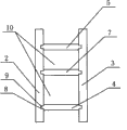
Fig. 1 is the structural representation of the utility model assembling die.
Fig. 2 is the fragmentary top TV structure schematic diagram of the utility model assembling die.
Shown in the figure 1, top board, 2, left plate, 3, right plate, 4, front apron, 5, backboard, 6, lower roof plate, 7, dividing plate, 8, groove, 9, projection, 10, cavity.
The specific embodiment
The utility model is described in further detail below in conjunction with the drawings and specific embodiments.
As Fig. 1, Fig. 2, shown in Figure 3, a kind of assembling die of the utility model, comprise top board 1, left plate 2, right plate 3, front apron 4, backboard 5 and lower roof plate 6, described left plate 2, right plate 3, front apron 4, backboard 5 join and surround rectangle, and promptly front apron 4, backboard 5 are plugged in left plate 2 and the right plate 3.
Described assembling die also comprises at least one dividing plate 7, and described dividing plate 7 and front apron 4, backboard 5 are parallel; Described dividing plate 7 is connected with left plate 2, right plate 3 respectively, and an end of promptly described dividing plate 7 is connected with left plate 2, and the other end of described dividing plate 7 is connected with right plate 3.
Described dividing plate 7 forms a plurality of cavitys 10 with left plate 2, right plate 3, front apron 4, backboard 5.
Described top board 1 is a polylith, and described polylith top board 1 is connected (not shown) with a plurality of drifts of hydraulic press respectively; Described lower roof plate 2 is a polylith, and described polylith lower roof plate 2 is connected (not shown) with a plurality of push rods of hydraulic press respectively.
The size shape of the size shape of the horizontal cross-section of described polylith top board 1 and polylith lower roof plate 6 and the horizontal cross-section of a plurality of cavity 10 matches one by one; The quantity of described top board 1 equates with the quantity of cavity 10 respectively with the quantity of lower roof plate 2.
Described left plate 2 is provided with at least one pair of equal and opposite in direction and position groove opposite 8 with the opposite side of right plate 3, and described dividing plate 7 is provided with the projection 9 that at least one pair of and groove 8 size shape match, and described projection 9 is embedded in the groove 8.Be that dividing plate 7 is pegged graft with left plate 2, right plate 3 respectively.
The size dimension of described a plurality of cavity 10 is inequality, and the specification of the magnetic block of promptly producing is different.
In the present embodiment, dividing plate 7 is one, and it can form two cavitys 10, and the quantity of the top board 1 of Pei Heing is 2 with it, and the quantity of lower roof plate 6 is 2.And dividing plate 7 is inconsistent with the distance of front apron 4, backboard 5.
The quantity of the utility model median septum 7 can be 3,4,5,6 etc., and its cavity 10 that forms relatively is 4,5,6,7 etc., and the quantity of the top board 1 that is used with it can be 4,5,6,7, and the quantity of lower roof plate 6 is 4,5,6,7 etc.; These are all in protection domain of the present utility model.
Claims (3)
1. assembling die, comprise top board (1), left plate (2), right plate (3), front apron (4), backboard (5) and lower roof plate (6), described left plate (2), right plate (3), front apron (4), backboard (5) join and surround rectangle, it is characterized in that: it also comprises at least one dividing plate (7), and described dividing plate (7) and front apron (4), backboard (5) are parallel; Described dividing plate (7) is connected with left plate (2), right plate (3) respectively; Described dividing plate (7) forms a plurality of cavitys (10) with left plate (2), right plate (3), front apron (4), backboard (5); Described top board (1) is a polylith; Described lower roof plate (2) is a polylith; The size shape of the horizontal cross-section of the size shape of the horizontal cross-section of described polylith top board (1) and polylith lower roof plate (6) and a plurality of cavity (10) matches one by one; The quantity of described top board (1) equates with the quantity of cavity (10) respectively with the quantity of lower roof plate (2).
2. assembling die according to claim 1, it is characterized in that: described left plate (2) is provided with at least one pair of equal and opposite in direction and position groove opposite (8) with the opposite side of right plate (3), described dividing plate (7) is provided with the projection (9) that at least one pair of and groove (8) size shape match, and described projection (9) is embedded in the groove (8).
3. assembling die according to claim 1 is characterized in that: the size dimension of described a plurality of cavitys (10) is inequality.
Priority Applications (1)
| Application Number | Priority Date | Filing Date | Title |
|---|---|---|---|
| CN2010201770133U CN201702366U (en) | 2010-04-27 | 2010-04-27 | Combined mould |
Applications Claiming Priority (1)
| Application Number | Priority Date | Filing Date | Title |
|---|---|---|---|
| CN2010201770133U CN201702366U (en) | 2010-04-27 | 2010-04-27 | Combined mould |
Publications (1)
| Publication Number | Publication Date |
|---|---|
| CN201702366U true CN201702366U (en) | 2011-01-12 |
Family
ID=43439514
Family Applications (1)
| Application Number | Title | Priority Date | Filing Date |
|---|---|---|---|
| CN2010201770133U Expired - Fee Related CN201702366U (en) | 2010-04-27 | 2010-04-27 | Combined mould |
Country Status (1)
| Country | Link |
|---|---|
| CN (1) | CN201702366U (en) |
Cited By (9)
| Publication number | Priority date | Publication date | Assignee | Title |
|---|---|---|---|---|
| CN102198474A (en) * | 2011-04-22 | 2011-09-28 | 昆山长鹰硬质合金有限公司 | Die for producing long lath |
| CN102248075A (en) * | 2011-06-10 | 2011-11-23 | 昆山长鹰硬质合金有限公司 | Punching die of long lath |
| CN102274891A (en) * | 2011-06-10 | 2011-12-14 | 昆山长鹰硬质合金有限公司 | Mould for producing hard alloy long strip |
| CN102350608A (en) * | 2011-09-21 | 2012-02-15 | 岳阳大力神电磁机械有限公司 | Welding fixture and welding process for magnetic medium box |
| CN104923661A (en) * | 2014-03-19 | 2015-09-23 | 福特全球技术公司 | Composite dies and method of making the same |
| CN105880587A (en) * | 2016-05-13 | 2016-08-24 | 内蒙古科元胜力金山稀土科技有限公司 | Perpendicular pressing and forming mould for slices |
| CN106493360A (en) * | 2016-12-14 | 2017-03-15 | 京磁材料科技股份有限公司 | The compacting tool set of neodymium iron boron magnetic body |
| CN107854096A (en) * | 2017-12-12 | 2018-03-30 | 芜湖广盈实业有限公司 | A kind of drawer dishwasher inner bag and its moulding process |
| CN108097960A (en) * | 2018-01-30 | 2018-06-01 | 河南涵信金刚石工具有限公司 | A kind of small dimension carves saw blade hot pressing die |
-
2010
- 2010-04-27 CN CN2010201770133U patent/CN201702366U/en not_active Expired - Fee Related
Cited By (13)
| Publication number | Priority date | Publication date | Assignee | Title |
|---|---|---|---|---|
| CN102198474A (en) * | 2011-04-22 | 2011-09-28 | 昆山长鹰硬质合金有限公司 | Die for producing long lath |
| CN102248075A (en) * | 2011-06-10 | 2011-11-23 | 昆山长鹰硬质合金有限公司 | Punching die of long lath |
| CN102274891A (en) * | 2011-06-10 | 2011-12-14 | 昆山长鹰硬质合金有限公司 | Mould for producing hard alloy long strip |
| CN102350608A (en) * | 2011-09-21 | 2012-02-15 | 岳阳大力神电磁机械有限公司 | Welding fixture and welding process for magnetic medium box |
| CN102350608B (en) * | 2011-09-21 | 2014-05-21 | 岳阳大力神电磁机械有限公司 | Welding fixture and welding process for magnetic medium box |
| CN104923661B (en) * | 2014-03-19 | 2019-10-18 | 福特全球技术公司 | Composable mold and its manufacturing method |
| CN104923661A (en) * | 2014-03-19 | 2015-09-23 | 福特全球技术公司 | Composite dies and method of making the same |
| CN105880587A (en) * | 2016-05-13 | 2016-08-24 | 内蒙古科元胜力金山稀土科技有限公司 | Perpendicular pressing and forming mould for slices |
| CN105880587B (en) * | 2016-05-13 | 2019-06-07 | 生一伦磁业有限公司 | A kind of vertical press-moulding die of thin slice |
| CN106493360B (en) * | 2016-12-14 | 2018-12-07 | 京磁材料科技股份有限公司 | The compacting tool set of neodymium iron boron magnetic body |
| CN106493360A (en) * | 2016-12-14 | 2017-03-15 | 京磁材料科技股份有限公司 | The compacting tool set of neodymium iron boron magnetic body |
| CN107854096A (en) * | 2017-12-12 | 2018-03-30 | 芜湖广盈实业有限公司 | A kind of drawer dishwasher inner bag and its moulding process |
| CN108097960A (en) * | 2018-01-30 | 2018-06-01 | 河南涵信金刚石工具有限公司 | A kind of small dimension carves saw blade hot pressing die |
Similar Documents
| Publication | Publication Date | Title |
|---|---|---|
| CN202539565U (en) | Adjustable die | |
| CN203957077U (en) | A kind of plug-in standard brick mould | |
| CN203622617U (en) | Semi-circular-arc ridge tile forming mold | |
| CN202079281U (en) | Rectangular die for neodymium-iron-boron materials | |
| CN203381107U (en) | Novel injection mold | |
| CN202943871U (en) | Core pulling device of vacuum plastic suction molding mould of refrigerator door liner | |
| CN201423729Y (en) | Silicone membrane producing die | |
| CN202411415U (en) | Magnetic material pressing die | |
| CN104552558A (en) | Thin-wall concrete hollow shell forming machine | |
| CN203391202U (en) | Common mould frame | |
| CN202087687U (en) | Bent pipe forming die | |
| CN201736317U (en) | Combined die for producing air brick safety device | |
| CN202826267U (en) | Injection mold structure of backlight source light guide plate | |
| CN204545333U (en) | A kind of bipolar half rounds electroslag rod die | |
| CN205889653U (en) | Novel forming die for rubber synthesis convenient to combination | |
| CN203331443U (en) | Pet food pressing die | |
| CN201669852U (en) | Bend mould | |
| CN202943794U (en) | Core-pulling mechanism of vacuum molding mold of refrigerator inner container | |
| CN202572840U (en) | Injection molding die for front supporting pad of engine | |
| CN202079280U (en) | Round die for neodymium-iron-boron materials | |
| CN203527737U (en) | Pouring device on forming mould | |
| CN203830701U (en) | Diagonal rod piston machining die | |
| CN202293199U (en) | Bicolor injection mold for spinning | |
| CN207735589U (en) | An Improved Magnetic Material Mold | |
| CN203184353U (en) | Novel upper collecting tube forming die structure |
Legal Events
| Date | Code | Title | Description |
|---|---|---|---|
| C14 | Grant of patent or utility model | ||
| GR01 | Patent grant | ||
| C17 | Cessation of patent right | ||
| CF01 | Termination of patent right due to non-payment of annual fee |
Granted publication date: 20110112 Termination date: 20140427 |