CN201701658U - Tall building escape self rescue device - Google Patents
Tall building escape self rescue device Download PDFInfo
- Publication number
- CN201701658U CN201701658U CN2010202025176U CN201020202517U CN201701658U CN 201701658 U CN201701658 U CN 201701658U CN 2010202025176 U CN2010202025176 U CN 2010202025176U CN 201020202517 U CN201020202517 U CN 201020202517U CN 201701658 U CN201701658 U CN 201701658U
- Authority
- CN
- China
- Prior art keywords
- fixed
- main shaft
- countershaft
- window
- life saving
- Prior art date
- Legal status (The legal status is an assumption and is not a legal conclusion. Google has not performed a legal analysis and makes no representation as to the accuracy of the status listed.)
- Expired - Fee Related
Links
- 230000007246 mechanism Effects 0.000 claims abstract description 41
- 230000000979 retarding effect Effects 0.000 claims description 12
- 238000004804 winding Methods 0.000 abstract 11
- 239000003638 chemical reducing agent Substances 0.000 abstract 2
- 230000000087 stabilizing effect Effects 0.000 abstract 2
- 230000000694 effects Effects 0.000 description 4
- 238000000034 method Methods 0.000 description 4
- 230000008569 process Effects 0.000 description 4
- 230000007423 decrease Effects 0.000 description 3
- 239000006096 absorbing agent Substances 0.000 description 2
- 230000005484 gravity Effects 0.000 description 2
- 238000012986 modification Methods 0.000 description 2
- 230000004048 modification Effects 0.000 description 2
- 239000007787 solid Substances 0.000 description 2
- UGFAIRIUMAVXCW-UHFFFAOYSA-N Carbon monoxide Chemical compound [O+]#[C-] UGFAIRIUMAVXCW-UHFFFAOYSA-N 0.000 description 1
- 230000001133 acceleration Effects 0.000 description 1
- 230000009286 beneficial effect Effects 0.000 description 1
- 238000006243 chemical reaction Methods 0.000 description 1
- 230000008878 coupling Effects 0.000 description 1
- 238000010168 coupling process Methods 0.000 description 1
- 238000005859 coupling reaction Methods 0.000 description 1
- 230000007547 defect Effects 0.000 description 1
- 230000007812 deficiency Effects 0.000 description 1
- 238000007598 dipping method Methods 0.000 description 1
- 235000013399 edible fruits Nutrition 0.000 description 1
- 238000005516 engineering process Methods 0.000 description 1
- 239000003546 flue gas Substances 0.000 description 1
- 239000012634 fragment Substances 0.000 description 1
- 235000021472 generally recognized as safe Nutrition 0.000 description 1
- 238000005286 illumination Methods 0.000 description 1
- 238000009434 installation Methods 0.000 description 1
- 239000007921 spray Substances 0.000 description 1
- 239000000725 suspension Substances 0.000 description 1
- 230000001960 triggered effect Effects 0.000 description 1
- XLYOFNOQVPJJNP-UHFFFAOYSA-N water Substances O XLYOFNOQVPJJNP-UHFFFAOYSA-N 0.000 description 1
Images




Landscapes
- Emergency Lowering Means (AREA)
Abstract
The utility model discloses a tall building escape self rescue device, which comprises a personnel support mechanism and a speed controller, wherein the speed controller comprises a main shaft, a sub shaft, two winding drums, a gear set, a centrifugal force speed stabilizing speed and a tail end speed reducer, escape ropes with the same length are respectively wound on the two winding drums, one end of the escape ropes is fixed on the winding drums, the other end is fixed on the personnel support mechanism, the winding drums are fixed at both ends of the main shaft, two gears of the gear set are respectively fixed on the main shaft and the sub shaft, the centrifugal force speed stabilizing device is fixed on the main shaft or the sub shaft, the tail end speed reducer comprises a wire reeling winding drum, a wire unreeling winding drum and a speed reducing rope, the wire reeling winding drum is provided with a friction device, either the wire reeling winding drum or the wire unreeling winding drum is arranged on the main shaft, the other is arranged on the sub shaft, and the wire reeling winding drum and the wire unreeling winding drum are respectively connected with both ends of the speed reducing rope. The tall building escape self rescue device provided by the utility model has the advantages of simple structure and convenient use, and can ensure the stability and the safety of personnel during descending.
Description
Technical field
The utility model relates to a kind of escape self-help apparatus, relates in particular to a kind of high-rise life saving self-help apparatus.
Background technology
High building structure complexity, personnel are intensive, are difficult to control in case catch fire.Because stack effects such as stair, vertical shaft, encourage intensity of a fire build up, because outage loses illumination and people's panic psychology, cause crowd evacuation difficulty even crowd, trample, because elevator can not reliably guarantee normal power supply under fire condition, and very easily the flue gas in the building is sucked elevator hoistways and diffuses to each aspect not on fire, these factors have brought great difficulty all for high building crowd's emergency escape.
The present fire-fighting and rescue equipment capability and the development of skyscraper are seriously unbalance.The existing fire-fighting equipment kind of China is single, the equipment that is used for fire-fighting fire extinguishing mainly is a fire tanker, its water spray long drive maximum capacity only is 8 floor height at present, the equipment of rescuing that is used to ascend a height mainly is the aerial ladder car, it lifts about 50 meters at present of high rescue maximum capacities, be equivalent to 15 layers of skyscraper, for higher fire of high-rise building, these fire-fighting emergent rescue outfits can only be " watchtower are heaved a sigh ".Poor, the surrounding enviroment influence of the mobility of these equipments etc. is all multifactor in addition, has become that the restriction fire in high buildings is effectively puted out a fire to save life and property and the critical defect of rescue run.
Lack effective Emergency Access between high building and the ground, cause trapped personnel to escape fast in the building in, the fire fighter also can't enter in time the control intensity of a fire and effective the rescue in the building in.
At present, the personnel's problem of succouring when tackling disaster such as skyscraper breaking out of fire both at home and abroad mainly relies on the aerial ladder structure of fire fighting truck or implements relief aloft by helicopter, the measure danger coefficient height but these are sued and laboured, and also it is range limited to sue and labour; Also there is the minority building to be equipped with high building emergency escape rope, but because the unicity of its fancy price and application makes it be difficult to promote the use of; Transform the scheme of burglary-resisting window in addition in addition, on implementation, be divided into two classes substantially, one class is the conversion by window structure, at first forms are dismantled, be assembled into Emergency Ladder then, the people in the room can escape by Emergency Ladder, thereby realizes escape, but this scheme shortcoming also clearly, at first, the time that forms are spent when launching is longer, can not satisfy escape demand in emergency circumstances, secondly, the length of Emergency Ladder is restricted, and can not satisfy the high-rise life saving demand, also has, Emergency Ladder is uphang in exterior wall, is easy to make the people to produce fear; Another kind of is to utilize rope that the people that is sitting in the forms is reduced to ground, and this device Generally Recognized as safe is all than higher, and is suitable for the occasion of high-rise life saving, but because the loaded down with trivial details of the complexity of its mechanism and operation makes it be difficult to promote.
The utility model content
Goal of the invention: in order to overcome the deficiencies in the prior art, the utility model provides a kind of high-rise life saving self-help apparatus easy to use, safe.
Technical scheme: for achieving the above object, the technical solution adopted in the utility model is:
A kind of high-rise life saving self-help apparatus comprises personnel's supporting mechanism and speed-controlling device, and described speed-controlling device comprises main shaft, countershaft, two reels, gear train, centrifugal force smooth rate apparatus and terminal deceleration devices.
Described two reels are wound with the identical escaping rope of length respectively, and described escaping rope one end is fixed on the reel, and the other end is fixed on described personnel's supporting mechanism, and reel is fixed on the main shaft two ends.
A gear of described gear train is fixed on the main shaft, and another gear is fixed on the countershaft; The gear that is fixed on the main shaft is a gear wheel, and as driving gear, the gear that is fixed on the countershaft is a pinion, as driven gear; The modulus of driving gear and driven gear is identical, is meshing with each other with the torque on the transmitter shaft, and two gears are connected on the corresponding axle by key.
Described centrifugal force smooth rate apparatus comprises frictional disk and flying disc, described frictional disk is a disc flywheel spare, side at frictional disk is provided with cylindrical connecting shaft cover and the annular dead turn concentric with it, described connecting shaft is enclosed within the annular dead turn, connecting shaft cover and annular dead turn internal diameter have the interval of certain distance, and the footpath of described connecting shaft cover upwards is provided with chute; Described flying disc comprises counterweight, friction member and slide bar, described counterweight and friction member are fixed on the slide bar, one end of described slide bar is placed in the described chute, described counterweight places the outside of annular dead turn external diameter, described friction member places in the interval between connecting shaft cover and the annular dead turn internal diameter, the centrifugal force smooth rate apparatus in the running, friction member can and the annular friction member between produce friction; Described centrifugal force smooth rate apparatus is fixed on main shaft or the countershaft by the connecting shaft cover.
Described terminal deceleration device comprises take-up block, unwrapping wire reel and the retarding rope of being with strigil, one of them is installed in the take-up block of described band strigil and unwrapping wire reel on the main shaft, another is installed on the countershaft, the take-up block of described band strigil and unwrapping wire reel are connected the two ends of retarding rope respectively, the take-up block of described band strigil comprises strigil and take-up block, and the thrust of its strigil can preestablish.
The number of described flying disc is more than two, and to guarantee balanced radial force, the footpath that described chute equidistantly is arranged on described shaft coupling in array makes progress, and the chute number is identical with the flying disc number, and an end of the slide bar on the described flying disc can be free to slide in chute.
The length of described retarding rope is less than the length of described escaping rope, and preferred retarding rope length is shorter 2~3 meters than escaping rope length.
Described centrifugal force smooth rate apparatus preferably is fixed on the countershaft by the connecting shaft cover, and the take-up block of described band strigil preferably is fixed on the main shaft, and this moment, described unwrapping wire reel then was installed on the countershaft.
Described unwrapping wire reel is installed on the countershaft by bearing, and bearing inner race is fixed on the countershaft, and outer ring and unwrapping wire reel are fixed, and makes the unwrapping wire reel freely to rotate on countershaft.
Described speed-controlling device can also comprise a housing, and in the housing that described main shaft and countershaft are installed, described frictional disk is fixed on the housing.
Described high-rise life saving self-help apparatus, at off position, escaping rope is wrapped on the described reel, and retarding rope is wrapped on the described unwrapping wire reel, and described speed-controlling device is fixed on the building masonry wall.
Described personnel's supporting mechanism can be the structure of any supported human body that can separate with building, the mechanism that maybe can take for personnel such as suspension ring, cross bar thing.
Described personnel's supporting mechanism can be forms mechanism, and described forms mechanism flexibly connects by jockey and building, and when removing the connection of jockey, window structure can be realized the disengaging with building.
Described forms mechanism can be a rectangular window body structure, comprise window frame and sash, window frame is by the flexible connection of described jockey and building, when described forms mechanism opens fully, have at least a sash to take, if any a sash and ground level or level of approximation for personnel.
Described sash comprises fan window and lower fan window, the upper end of last fan window and the upper end of window frame articulate, the lower end of lower fan window and window frame articulates, on fan window the left and right sides is connected with the window frame left and right sides by upper fold rod, the left and right sides of lower fan window is passed through time pole and is connected with the window frame left and right sides.Be in the perpendicular when forms mechanism is in closed condition, when the forms mechanism opening, the lower fan window is vertical with window frame, and and ground level.
Both sides, window frame lower end are fixed with roller respectively, the release of window frame during with convenient escape, and can reduce the friction between the forms mechanism and metope in the decline process, the outside of window frame lower end can be fixed with rubber absorbers, can reduce the impact of forms mechanism when landing.
The housing of described speed-controlling device can be fixed on the external wall of window structure upper end, and described escaping rope is fixed on the frame of forms mechanism.
When breaking out of fire or other burst fire-disasters, can rapidly upper and lower sash be opened, constitute a solid space by sash up and down with frame, enter and safety is sitting in down on the sash for personnel, then whole window structure is released outside the building.Because gravity effect, the speed-controlling device running, under the effect of centrifugal force smooth rate apparatus, realize omnidistance control speed, when retarding rope is wrapped on the take-up block fully, can touch terminal deceleration device and slow down, make personnel and window structure realize slowing down fast, assurance personnel and window structure in whole decline process all the time in the safety speed scope, thereby make personal security flee danger zone, realize the escape purpose.
Beneficial effect: the high-rise life saving self-help apparatus that the utility model provides, simple in structure, easy to use, by being used of centrifugal force smooth rate apparatus and terminal deceleration device, and do not having to realize cruise control under the auxiliary situation of other power set, the stable and safety the when personnel that guaranteed descend.
Description of drawings
Fig. 1 is the structural representation of speed-controlling device in the utility model;
Fig. 2 is the structural representation of main shaft among Fig. 1;
Fig. 3 is the structural representation of countershaft among Fig. 1;
Fig. 4 is the structural representation of Fig. 1 middle gear group;
Fig. 5 is the structural representation of centrifugal force smooth rate apparatus among Fig. 1;
Fig. 6 is the structural representation of flying disc among Fig. 5;
Fig. 7 is the structural scheme of mechanism of frictional disk among Fig. 5;
Fig. 8 is the structural representation of connecting shaft cover among Fig. 5;
Fig. 9 is the structural representation of terminal deceleration device among Fig. 1;
Figure 10 is the structural representation of window structure closed condition;
Figure 11 is the structural representation of window structure open mode.
The specific embodiment
Below in conjunction with accompanying drawing the utility model is done further explanation.
A kind of high-rise life saving self-help apparatus comprises personnel's supporting mechanism and speed-controlling device.
Be illustrated in figure 1 as the structural representation of speed-controlling device, comprise main shaft 5, countershaft 4, two reels 6, gear train 1, centrifugal force smooth rate apparatus 3 and terminal deceleration devices 2.
Fig. 2 is the structural representation of main shaft 5, and Fig. 3 is the structural representation of countershaft 4.
Described two reels 6 are wound with the identical escaping rope of length respectively, and described escaping rope one end is fixed on the reel 6, and the other end is fixed on described personnel's supporting mechanism, and reel 6 is fixed on main shaft 5 two ends.
Fig. 4 is the structural representation of described gear train 1, and gear train 1 one of them gear is fixed on the main shaft 5, and another gear is fixed on the countershaft 4; The gear that is fixed on the main shaft 5 is a gear wheel, and as driving gear, the gear that is fixed on the countershaft 4 is a pinion, as driven gear; The modulus of driving gear and driven gear is identical, is meshing with each other with the torque on the transmitter shaft, and two gears are connected on the corresponding axle by key.
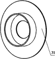
Fig. 5 is the structural representation of centrifugal force smooth rate apparatus 3, flying disc 33 and a frictional disk 31 as shown in Figure 7 of comprising three class 1/3rd annulars as shown in Figure 6, described frictional disk 31 is a disc flywheel spare, side at frictional disk 31 is provided with annular dead turn concentric with it and cylindrical connecting shaft cover 32 as shown in Figure 8, described connecting shaft cover 32 is in the annular dead turn, connecting shaft cover 32 and annular dead turn internal diameter have the interval of certain distance, and the radially first-class distance of described connecting shaft cover 32 is provided with three chutes in array; Described flying disc 33 comprises counterweight 331, friction member 332 and slide bar 333, described counterweight 331 and friction member 332 are welded on the slide bar 333, one end of described slide bar 333 is placed in the corresponding chute, slide bar 333 can be free to slide in chute, described counterweight 331 places the outside of annular dead turn external diameter, described friction member 332 places in the interval between connecting shaft cover 32 and the annular dead turn internal diameter, centrifugal force smooth rate apparatus 3 in the running, friction member 332 can and the annular friction member between produce friction; Described centrifugal force smooth rate apparatus 3 is fixed on the countershaft 4 by connecting shaft cover 32.
Figure 9 shows that the structural representation of terminal deceleration device 2, comprise take-up block, unwrapping wire reel 21 and the retarding rope 27 of being with strigil, the take-up block of described band strigil comprises take-up block 22 and strigil, described strigil comprises the device 25 that declutches, braking tile fragment 24 and braked wheel 23, the thrust of the described device 25 that declutches can preestablish, and remain unchanged, the function class of strigil is similar to the brake gear of bicycle, and the take-up block of band strigil is fixed on the main shaft 5 by key; Unwrapping wire reel 21 is installed on the countershaft 4 by bearing 26, and the inner ring of bearing 26 is fixed on the countershaft 4, and the outer ring is fixed on the unwrapping wire reel 21, and unwrapping wire reel 21 can freely rotate on countershaft 4.
The length of described escaping rope is grown 2~3 meters than the length of retarding rope 27.
Described speed-controlling device can also comprise a housing, and in described main shaft 5 and countershaft 4 housing by the bearing installation, described frictional disk 31 is fixed on the housing.
Described personnel's supporting mechanism is forms mechanism in the present embodiment, described forms mechanism is connected with building by syndeton, as being connected with pin by the both sides of pin with forms mechanism, can realize the disengaging of forms mechanism and building when extracting pin, this pin only just need be extracted when escape.
Described forms mechanism is a rectangular window body mechanism, comprise window frame 7, on fan window 8, upper fold rod 9, lower fan window 10 and following pole 11.Both sides, window frame 7 lower end are fixed with roller 12 respectively, the release of window frame 7 during with convenient escape, and can reduce the friction between the forms mechanism and metope in the decline process, the outside of window frame 7 lower ends is fixed with rubber absorbers, can reduce the impact of forms mechanism when landing.The upper end of last fan window 8 articulates with the upper end of window frame 7, and lower fan window 10 articulates with the lower end of window frame 7, on fan window 8 the left and right sides be connected with window frame 7 left and right sides by upper fold rod 9, pole 11 was connected with window frame 7 left and right sides under the left and right sides of lower fan window 10 was passed through.When forms mechanism is in closed condition, be in the perpendicular, Figure 10 shows that this window structure structural representation in off position.
Figure 11 shows that the structural representation of above-mentioned window structure open mode, when lower fan window 10 was opened fully, lower fan window 10 was vertical with window frame 7, and and ground level, last fan window 8 can be realized self-locking by upper fold rod 9 when open mode, close with the accident that prevents fan window 8.
The housing of described speed-controlling device can be fixed on the external wall of window structure upper end, and the two ends that described escaping rope is fixed on personnel's supporting mechanism are separately fixed on the frame of forms mechanism.
When breaking out of fire or other burst fire-disasters, can be rapidly with on, following sash is opened, by last, following sash and window frame 7 constitute a solid space, enter and be sitting in down on the sash safely for personnel, extract pin, in order to make forms skid off windowsill smoothly, following windowsill face is designed to an outward-dipping inclined-plane, because gravity effect, personnel and the window structure roller 12 by window frame 7 lower ends slowly skids off down windowsill and enters falling state, and personnel and forms mechanism drive life line and fall downwards, and reel begins to put escaping rope and drives main axis rotation, simultaneously, the take-up block in the terminal deceleration device begins to twine retarding rope 27.Gear train will rotatablely move and be delivered to countershaft, trigger the centrifugal force smooth rate apparatus, control quick-acting fruits and obviously strengthen with the increase of rotating speed.When people-window system falls to overhead 2~3 meters, the rope that unwrapping wire reel in the terminal deceleration device will preestablish length has been put, at this moment, terminal deceleration device is triggered, produce the very big moment of resistance, the fast braking main axis rotation makes people-window system stable landing, thereby make personal security flee danger zone, realize escape.
In the present embodiment, the diameter of reel 6 is D
1=70mm; The ring radius is d in the counterweight 331
1=60mm, outer shroud radius are d
2=90mm; The gear wheel number of teeth is Z
1=100, the pinion number of teeth is Z
2=30, large and small module is m
1=m
2=1.5mm; The thrust of setting terminal deceleration device 2 is 51.45N, and the actual peak acceleration that records terminal moderating process is 3m/s
2, the maximal rate when personnel and forms mechanism descend is 0.87m/s.
The above only is a preferred implementation of the present utility model; be noted that for those skilled in the art; under the prerequisite that does not break away from the utility model principle; can also make some improvements and modifications, these improvements and modifications also should be considered as protection domain of the present utility model.
Claims (10)
1. high-rise life saving self-help apparatus, it is characterized in that: described escape self-help apparatus comprises personnel's supporting mechanism and speed-controlling device; Described speed-controlling device comprises main shaft (5), countershaft (4), two reels (6), gear train (1), centrifugal force smooth rate apparatus (3) and terminal deceleration device (2);
Described two reels (6) are wound with the identical escaping rope of length respectively, and described escaping rope one end is fixed on the reel (6), and the other end is fixed on described personnel's supporting mechanism, and reel (6) is fixed on main shaft (5) two ends;
A gear of described gear train (1) is fixed on the main shaft (5), and another gear is fixed on the countershaft (4);
Described centrifugal force smooth rate apparatus (3) comprises frictional disk (31) and flying disc (33), described frictional disk (31) is a disc flywheel spare, side at frictional disk (31) is provided with cylindrical connecting shaft cover (32) and the annular dead turn concentric with it, and the footpath of described connecting shaft cover (32) upwards is provided with chute; Described flying disc (33) comprises counterweight (331), friction member (332) and slide bar (333), and described counterweight (331) and friction member (332) are fixed on the slide bar (333), and an end of described slide bar is placed in the described chute; Described centrifugal force smooth rate apparatus (3) is fixed on main shaft (5) or the countershaft (4) by connecting shaft cover (32);
Described terminal deceleration device (2) comprises take-up block, unwrapping wire reel (21) and the retarding rope (27) of being with strigil, one of them is installed in the take-up block of described band strigil and unwrapping wire reel (21) on the main shaft (5), another is installed on the countershaft (4), and the take-up block of described band strigil and unwrapping wire reel (21) are connected the two ends of retarding rope (27) respectively.
2. high-rise life saving self-help apparatus according to claim 1 is characterized in that: the number of described flying disc (33) is more than two.
3. high-rise life saving self-help apparatus according to claim 1 is characterized in that: the length of described retarding rope (27) is less than the length of described escaping rope.
4. high-rise life saving self-help apparatus according to claim 1, it is characterized in that: described centrifugal force smooth rate apparatus (3) is fixed on the countershaft (4) by connecting shaft cover (32), the take-up block of described band strigil is fixed on the main shaft (4), and described unwrapping wire reel (21) is installed on the countershaft (5).
5. high-rise life saving self-help apparatus according to claim 4 is characterized in that: described unwrapping wire reel (21) is installed on the countershaft (4) by bearing (26).
6. high-rise life saving self-help apparatus according to claim 1 is characterized in that: described speed-controlling device also comprises housing, and described main shaft (5) and countershaft (4) are installed in the housing, and described frictional disk (31) is fixed on the housing.
7. high-rise life saving self-help apparatus according to claim 1 is characterized in that: described personnel's supporting mechanism is a forms mechanism, and described forms mechanism flexibly connects by jockey and building.
8. high-rise life saving self-help apparatus according to claim 7, it is characterized in that: described forms mechanism is a rectangular window body structure, comprise window frame (7) and sash, window frame (7) flexibly connects by described jockey and building, during described forms mechanism opening, have at least a sash to take for personnel.
9. high-rise life saving self-help apparatus according to claim 8, it is characterized in that: described sash comprises fan window (8) and lower fan window (10), the upper end of last fan window (8) and the upper end of window frame (7) articulate, lower fan window (10) articulates with the lower end of window frame (7), the left and right sides of last fan window (8) is connected with window frame (7) left and right sides by upper fold rod (9), and pole (11) connected with window frame (7) left and right sides under the left and right sides of lower fan window (10) was passed through.
10. high-rise life saving self-help apparatus according to claim 7 is characterized in that: the both sides of described window frame (7) lower end are provided with roller (12).
Priority Applications (1)
| Application Number | Priority Date | Filing Date | Title |
|---|---|---|---|
| CN2010202025176U CN201701658U (en) | 2010-05-25 | 2010-05-25 | Tall building escape self rescue device |
Applications Claiming Priority (1)
| Application Number | Priority Date | Filing Date | Title |
|---|---|---|---|
| CN2010202025176U CN201701658U (en) | 2010-05-25 | 2010-05-25 | Tall building escape self rescue device |
Publications (1)
| Publication Number | Publication Date |
|---|---|
| CN201701658U true CN201701658U (en) | 2011-01-12 |
Family
ID=43438802
Family Applications (1)
| Application Number | Title | Priority Date | Filing Date |
|---|---|---|---|
| CN2010202025176U Expired - Fee Related CN201701658U (en) | 2010-05-25 | 2010-05-25 | Tall building escape self rescue device |
Country Status (1)
| Country | Link |
|---|---|
| CN (1) | CN201701658U (en) |
Cited By (12)
| Publication number | Priority date | Publication date | Assignee | Title |
|---|---|---|---|---|
| CN105083310A (en) * | 2015-08-25 | 2015-11-25 | 中铁二院工程集团有限责任公司 | Passenger emergency evacuation system of suspension-type monorail transit train |
| WO2015180629A1 (en) * | 2014-05-26 | 2015-12-03 | 旭榕吴 | Rope releasing device with fire-fighting and rescuing functions |
| CN105451822A (en) * | 2013-08-05 | 2016-03-30 | 依瓦库特国际物业有限公司 | Device for evacuating individuals |
| CN105664386A (en) * | 2016-04-14 | 2016-06-15 | 贵州大学 | High-rise cyclic escape device |
| CN105688342A (en) * | 2016-04-14 | 2016-06-22 | 贵州大学 | Rope decelerating and recycling structure for high-rise circulation escaping devices |
| CN107281662A (en) * | 2017-08-17 | 2017-10-24 | 张宪友 | Emergency escape self-rescuer |
| CN109045498A (en) * | 2017-12-26 | 2018-12-21 | 珠海索奇电子科技有限公司 | A kind of driving control system of life-saving device for high-rise fire hazard |
| CN109663230A (en) * | 2019-02-27 | 2019-04-23 | 徐良 | From deceleration mechanism and escaping mechanism |
| CN110585613A (en) * | 2019-08-06 | 2019-12-20 | 厦门信智创联科技有限公司 | High-rise escape device |
| CN110902500A (en) * | 2019-12-03 | 2020-03-24 | 湖南力诚新能源科技有限公司 | Cable reel with 360° swivel outlet |
| CN113148886A (en) * | 2021-04-21 | 2021-07-23 | 湖北恒子工程技术有限公司 | Winch device for engineering machinery |
| CN119951056A (en) * | 2025-01-20 | 2025-05-09 | 广东宏邦金属制造有限公司 | An escape device that can be hidden under a window |
-
2010
- 2010-05-25 CN CN2010202025176U patent/CN201701658U/en not_active Expired - Fee Related
Cited By (19)
| Publication number | Priority date | Publication date | Assignee | Title |
|---|---|---|---|---|
| CN105451822A (en) * | 2013-08-05 | 2016-03-30 | 依瓦库特国际物业有限公司 | Device for evacuating individuals |
| CN105451822B (en) * | 2013-08-05 | 2019-05-03 | 依瓦库特国际物业有限公司 | Equipment used to evacuate individuals |
| WO2015180629A1 (en) * | 2014-05-26 | 2015-12-03 | 旭榕吴 | Rope releasing device with fire-fighting and rescuing functions |
| CN105083310B (en) * | 2015-08-25 | 2018-04-27 | 中铁二院工程集团有限责任公司 | Passenger's abort escape system of suspension type monorail traffic train |
| CN105083310A (en) * | 2015-08-25 | 2015-11-25 | 中铁二院工程集团有限责任公司 | Passenger emergency evacuation system of suspension-type monorail transit train |
| CN105688342B (en) * | 2016-04-14 | 2020-12-11 | 贵州大学 | A rope deceleration and recovery structure for a high-rise circular escape device |
| CN105664386A (en) * | 2016-04-14 | 2016-06-15 | 贵州大学 | High-rise cyclic escape device |
| CN105688342A (en) * | 2016-04-14 | 2016-06-22 | 贵州大学 | Rope decelerating and recycling structure for high-rise circulation escaping devices |
| CN107281662A (en) * | 2017-08-17 | 2017-10-24 | 张宪友 | Emergency escape self-rescuer |
| CN109045498A (en) * | 2017-12-26 | 2018-12-21 | 珠海索奇电子科技有限公司 | A kind of driving control system of life-saving device for high-rise fire hazard |
| CN109663230A (en) * | 2019-02-27 | 2019-04-23 | 徐良 | From deceleration mechanism and escaping mechanism |
| CN109663230B (en) * | 2019-02-27 | 2023-11-28 | 徐良 | Self-deceleration mechanism and escape mechanism |
| CN110585613A (en) * | 2019-08-06 | 2019-12-20 | 厦门信智创联科技有限公司 | High-rise escape device |
| CN110585613B (en) * | 2019-08-06 | 2024-01-09 | 厦门信智创联科技有限公司 | High-rise escape device |
| CN110902500A (en) * | 2019-12-03 | 2020-03-24 | 湖南力诚新能源科技有限公司 | Cable reel with 360° swivel outlet |
| CN113148886A (en) * | 2021-04-21 | 2021-07-23 | 湖北恒子工程技术有限公司 | Winch device for engineering machinery |
| CN113148886B (en) * | 2021-04-21 | 2023-01-24 | 湖北恒子工程技术有限公司 | Winch device for engineering machinery |
| CN119951056A (en) * | 2025-01-20 | 2025-05-09 | 广东宏邦金属制造有限公司 | An escape device that can be hidden under a window |
| CN119951056B (en) * | 2025-01-20 | 2025-10-31 | 晓轩科技(广东)有限公司 | Escape device capable of being hidden under window |
Similar Documents
| Publication | Publication Date | Title |
|---|---|---|
| CN101920074B (en) | High-rise escape machine and automatic escape control method | |
| CN209137797U (en) | A kind of driving control system of life-saving device for high-rise fire hazard | |
| CN101884826B (en) | Outdoor hanging type emergency fireproof escape capsule for high-rise building | |
| CN207356383U (en) | A kind of fall-slowing device for rescuing from high building | |
| CN209848166U (en) | Dual-damping high-altitude descent control device | |
| CN201840794U (en) | Speed-self-adjustable high-rise escaping device | |
| CN201807097U (en) | Emergency fire escape trunk hung outside room on high level | |
| CN206896614U (en) | A kind of two-way speed reduction in landing device | |
| CN201840798U (en) | Quick escaping device for tall building | |
| CN106552337A (en) | One kind is multi-functional to put rope equipment | |
| CN106552365A (en) | One kind is multi-functional to put rope equipment | |
| CN106552332A (en) | It is a kind of with the multi-functional building for putting rope equipment | |
| CN106552363A (en) | One kind is multi-functional to put rope equipment | |
| CN106552335A (en) | One kind is multi-functional to put rope equipment | |
| CN106552345A (en) | It is a kind of with the multi-functional building for putting rope equipment | |
| CN103239809B (en) | High-rise escape device | |
| CN106552343A (en) | It is a kind of with the multi-functional building for putting rope equipment | |
| CN106552364A (en) | It is a kind of with the multi-functional building for putting rope equipment | |
| CN107982765A (en) | One kind is multi-functional to put rope equipment | |
| CN107982680A (en) | One kind is multi-functional to put rope equipment | |
| CN109847207A (en) | A kind of multi-functional with rescue function puts rope equipment | |
| CN110478774A (en) | A kind of multi-functional with rescue function puts rope equipment | |
| CN110478787A (en) | A kind of multi-functional with rescue function puts rope equipment | |
| CN106552344A (en) | One kind is multi-functional to put rope equipment | |
| CN106552360A (en) | One kind is multi-functional to put rope equipment |
Legal Events
| Date | Code | Title | Description |
|---|---|---|---|
| C14 | Grant of patent or utility model | ||
| GR01 | Patent grant | ||
| C17 | Cessation of patent right | ||
| CF01 | Termination of patent right due to non-payment of annual fee |
Granted publication date: 20110112 Termination date: 20110525 |