CN201699094U - Automatic adhesive tape winding machine for battery - Google Patents
Automatic adhesive tape winding machine for battery Download PDFInfo
- Publication number
- CN201699094U CN201699094U CN2010202321466U CN201020232146U CN201699094U CN 201699094 U CN201699094 U CN 201699094U CN 2010202321466 U CN2010202321466 U CN 2010202321466U CN 201020232146 U CN201020232146 U CN 201020232146U CN 201699094 U CN201699094 U CN 201699094U
- Authority
- CN
- China
- Prior art keywords
- plate
- adhesive tape
- fixed
- location
- base plate
- Prior art date
- Legal status (The legal status is an assumption and is not a legal conclusion. Google has not performed a legal analysis and makes no representation as to the accuracy of the status listed.)
- Expired - Lifetime
Links
- 239000002390 adhesive tape Substances 0.000 title claims abstract description 38
- 238000004804 winding Methods 0.000 title abstract description 11
- 238000006073 displacement reaction Methods 0.000 claims abstract description 4
- NJPPVKZQTLUDBO-UHFFFAOYSA-N novaluron Chemical compound C1=C(Cl)C(OC(F)(F)C(OC(F)(F)F)F)=CC=C1NC(=O)NC(=O)C1=C(F)C=CC=C1F NJPPVKZQTLUDBO-UHFFFAOYSA-N 0.000 claims description 7
- 230000008878 coupling Effects 0.000 claims description 6
- 238000010168 coupling process Methods 0.000 claims description 6
- 238000005859 coupling reaction Methods 0.000 claims description 6
- 238000005452 bending Methods 0.000 claims description 2
- 238000003032 molecular docking Methods 0.000 claims description 2
- 229910001416 lithium ion Inorganic materials 0.000 abstract description 25
- QSNQXZYQEIKDPU-UHFFFAOYSA-N [Li].[Fe] Chemical compound [Li].[Fe] QSNQXZYQEIKDPU-UHFFFAOYSA-N 0.000 abstract description 9
- 238000004519 manufacturing process Methods 0.000 abstract description 9
- 230000000903 blocking effect Effects 0.000 abstract 2
- 230000000149 penetrating effect Effects 0.000 abstract 1
- XEEYBQQBJWHFJM-UHFFFAOYSA-N Iron Chemical compound [Fe] XEEYBQQBJWHFJM-UHFFFAOYSA-N 0.000 description 32
- HBBGRARXTFLTSG-UHFFFAOYSA-N Lithium ion Chemical compound [Li+] HBBGRARXTFLTSG-UHFFFAOYSA-N 0.000 description 16
- 229910052742 iron Inorganic materials 0.000 description 16
- 230000005611 electricity Effects 0.000 description 4
- 230000009286 beneficial effect Effects 0.000 description 1
- 238000005265 energy consumption Methods 0.000 description 1
- 238000005516 engineering process Methods 0.000 description 1
- 230000007613 environmental effect Effects 0.000 description 1
- 238000010295 mobile communication Methods 0.000 description 1
- 230000001105 regulatory effect Effects 0.000 description 1
Images


Classifications
-
- Y—GENERAL TAGGING OF NEW TECHNOLOGICAL DEVELOPMENTS; GENERAL TAGGING OF CROSS-SECTIONAL TECHNOLOGIES SPANNING OVER SEVERAL SECTIONS OF THE IPC; TECHNICAL SUBJECTS COVERED BY FORMER USPC CROSS-REFERENCE ART COLLECTIONS [XRACs] AND DIGESTS
- Y02—TECHNOLOGIES OR APPLICATIONS FOR MITIGATION OR ADAPTATION AGAINST CLIMATE CHANGE
- Y02E—REDUCTION OF GREENHOUSE GAS [GHG] EMISSIONS, RELATED TO ENERGY GENERATION, TRANSMISSION OR DISTRIBUTION
- Y02E60/00—Enabling technologies; Technologies with a potential or indirect contribution to GHG emissions mitigation
- Y02E60/10—Energy storage using batteries
-
- Y—GENERAL TAGGING OF NEW TECHNOLOGICAL DEVELOPMENTS; GENERAL TAGGING OF CROSS-SECTIONAL TECHNOLOGIES SPANNING OVER SEVERAL SECTIONS OF THE IPC; TECHNICAL SUBJECTS COVERED BY FORMER USPC CROSS-REFERENCE ART COLLECTIONS [XRACs] AND DIGESTS
- Y02—TECHNOLOGIES OR APPLICATIONS FOR MITIGATION OR ADAPTATION AGAINST CLIMATE CHANGE
- Y02P—CLIMATE CHANGE MITIGATION TECHNOLOGIES IN THE PRODUCTION OR PROCESSING OF GOODS
- Y02P70/00—Climate change mitigation technologies in the production process for final industrial or consumer products
- Y02P70/50—Manufacturing or production processes characterised by the final manufactured product
Landscapes
- Battery Electrode And Active Subsutance (AREA)
Abstract
The utility model provides an automatic adhesive tape winding machine for a battery, which relates to winding equipment for an iron lithium ion battery in an electric bicycle. The automatic adhesive tape winding machine used for winding the battery solves the problems that electric cores are not flushed with one another up and down, back and forth and left and right, an adhesive tape is uneven and not flat, and the production efficiency is low when manual winding is carried out on the electric cores. A cylinder is fixed on the upper surface of a top plate, the lower end part of a piston rod is fixed with the upper surface of a pressing plate, vertically-upward long grooves are respectively arranged on the upper end faces of a left supporting plate and a right supporting plate so as to form two parallel sliding ways, the pressing plate can generate certain displacements along the sliding ways, the upper end of a short shaft is connected at the middle position of the lower surface of the pressing plate by a bearing, the lower end part of the short shaft is fixed at the middle position of the upper surface of an upper positioning plate, the upper end part of a long shaft is fixed at the middle position of the plate surface of a lower positioning plate, and the lower end of the long shaft is connected with a bottom plate by the bearing after penetrating through the bottom plate. Positioning blocking edges which present the shapes of turning rulers are respectively arranged at the rims of the lower surface of the upper positioning plate and the upper surface of the lower positioning plate, and quick clamp forceps are arranged oppositely to the short edges of the positioning blocking edges.
Description
Technical field
The utility model relates to the Wiring apparatus of iron lithium ion battery in a kind of electric bicycle.
Background technology
In recent years, fast development along with China's mobile communication industry and portable type electronic product and electric motor car, the iron lithium ion battery is as the rechargeable battery of a kind of novel, high power capacity, safety, in equipment such as mobile phone, digital product, electric bicycle, be widely adopted, the iron lithium ion battery has become the indispensable accessory of these equipment as power supply.Electric bicycle is the vehicles that are applicable to that individual short distance is used, the advantage of have zero discharge, low noise, low energy consumption, hang down usage charges, safety being ridden easily, the trend that meets energy-saving and environmental protection, therefore popularized rapidly, this has also brought a large amount of uses of the electronic bicycle battery of iron lithium ion.
The electronic bicycle battery of iron lithium ion generally is divided into two kinds of 36V and 48V, the electronic bicycle battery of 36V iron lithium ion is composed in series by 11 iron lithium-ion electric cores, the electronic bicycle battery of 48V iron lithium ion is composed in series by 15 iron lithium-ion electric cores, when the electronic bicycle battery of assembling iron lithium ion, at first well-graded iron lithium-ion electric core to be wound in 36V or the required battery pack of 48V with adhesive tape, about the battery pack quality requirement that is twined, front and back with about want all that concordant and adhesive tape twines also evenly straight.The battery pack that only meets above-mentioned requirements just can change next station over to.Owing to generally all adopt manual mode to twine battery pack at present, therefore twine the bottleneck that station becomes whole production line.Having following reason to cause to twine station becomes bottleneck: 1. manual be difficult to accomplish between electricity core and the electric core when twining electric core about, front and back with about all concordant; 2. manual when twining electric core adhesive tape also be difficult to twine evenly straight; 3. need the actuator; 4. production efficiency is low; 5. winding mass can not guarantee.
Summary of the invention
The purpose of this utility model provides a kind of battery adhesive tape automatic wrapping machine, with solve manual when twining electric core between electricity core and the electric core about, front and back with about not concordant problem and adhesive tape is inhomogeneous, not straight and production efficiency is low when twining electric core problem.It comprises Adhesive tape reel holder 2, Adhesive tape reel 3, rectangular frame, pressing plate 5, cylinder 8, last location-plate 13, an active grab 14-1, No. two active grab 14-2, following location-plate 16, major axis 17 and minor axis 11, rectangular frame is by left supported plate 4, top board 6, right supported plate 15 and base plate 18 surround, Adhesive tape reel holder 2 is fixed on the frame outside of rectangular frame, Adhesive tape reel 3 be fixed in the Adhesive tape reel holder 2 and axial line vertically upward, cylinder 8 is fixed on the upper surface of top board 6 and the piston rod of cylinder 8 penetrates in top board 6, the upper surface of the bottom of piston rod and pressing plate 5 fixes, all have vertically upward elongated slot H on the upper head plate face of left supported plate 4 and right supported plate 15 to form two parallel slideways, can be in the elongated slot H thereby the end, two ends, the left and right sides of pressing plate 5 is inserted in respectively along the slideway displacement, the end, upper end of minor axis 11 is connected the lower surface centre position of pressing plate 5 by bearing, the end, lower end of minor axis 11 is fixed on the centre position of location-plate 13 upper surfaces, the end, upper end of major axis 17 is fixed on down the plate face centre position of location-plate 16, the lower end of major axis 17 passes base plate 18 and is connected by bearing with 18 of base plates, be formed with location rib 13-1 on " turning chi " shape on the lower surface of last location-plate 13 along the edge, the minor face opposite of last location rib 13-1 is provided with active grab 14-1 No. one, No. one active grab 14-1 is fixed on the lower surface of location-plate 13, be formed with location rib 16-1 under " turning chi " shape on following location-plate 16 upper surfaces along the edge, the minor face opposite of locating rib 16-1 down is provided with active grab 14-2 No. two, No. two active grab 14-2 is fixed on down on the upper surface of location-plate 16, minor axis 11 and major axis 17 concentrics, the upper surface of base plate 18 is identical with the level height of Adhesive tape reel 3 lower ends, on locate rib 13-1 and down location rib 16-1 is corresponding up and down.
During work, the adhesive tape dish that is used to twine the iron lithium-ion electric core is inserted in Adhesive tape reel 3, the iron lithium-ion electric core group that meets quantitative requirement along the length direction of location-plate 16 down be arranged in down on the location-plate 16 and snap under locate on the rib 16-1, thereby finish the location of iron lithium-ion electric core, allow the piston rod in the cylinder 8 stretch out then downwards, thereby make pressing plate 5 be fastened on iron lithium-ion electric core group upper end, clamp battery pack along the elongated slot H supreme location-plate 13 that glides.The location rib 13-1 that goes up on last location-plate 13 lower surfaces has realized the location on the iron lithium-ion electric core group.With active grab 14-1 and No. two active grab 14-2 iron lithium-ion electric core group is clamped between upper and lower location rib and two active grabs respectively.The end of adhesive tape is sticked on the electric core side of iron lithium-ion electric core group, in horizontal plane, rotate iron lithium-ion electric core group then, because the major axis 17 that is connected with following location-plate 16 is supporting with the minor axis 11 that is connected with last location-plate 13, following location-plate, make the steadily rotation in horizontal plane of iron lithium-ion electric core group, adhesive tape can be even, be wrapped in the surface of iron lithium-ion electric core group straightly, since iron lithium-ion electric core group obtained time location-plate 16 and down location rib 16-1 about, about and the location of front and back all directions, fixed by active grab again, therefore when having solved the electric core of manual winding between electricity core and the electric core about, before and after with about not concordant problem.Because mechanical device has replaced manual winding adhesive tape, has improved production efficiency.
The utility model compared with prior art has following beneficial effect: when one, twining electric core between electricity core and the electric core about, front and back, the left and right sides is concordant, when twining electric core adhesive tape twine evenly straight, thereby guaranteed the winding mass of winding station; Two, reduce the operator training time of twining station, alleviated working strength of workers simultaneously; Three, improve production efficiency, and reduced production cost.The utility model also has to be installed and easy to use, structure and manufacture craft are simple, be fit to produce in enormous quantities and reduced advantage such as production cost.
Description of drawings
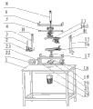
Fig. 1 is a perspective view of the present utility model; Fig. 2 is a stereochemical structure decomposing schematic representation of the present utility model; Fig. 3 is the perspective view of the utility model pressing plate 5; Fig. 4 is the perspective view of the utility model active grab.
Embodiment
Embodiment one: specify present embodiment below in conjunction with Fig. 1 to Fig. 3.Present embodiment comprises Adhesive tape reel holder 2, Adhesive tape reel 3, rectangular frame, pressing plate 5, cylinder 8, last location-plate 13, an active grab 14-1, No. two active grab 14-2, following location-plate 16, major axis 17 and minor axis 11, rectangular frame is by left supported plate 4, top board 6, right supported plate 15 and base plate 18 surround, Adhesive tape reel holder 2 is fixed on the frame outside of rectangular frame, Adhesive tape reel 3 be fixed in the Adhesive tape reel holder 2 and axial line vertically upward, cylinder 8 is fixed on the upper surface of top board 6 and the piston rod of cylinder 8 penetrates in top board 6, the upper surface of the bottom of piston rod and pressing plate 5 fixes, all have vertically upward elongated slot H on the upper head plate face of left supported plate 4 and right supported plate 15 to form two parallel slideways, can be in the elongated slot H thereby the end, two ends, the left and right sides of pressing plate 5 is inserted in respectively along the slideway displacement, the end, upper end of minor axis 11 is connected the lower surface centre position of pressing plate 5 by bearing, the end, lower end of minor axis 11 is fixed on the centre position of location-plate 13 upper surfaces, the end, upper end of major axis 17 is fixed on down the plate face centre position of location-plate 16, the lower end of major axis 17 passes base plate 18 and is connected by bearing with 18 of base plates, be formed with location rib 13-1 on " turning chi " shape on the lower surface of last location-plate 13 along the edge, the minor face opposite of last location rib 13-1 is provided with active grab 14-1 No. one, No. one active grab 14-1 is fixed on the lower surface of location-plate 13, be formed with location rib 16-1 under " turning chi " shape on following location-plate 16 upper surfaces along the edge, the minor face opposite of locating rib 16-1 down is provided with active grab 14-2 No. two, No. two active grab 14-2 is fixed on down on the upper surface of location-plate 16, minor axis 11 and major axis 17 concentrics, the upper surface of base plate 18 is identical with the level height of Adhesive tape reel 3 lower ends, on locate rib 13-1 and down location rib 16-1 is corresponding up and down.
Embodiment two: specify present embodiment below in conjunction with Fig. 1 and Fig. 2.The difference of present embodiment and execution mode one is: it also comprises workbench 1, right base plate support plate 19, shaft coupling 20, motor yoke plate 21, machine governor 22, left bottom plate support plate 23, adjustable speed motor 24, the upper end of right base plate support plate 19 and left bottom plate support plate 23 is separately fixed at the two ends, the left and right sides of base plate 18 lower surfaces, the lower end of right base plate support plate 19 and left bottom plate support plate 23 is separately fixed at the two ends, the left and right sides of motor yoke plate 21, motor yoke plate 21 is laid and is fixed on the upper surface of workbench 1, adjustable speed motor 24 is fixed on the platen lower surface of workbench 1, shaft coupling 20 is arranged between motor yoke plate 21 and the base plate 18, shaft coupling 20 is docking together the motor shaft of adjustable speed motor 24 and major axis 17, and machine governor 22 is arranged on the supply terminals of adjustable speed motor 24 to regulate and control its rotating speed.So be provided with, location-plate 16 and iron lithium-ion electric core group are rotated and are twined adhesive tape under can driving by adjustable speed motor 24, have improved mechanization degree more, and adjustable speed motor 24 can be regulated and control the rotating speed of adjustable speed motor 24.
Embodiment three: specify present embodiment below in conjunction with Fig. 4.The difference of present embodiment and execution mode one is: a described active grab 14-1 is made up of pedestal I, sliding sleeve II, push rod III, pull bar IV and connecting rod V, the sliding sleeve II is fixed on the front end of pedestal I, the push rod III is inserted in the sliding sleeve II, one end of pull bar IV is hinged on the rear end of pedestal I, one end of connecting rod V is hinged on the middle part of pull bar IV, the other end of connecting rod V is hinged on the rear end of push rod III, and the first half of pull bar IV forms bending backward at the hinge hole place.During use, the pedestal I is fixed on the lower surface of location-plate 13, if push away the free end of pull bar IV forward, the connecting rod V is penetrator ram III and form self-locking forward, and pulling back the pull bar IV could recall the push rod III come.So be provided with, can realize the fixing and disengagement of iron lithium-ion electric core group fast, No. two active grab 14-2 is identical with the structure of an active grab 14-1.
Claims (3)
1. battery adhesive tape automatic wrapping machine, it is characterized in that it comprises Adhesive tape reel holder (2), Adhesive tape reel (3), rectangular frame, pressing plate (5), cylinder (8), last location-plate (13), an active grab (14-1), No. two active grabs (14-2), following location-plate (16), major axis (17) and minor axis (11), rectangular frame is by left supported plate (4), top board (6), right supported plate (15) and base plate (18) surround, Adhesive tape reel holder (2) is fixed on the frame outside of rectangular frame, Adhesive tape reel (3) be fixed on that Adhesive tape reel holder (2) is gone up and axial line vertically upward, cylinder (8) is fixed on the upper surface of top board (6) and the piston rod of cylinder (8) penetrates in top board (6), the upper surface of the bottom of piston rod and pressing plate (5) fixes, all have vertically upward elongated slot (H) on the upper head plate face of left supported plate (4) and right supported plate (15) to form two parallel slideways, thereby the end, two ends, the left and right sides of pressing plate (5) is inserted in an elongated slot (H) respectively can be along the slideway displacement interior, the end, upper end of minor axis (11) is connected the lower surface centre position of pressing plate (5) by bearing, the end, lower end of minor axis (11) is fixed on the centre position of location-plate (13) upper surface, the end, upper end of major axis (17) is fixed on down the plate face centre position of location-plate (16), the lower end of major axis (17) pass base plate (18) and with base plate (18) between be connected by bearing, be formed with location rib (13-1) on " turning chi " shape on the lower surface of last location-plate (13) along the edge, the minor face opposite of last location rib (13-1) is provided with an active grab (14-1), an active grab (14-1) is fixed on the lower surface of location-plate (13), be formed with location rib (16-1) under " turning chi " shape on following location-plate (16) upper surface along the edge, the minor face opposite of locating rib (16-1) down is provided with No. two active grabs (14-2), No. two active grabs (14-2) are fixed on down on the upper surface of location-plate (16), minor axis (11) and major axis (17) concentric, the upper surface of base plate (18) is identical with the level height of Adhesive tape reel (3) lower end, on locate rib (13-1) and down location rib (16-1) is corresponding up and down.
2. battery adhesive tape automatic wrapping machine according to claim 1, it is characterized in that it also comprises workbench (1), right base plate support plate (19), shaft coupling (20), motor yoke plate (21), machine governor (22), left bottom plate support plate (23), adjustable speed motor (24), the upper end of right base plate support plate (19) and left bottom plate support plate (23) is separately fixed at the two ends, the left and right sides of base plate (18) lower surface, the lower end of right base plate support plate (19) and left bottom plate support plate (23) is separately fixed at the two ends, the left and right sides of motor yoke plate (21), motor yoke plate (21) is laid and is fixed on the upper surface of workbench (1), adjustable speed motor (24) is fixed on the platen lower surface of workbench (1), shaft coupling (20) is arranged between motor yoke plate (21) and the base plate (18), shaft coupling (20) is docking together the motor shaft of adjustable speed motor (24) and major axis (17), and machine governor (22) is arranged on the supply terminals of adjustable speed motor (24) to regulate and control its rotating speed.
3. battery adhesive tape automatic wrapping machine according to claim 1, it is characterized in that a described active grab (14-1) is by pedestal (I), sliding sleeve (II), push rod (III), pull bar (IV) and connecting rod (V) are formed, sliding sleeve (II) is fixed on the front end of pedestal (I), push rod (III) is inserted in the sliding sleeve (II), one end of pull bar (IV) is hinged on the rear end of pedestal (I), one end of connecting rod (V) is hinged on the middle part of pull bar (IV), the other end of connecting rod (V) is hinged on the rear end of push rod (III), and the first half of pull bar (IV) forms bending backward at the hinge hole place.
Priority Applications (1)
| Application Number | Priority Date | Filing Date | Title |
|---|---|---|---|
| CN2010202321466U CN201699094U (en) | 2010-06-22 | 2010-06-22 | Automatic adhesive tape winding machine for battery |
Applications Claiming Priority (1)
| Application Number | Priority Date | Filing Date | Title |
|---|---|---|---|
| CN2010202321466U CN201699094U (en) | 2010-06-22 | 2010-06-22 | Automatic adhesive tape winding machine for battery |
Publications (1)
| Publication Number | Publication Date |
|---|---|
| CN201699094U true CN201699094U (en) | 2011-01-05 |
Family
ID=43400340
Family Applications (1)
| Application Number | Title | Priority Date | Filing Date |
|---|---|---|---|
| CN2010202321466U Expired - Lifetime CN201699094U (en) | 2010-06-22 | 2010-06-22 | Automatic adhesive tape winding machine for battery |
Country Status (1)
| Country | Link |
|---|---|
| CN (1) | CN201699094U (en) |
Cited By (2)
| Publication number | Priority date | Publication date | Assignee | Title |
|---|---|---|---|---|
| CN109755627A (en) * | 2019-01-28 | 2019-05-14 | 深圳市易为派科技有限公司 | The knot installation and its binding method of battery modules |
| CN117374409A (en) * | 2023-10-08 | 2024-01-09 | 白景礼 | A lithium battery processing system and processing method |
-
2010
- 2010-06-22 CN CN2010202321466U patent/CN201699094U/en not_active Expired - Lifetime
Cited By (2)
| Publication number | Priority date | Publication date | Assignee | Title |
|---|---|---|---|---|
| CN109755627A (en) * | 2019-01-28 | 2019-05-14 | 深圳市易为派科技有限公司 | The knot installation and its binding method of battery modules |
| CN117374409A (en) * | 2023-10-08 | 2024-01-09 | 白景礼 | A lithium battery processing system and processing method |
Similar Documents
| Publication | Publication Date | Title |
|---|---|---|
| CN203150668U (en) | Coiling device | |
| CN201638908U (en) | Full-automatic battery core winding device | |
| CN201862534U (en) | Automatic glue dispenser of square lithium ion battery | |
| CN201783697U (en) | Cutting device | |
| CN203474041U (en) | Rolling feed mechanism of battery winding machine | |
| CN216913858U (en) | Taking device of battery cell | |
| CN209150240U (en) | A cell mylar tape folding device | |
| CN201741766U (en) | Roll needle mechanism | |
| CN214683684U (en) | Utmost point ear device is rolled over to electricity core | |
| CN221026852U (en) | Precise wire arrangement device for enameled wires | |
| CN202127056U (en) | Fixture locating mechanism for laser welding of lug leading sheets and pole | |
| CN203026607U (en) | Cell packing device | |
| CN213905538U (en) | Modular strapping device compatible with pouch and cube batteries | |
| CN218744723U (en) | Positioning mechanism for metal plate thermal forming die | |
| CN207684635U (en) | A kind of double-station automatic coil winding machine | |
| CN202930500U (en) | Winding mechanism of nickel-metal hydride cylindrical battery full-automatic winding all-in-one machine | |
| CN202817110U (en) | Battery overturning and deslagging mechanism | |
| CN206057085U (en) | A tensile testing machine | |
| CN203474033U (en) | Film pulling and clamping device for storage battery pole group enveloping machine | |
| CN202864523U (en) | Guiding device for outputting and clamping conveying of septum of battery electrode plate | |
| CN208862106U (en) | A kind of horizontal servo battery hot pressing chemical conversion machine | |
| CN103022568A (en) | Battery cell packaging device | |
| CN211789334U (en) | Positive negative pole winder is used in lithium cell production | |
| CN202523808U (en) | Dual-rod type winding needle for winding polymer square lithium ion battery | |
| CN107958991B (en) | Sheet making machine |
Legal Events
| Date | Code | Title | Description |
|---|---|---|---|
| C14 | Grant of patent or utility model | ||
| GR01 | Patent grant | ||
| CX01 | Expiry of patent term |
Granted publication date: 20110105 |
|
| CX01 | Expiry of patent term |