CN201671469U - a damper - Google Patents
a damper Download PDFInfo
- Publication number
- CN201671469U CN201671469U CN2010201791981U CN201020179198U CN201671469U CN 201671469 U CN201671469 U CN 201671469U CN 2010201791981 U CN2010201791981 U CN 2010201791981U CN 201020179198 U CN201020179198 U CN 201020179198U CN 201671469 U CN201671469 U CN 201671469U
- Authority
- CN
- China
- Prior art keywords
- movable part
- groove
- shell
- lower shell
- housing
- Prior art date
- Legal status (The legal status is an assumption and is not a legal conclusion. Google has not performed a legal analysis and makes no representation as to the accuracy of the status listed.)
- Expired - Lifetime
Links
- 238000013016 damping Methods 0.000 claims abstract description 13
- 230000009286 beneficial effect Effects 0.000 abstract description 3
- 230000002349 favourable effect Effects 0.000 abstract 1
- 230000003139 buffering effect Effects 0.000 description 1
- 230000002860 competitive effect Effects 0.000 description 1
- 238000010586 diagram Methods 0.000 description 1
- 230000000694 effects Effects 0.000 description 1
- 238000004880 explosion Methods 0.000 description 1
- 238000004519 manufacturing process Methods 0.000 description 1
- 238000000034 method Methods 0.000 description 1
- 230000008719 thickening Effects 0.000 description 1
Images


Classifications
-
- E—FIXED CONSTRUCTIONS
- E05—LOCKS; KEYS; WINDOW OR DOOR FITTINGS; SAFES
- E05F—DEVICES FOR MOVING WINGS INTO OPEN OR CLOSED POSITION; CHECKS FOR WINGS; WING FITTINGS NOT OTHERWISE PROVIDED FOR, CONCERNED WITH THE FUNCTIONING OF THE WING
- E05F1/00—Closers or openers for wings, not otherwise provided for in this subclass
- E05F1/08—Closers or openers for wings, not otherwise provided for in this subclass spring-actuated, e.g. for horizontally sliding wings
- E05F1/16—Closers or openers for wings, not otherwise provided for in this subclass spring-actuated, e.g. for horizontally sliding wings for sliding wings
-
- E—FIXED CONSTRUCTIONS
- E05—LOCKS; KEYS; WINDOW OR DOOR FITTINGS; SAFES
- E05D—HINGES OR SUSPENSION DEVICES FOR DOORS, WINDOWS OR WINGS
- E05D15/00—Suspension arrangements for wings
- E05D15/06—Suspension arrangements for wings for wings sliding horizontally more or less in their own plane
- E05D15/0621—Details, e.g. suspension or supporting guides
- E05D15/066—Details, e.g. suspension or supporting guides for wings supported at the bottom
- E05D15/0691—Top guides
-
- E—FIXED CONSTRUCTIONS
- E05—LOCKS; KEYS; WINDOW OR DOOR FITTINGS; SAFES
- E05F—DEVICES FOR MOVING WINGS INTO OPEN OR CLOSED POSITION; CHECKS FOR WINGS; WING FITTINGS NOT OTHERWISE PROVIDED FOR, CONCERNED WITH THE FUNCTIONING OF THE WING
- E05F5/00—Braking devices, e.g. checks; Stops; Buffers
- E05F5/003—Braking devices, e.g. checks; Stops; Buffers for sliding wings
-
- E—FIXED CONSTRUCTIONS
- E05—LOCKS; KEYS; WINDOW OR DOOR FITTINGS; SAFES
- E05F—DEVICES FOR MOVING WINGS INTO OPEN OR CLOSED POSITION; CHECKS FOR WINGS; WING FITTINGS NOT OTHERWISE PROVIDED FOR, CONCERNED WITH THE FUNCTIONING OF THE WING
- E05F5/00—Braking devices, e.g. checks; Stops; Buffers
- E05F5/02—Braking devices, e.g. checks; Stops; Buffers specially for preventing the slamming of swinging wings during final closing movement, e.g. jamb stops
- E05F5/027—Braking devices, e.g. checks; Stops; Buffers specially for preventing the slamming of swinging wings during final closing movement, e.g. jamb stops with closing action
-
- E—FIXED CONSTRUCTIONS
- E05—LOCKS; KEYS; WINDOW OR DOOR FITTINGS; SAFES
- E05Y—INDEXING SCHEME ASSOCIATED WITH SUBCLASSES E05D AND E05F, RELATING TO CONSTRUCTION ELEMENTS, ELECTRIC CONTROL, POWER SUPPLY, POWER SIGNAL OR TRANSMISSION, USER INTERFACES, MOUNTING OR COUPLING, DETAILS, ACCESSORIES, AUXILIARY OPERATIONS NOT OTHERWISE PROVIDED FOR, APPLICATION THEREOF
- E05Y2201/00—Constructional elements; Accessories therefor
- E05Y2201/40—Motors; Magnets; Springs; Weights; Accessories therefor
- E05Y2201/404—Function thereof
- E05Y2201/41—Function thereof for closing
- E05Y2201/412—Function thereof for closing for the final closing movement
-
- E—FIXED CONSTRUCTIONS
- E05—LOCKS; KEYS; WINDOW OR DOOR FITTINGS; SAFES
- E05Y—INDEXING SCHEME ASSOCIATED WITH SUBCLASSES E05D AND E05F, RELATING TO CONSTRUCTION ELEMENTS, ELECTRIC CONTROL, POWER SUPPLY, POWER SIGNAL OR TRANSMISSION, USER INTERFACES, MOUNTING OR COUPLING, DETAILS, ACCESSORIES, AUXILIARY OPERATIONS NOT OTHERWISE PROVIDED FOR, APPLICATION THEREOF
- E05Y2201/00—Constructional elements; Accessories therefor
- E05Y2201/60—Suspension or transmission members; Accessories therefor
- E05Y2201/622—Suspension or transmission members elements
- E05Y2201/688—Rollers
- E05Y2201/692—Rollers having vertical axes
-
- E—FIXED CONSTRUCTIONS
- E05—LOCKS; KEYS; WINDOW OR DOOR FITTINGS; SAFES
- E05Y—INDEXING SCHEME ASSOCIATED WITH SUBCLASSES E05D AND E05F, RELATING TO CONSTRUCTION ELEMENTS, ELECTRIC CONTROL, POWER SUPPLY, POWER SIGNAL OR TRANSMISSION, USER INTERFACES, MOUNTING OR COUPLING, DETAILS, ACCESSORIES, AUXILIARY OPERATIONS NOT OTHERWISE PROVIDED FOR, APPLICATION THEREOF
- E05Y2600/00—Mounting or coupling arrangements for elements provided for in this subclass
- E05Y2600/10—Adjustable
-
- E—FIXED CONSTRUCTIONS
- E05—LOCKS; KEYS; WINDOW OR DOOR FITTINGS; SAFES
- E05Y—INDEXING SCHEME ASSOCIATED WITH SUBCLASSES E05D AND E05F, RELATING TO CONSTRUCTION ELEMENTS, ELECTRIC CONTROL, POWER SUPPLY, POWER SIGNAL OR TRANSMISSION, USER INTERFACES, MOUNTING OR COUPLING, DETAILS, ACCESSORIES, AUXILIARY OPERATIONS NOT OTHERWISE PROVIDED FOR, APPLICATION THEREOF
- E05Y2600/00—Mounting or coupling arrangements for elements provided for in this subclass
- E05Y2600/40—Mounting location; Visibility of the elements
- E05Y2600/456—Mounting location; Visibility of the elements in or on a suspension member
-
- E—FIXED CONSTRUCTIONS
- E05—LOCKS; KEYS; WINDOW OR DOOR FITTINGS; SAFES
- E05Y—INDEXING SCHEME ASSOCIATED WITH SUBCLASSES E05D AND E05F, RELATING TO CONSTRUCTION ELEMENTS, ELECTRIC CONTROL, POWER SUPPLY, POWER SIGNAL OR TRANSMISSION, USER INTERFACES, MOUNTING OR COUPLING, DETAILS, ACCESSORIES, AUXILIARY OPERATIONS NOT OTHERWISE PROVIDED FOR, APPLICATION THEREOF
- E05Y2800/00—Details, accessories and auxiliary operations not otherwise provided for
- E05Y2800/20—Combinations of elements
- E05Y2800/23—Combinations of elements of elements of different categories
- E05Y2800/24—Combinations of elements of elements of different categories of springs and brakes
Landscapes
- Engineering & Computer Science (AREA)
- Mechanical Engineering (AREA)
- Fluid-Damping Devices (AREA)
Abstract
Description
【技术领域】【Technical field】
本实用新型涉及一种家具用阻尼器,属于家用五金制造行业。The utility model relates to a damper for furniture, which belongs to the household hardware manufacturing industry.
【背景技术】【Background technique】
本人向国家专利局提交了一份名称为:“一种新型缓冲器”的专利申请,其内容公开了一种新型缓冲器,包括有固定板、阻尼器、阻尼轮及安装在门上导轨内的拨块,所述阻尼器包括有壳体,在壳体内设有通槽,在通槽内设有阻尼管、拉簧及活动件。所述拨块与活动件相配合,从而达到阻尼缓冲的目的。I submitted a patent application titled "A New Type of Buffer" to the State Patent Office, which disclosed a new type of buffer, including a fixed plate, a damper, a damper wheel and a door mounted on the guide rail. The damper includes a housing, and a through groove is arranged in the housing, and a damping tube, a tension spring and a movable part are arranged in the through groove. The shifting block cooperates with the movable part, so as to achieve the purpose of damping and buffering.
由于活动件在通槽内需要前后滑动,所以活动件受通槽大小的限制,活动件的卡槽厚度一般设在2.5MM以下,由于活动件的卡槽比较薄,在推动推拉门的时候,拨块与活动件的卡槽配合时容易脱位,导致阻尼器失效,从而不能起到阻尼作用。Since the movable part needs to slide back and forth in the through slot, the movable part is limited by the size of the through slot. The thickness of the slot of the movable part is generally set below 2.5MM. Since the slot of the movable part is relatively thin, when pushing the sliding door, When the shifting block is matched with the slot of the movable part, it is easy to dislocate, resulting in the failure of the damper, so that the damping effect cannot be achieved.
【实用新型内容】【Content of utility model】
本实用新型的目的是提供一种结构简单,拨块与活动件配合时不会脱位,有利于阻尼器正常运动。The purpose of the utility model is to provide a simple structure, which will not dislocate when the shifting block cooperates with the movable part, which is beneficial to the normal movement of the damper.
针对上述目的,本实用新型采用以下技术方案:For the above purpose, the utility model adopts the following technical solutions:
一种阻尼器,包括有壳体,阻尼管、拉簧及活动件,所述壳体的另一端分叉的设为上壳和下壳,所述上壳和下壳之间设有夹缝,所述活动件卡在夹缝内,所述阻尼管包括有伸缩杆,所述伸缩杆的前端与活动件的中部转动连接;所述拉簧一端与壳体的底部相固定,另一端与活动件的尾部相固定;其特征在于活动件上设有露出壳体外侧的卡槽,所述卡槽设有向上加厚的前卡边和后卡边;在下壳上设有导向的滑槽,在滑槽的前端设有向内侧弯曲的弧形部,所述活动件的前端设有沿导向槽滑动的导向柱。A damper includes a housing, a damping tube, a tension spring and a movable part. The other end of the housing is bifurcated as an upper shell and a lower shell, and a gap is provided between the upper shell and the lower shell. The movable part is stuck in the gap, the damping tube includes a telescopic rod, and the front end of the telescopic rod is rotatably connected to the middle part of the movable part; one end of the extension spring is fixed to the bottom of the housing, and the other end is connected to the movable part The tail part is fixed; it is characterized in that the movable part is provided with a card slot exposing the outside of the shell, and the card slot is provided with an upwardly thickened front card edge and a rear card edge; a guiding chute is provided on the lower shell. The front end of the chute is provided with an arc portion bent inward, and the front end of the movable part is provided with a guide column sliding along the guide groove.
如上所述的一种阻尼器,其特征在于所述卡槽的前卡边和后卡边的厚度设置在2.5~15MM之间。A damper as described above is characterized in that the thickness of the front card edge and the rear card edge of the card slot is set between 2.5 mm and 15 mm.
如上所述的一种阻尼器,其特征在于所述下壳上的滑槽设置在上壳的外侧。A damper as described above is characterized in that the slide groove on the lower shell is arranged outside the upper shell.
如上所述的一种阻尼器,其特征在于在上壳上位于下壳的滑槽弧形部位置设有与弧形部形状相同的凹槽,当活动件的导向柱滑动到滑槽的弧形部顶端时,使活动件的前卡边陷入凹槽内,此时活动件的后卡边露出于壳体外侧。A damper as described above is characterized in that a groove with the same shape as the arc portion is provided on the upper case at the arc portion of the chute on the lower case, when the guide column of the movable part slides to the arc portion of the chute When the top of the shape part is formed, the front edge of the movable part is sunk into the groove, and the rear edge of the movable part is exposed outside the housing.
如上所述的一种阻尼器,其特征在于在壳体的一端设有容置腔,所述阻尼管设置在容置腔内。A damper as described above is characterized in that an accommodating cavity is provided at one end of the housing, and the damping tube is arranged in the accommodating cavity.
如上所述的一种阻尼器,其特征在于所述容置腔的外侧设有槽,所述拉簧设置在槽内。A damper as described above is characterized in that a groove is provided on the outside of the accommodating cavity, and the tension spring is arranged in the groove.
如上所述的一种阻尼器,其特征在于所述上壳和下壳的端部由螺钉固定。A damper as described above is characterized in that the ends of the upper shell and the lower shell are fixed by screws.
本实用新型的有益效果有:由于通过将活动件的卡槽的前卡边和后卡边向上加厚,一般在2.5~15MM之间,从而有效的避免了门轨上的拨块从活动件的卡槽9内脱落的危害,保证了产品的质量,更有利于它的使用,因此更具有市场竞争能力。The beneficial effects of the utility model are as follows: by thickening the front edge and the rear edge of the card slot of the movable part upwards, generally between 2.5-15MM, thereby effectively preventing the shifting block on the door rail from moving from the movable part. The hazard of falling off in the
【附图说明】【Description of drawings】
下面结合附图与实施例对本实用新型作详细说明;Below in conjunction with accompanying drawing and embodiment the utility model is described in detail;
图1是本实用新型爆炸图;Fig. 1 is an explosion diagram of the utility model;
图2是本实用新型立体图;Fig. 2 is a perspective view of the utility model;
图3是本实用新型主视图;Fig. 3 is a front view of the utility model;
图4是图3的仰视图;Fig. 4 is the bottom view of Fig. 3;
图5是本实用新型的剖视图;Fig. 5 is a sectional view of the utility model;
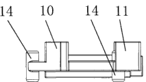
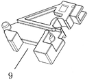
图6是本实用新型活动件的仰视图;Fig. 6 is a bottom view of the movable part of the utility model;
图7是本实用新型活动件的立体图。Fig. 7 is a perspective view of the movable part of the utility model.
【具体实施方式】【Detailed ways】
如图所示,本实用新型所指的一种阻尼器,包括有壳体1,阻尼管2、拉簧3及活动件4,所述壳体1的另一端分叉的设为上壳5和下壳6,所述上壳5和下壳6之间设有夹缝7,所述活动件4卡在夹缝7内,使活动件4能在夹缝7内移动,所述阻尼管2包括有伸缩杆8,所述伸缩杆8的前端与活动件4的中部转动连接;所述拉簧3一端与壳体1的底部相固定,另一端与活动件4的尾部相固定;其中在于活动件4上设有露出壳体1外侧的卡槽9,所述卡槽9设有向上加厚的前卡边10和后卡边11,使推拉门门轨上的拨块不易从卡槽9内脱落,便于推拉门平稳移动。在下壳6上设有导向的滑槽12,在滑槽12的前端设有向内侧弯曲的弧形部13,所述活动件4的前端和后端设有沿导向槽11滑动的导向柱14。As shown in the figure, a damper referred to in the utility model includes a housing 1, a
本实用新型中,所述下壳6上的滑槽12设置在上壳5的外侧。上壳5上位于下壳6的滑槽12弧形部13位置设有与弧形部13形状相同的凹槽15,当活动件4的导向柱14滑动到滑槽12的弧形部13顶端时,使活动件4的前卡边10陷入凹槽15内,此时活动件4的后卡边11露出于壳体1外侧。便于推拉门在移动时,所述门轨上的拨块移动至活动件4的卡槽9内,带动阻尼器工作。In the present invention, the
在本实施例中,在壳体1的一端设有容置腔16,所述阻尼管2设置在容置腔16内。所述容置腔16的外侧设有槽17,所述拉簧3设置在槽17内。所述上壳5和下壳6的端部由螺钉18固定。In this embodiment, an
在本实施例中,所述卡槽9的前卡边10和后卡边11的厚度设置在2.5~15MM之间。In this embodiment, the thickness of the
本实用新型在使用时,由于通过将活动件4的卡槽9的前卡边10和后卡边11向上加厚,从而有效的避免了门轨上的拨块从活动件4的卡槽9内脱落的危害,保证了产品的质量,更有利于它的使用,因此更具有市场竞争能力。When the utility model is in use, because the
Claims (7)
Priority Applications (1)
| Application Number | Priority Date | Filing Date | Title |
|---|---|---|---|
| CN2010201791981U CN201671469U (en) | 2010-04-27 | 2010-04-27 | a damper |
Applications Claiming Priority (1)
| Application Number | Priority Date | Filing Date | Title |
|---|---|---|---|
| CN2010201791981U CN201671469U (en) | 2010-04-27 | 2010-04-27 | a damper |
Publications (1)
| Publication Number | Publication Date |
|---|---|
| CN201671469U true CN201671469U (en) | 2010-12-15 |
Family
ID=43328881
Family Applications (1)
| Application Number | Title | Priority Date | Filing Date |
|---|---|---|---|
| CN2010201791981U Expired - Lifetime CN201671469U (en) | 2010-04-27 | 2010-04-27 | a damper |
Country Status (1)
| Country | Link |
|---|---|
| CN (1) | CN201671469U (en) |
Cited By (4)
| Publication number | Priority date | Publication date | Assignee | Title |
|---|---|---|---|---|
| CN102536027A (en) * | 2012-03-01 | 2012-07-04 | 许姜德 | Damper assembly with self-resetting toggle |
| CN104328964A (en) * | 2014-10-14 | 2015-02-04 | 广东名门锁业有限公司 | Bidirectional buffer pulley mechanism |
| CN105507721A (en) * | 2016-01-19 | 2016-04-20 | 许姜德 | Bi-directional damper device |
| WO2024000727A1 (en) * | 2022-06-29 | 2024-01-04 | 广东欧派克家居智能科技有限公司 | Novel damper for sliding door/window |
-
2010
- 2010-04-27 CN CN2010201791981U patent/CN201671469U/en not_active Expired - Lifetime
Cited By (6)
| Publication number | Priority date | Publication date | Assignee | Title |
|---|---|---|---|---|
| CN102536027A (en) * | 2012-03-01 | 2012-07-04 | 许姜德 | Damper assembly with self-resetting toggle |
| CN104328964A (en) * | 2014-10-14 | 2015-02-04 | 广东名门锁业有限公司 | Bidirectional buffer pulley mechanism |
| CN104328964B (en) * | 2014-10-14 | 2017-01-11 | 广东名门锁业有限公司 | bidirectional buffer pulley mechanism |
| CN105507721A (en) * | 2016-01-19 | 2016-04-20 | 许姜德 | Bi-directional damper device |
| CN105507721B (en) * | 2016-01-19 | 2017-06-27 | 许姜德 | Bidirectional damper device |
| WO2024000727A1 (en) * | 2022-06-29 | 2024-01-04 | 广东欧派克家居智能科技有限公司 | Novel damper for sliding door/window |
Similar Documents
| Publication | Publication Date | Title |
|---|---|---|
| CN201738701U (en) | Anti-wind micro-sound ground absorbing device | |
| CN204920580U (en) | Bounce -back ware bounce -back magnetism bumps | |
| CN202636183U (en) | Buffering mechanism for sliding rail of drawer | |
| CN201738717U (en) | Sliding door anti-bouncing structure with damper | |
| CN204212581U (en) | A kind of multi-door two-way reset snubber | |
| CN114304952A (en) | Novel drawer guide rail | |
| CN203531601U (en) | Buffer self-locking structure of sliding door | |
| CN205250910U (en) | Keyboard mouse drawer | |
| CN201146653Y (en) | A sliding mechanism and a portable electronic product using the sliding mechanism | |
| CN202476986U (en) | Guide rail | |
| CN205502827U (en) | Take buffer that changes extension spring structure back to | |
| CN203515023U (en) | Door lock and switch cabinet provided with same | |
| CN211511111U (en) | Sliding rail | |
| CN205162452U (en) | Furniture drawer's damping anti -disengaging structure | |
| CN201339400Y (en) | Folding type aluminum-alloy doorframe | |
| CN209413617U (en) | A kind of flat sliding door buffer with anti-jump wheel regulatory function | |
| CN201649931U (en) | Track door top wheel | |
| CN205531879U (en) | Modular shell attenuator | |
| CN201425838Y (en) | Sliding invisible CD driver protective door structure of case panel | |
| CN201947579U (en) | Sliding cover device for electronic products | |
| CN201738721U (en) | Closed damper | |
| CN219926883U (en) | Cone double screw rod convenient to maintain | |
| CN204661972U (en) | A kind of full electric baseboard of dual system with bi-motor playback | |
| CN206491536U (en) | A kind of novel buffer | |
| CN216306520U (en) | Operation box connecting shaft convenient to use |
Legal Events
| Date | Code | Title | Description |
|---|---|---|---|
| C14 | Grant of patent or utility model | ||
| GR01 | Patent grant | ||
| CX01 | Expiry of patent term |
Granted publication date: 20101215 |
|
| CX01 | Expiry of patent term |