CN201669479U - A gear hobbing machine fixture - Google Patents

A gear hobbing machine fixture Download PDF

Info

Publication number
CN201669479U
CN201669479U CN2010201056726U CN201020105672U CN201669479U CN 201669479 U CN201669479 U CN 201669479U CN 2010201056726 U CN2010201056726 U CN 2010201056726U CN 201020105672 U CN201020105672 U CN 201020105672U CN 201669479 U CN201669479 U CN 201669479U
Authority
CN
China
Prior art keywords
hobbing machine
gear
mandrel
annular base
gear hobbing
Prior art date
Legal status (The legal status is an assumption and is not a legal conclusion. Google has not performed a legal analysis and makes no representation as to the accuracy of the status listed.)
Expired - Fee Related
Application number
CN2010201056726U
Other languages
Chinese (zh)
Inventor
薛忠坤
Current Assignee (The listed assignees may be inaccurate. Google has not performed a legal analysis and makes no representation or warranty as to the accuracy of the list.)
HEFEISHI HANKUN MACHINERY CO Ltd
Original Assignee
HEFEISHI HANKUN MACHINERY CO Ltd
Priority date (The priority date is an assumption and is not a legal conclusion. Google has not performed a legal analysis and makes no representation as to the accuracy of the date listed.)
Filing date
Publication date
Application filed by HEFEISHI HANKUN MACHINERY CO Ltd filed Critical HEFEISHI HANKUN MACHINERY CO Ltd
Priority to CN2010201056726U priority Critical patent/CN201669479U/en
Application granted granted Critical
Publication of CN201669479U publication Critical patent/CN201669479U/en
Anticipated expiration legal-status Critical
Expired - Fee Related legal-status Critical Current

Links

Images

Classifications

    • Y—GENERAL TAGGING OF NEW TECHNOLOGICAL DEVELOPMENTS; GENERAL TAGGING OF CROSS-SECTIONAL TECHNOLOGIES SPANNING OVER SEVERAL SECTIONS OF THE IPC; TECHNICAL SUBJECTS COVERED BY FORMER USPC CROSS-REFERENCE ART COLLECTIONS [XRACs] AND DIGESTS
    • Y02—TECHNOLOGIES OR APPLICATIONS FOR MITIGATION OR ADAPTATION AGAINST CLIMATE CHANGE
    • Y02P—CLIMATE CHANGE MITIGATION TECHNOLOGIES IN THE PRODUCTION OR PROCESSING OF GOODS
    • Y02P70/00—Climate change mitigation technologies in the production process for final industrial or consumer products
    • Y02P70/10—Greenhouse gas [GHG] capture, material saving, heat recovery or other energy efficient measures, e.g. motor control, characterised by manufacturing processes, e.g. for rolling metal or metal working

Landscapes

  • Gear Processing (AREA)

Abstract

本实用新型公开了一种滚齿机工装夹具,包括有滚齿机,其特征在于:所述滚齿机的回转工作台上固定安装有环形底座,所述环形底座上安装有支座,支座上安装有芯轴,滚齿机悬臂上安装有可升降顶尖,所述顶尖位于芯轴上方,且顶尖顶入芯轴端面的中心孔中;所述滚齿机上刀具夹头前方安装有轴座,滚刀一端安装于刀具夹头上,另一端转动安装于轴座内。本实用新型具有结构简单、使用方便、不需频繁的检测、产品质量稳定,工作效率高等特点,可广泛应用于汽车、摩托车等行业的轮齿加工中。

Figure 201020105672

The utility model discloses a tooling fixture for a gear hobbing machine, which includes a gear hobbing machine, and is characterized in that: an annular base is fixedly installed on the rotary table of the gear hobbing machine, a support is installed on the annular base, and a mandrel is installed on the support , the cantilever of the gear hobbing machine is equipped with a liftable top, the top is located above the mandrel, and the top is pushed into the center hole of the end face of the mandrel; a shaft seat is installed in front of the tool chuck on the hobbing machine, and one end of the hob is installed in the tool holder On the head, the other end is rotated and installed in the shaft seat. The utility model has the characteristics of simple structure, convenient use, no need for frequent detection, stable product quality, high work efficiency, etc., and can be widely used in gear tooth processing in industries such as automobiles and motorcycles.

Figure 201020105672

Description

A kind of gear-hobbing machine frock clamp
Technical field:
The utility model relates generally to field of machining, relates in particular to a kind of gear-hobbing machine frock clamp.
Background technology:
Gear-hobbing machine is most widely used a kind of lathe in the gear cutting machine, machinable straight-tooth, helical gears on gear-hobbing machine, but also machining worm wheel, sprocket wheel etc.; Be applicable in batch, small quantities of single-piece production cylindric spiral gear and worm gear of reaching, still but rolling cut certain parameter scope spends strong, easy to adjust, reliable safety device and automatic lubricating system, as the frock clamp mechanism adopting, as: cutter one end is fixedly mounted on the cutter chuck, the other end does not have fixture, and the mandrel of workpiece suit is also fixed by the heart clamping, and its processing mode is to cutter, the installation requirement of equipment and cutter is higher, and need frequent detection in the process, existence is than mistake, and product quality is not easy to guarantee, the while troublesome poeration, inefficiency has influenced productivity effect.
The utility model content:
The purpose of this utility model is in order to remedy the deficiency of prior art, a kind of gear-hobbing machine frock clamp is provided, solved in the process higher to the required precision of cutter, equipment and cutter, also need frequent detection, product quality is not easy to guarantee, troublesome poeration, problems such as inefficiency have improved productivity effect.
The utility model is achieved through the following technical solutions:
A kind of gear-hobbing machine frock clamp, include gear-hobbing machine, it is characterized in that: be installed with annular base on the rotary table of described gear-hobbing machine, described annular base is provided with the guide groove that the cross section is a T shape, on the described annular base bearing is installed, on the described bearing bolt is installed, described bolt moves in T shape guide groove, realizes bearing position adjustments on annular base; On the described bearing mandrel is installed, described mandrel is a multidiameter, its small end is thread spindle up, described mandrel upper surface is provided with centre bore, it is top on the gear-hobbing machine cantilever of described rotary table top liftable to be installed, the described top mandrel top of being positioned at, and in the top centre bore that heads into the mandrel end face; The described gear-hobbing machine chuck the place ahead of fixing a cutting tool is equipped with axle bed, and hobboing cutter one end is installed on the cutter chuck, and the other end rotates and is installed in the axle bed.
Described a kind of gear-hobbing machine frock clamp, it is characterized in that: the suit processing work that cogs on the described mandrel, and fix by the nut that screws on its small end thread spindle, the described top mandrel top that is positioned at is fixed workpiece, described hobboing cutter is packed into behind the cutter chuck, the other end is fixed by annular sleeve, makes hobboing cutter more stable in process.
The utility model has the advantages that:
The utlity model has simple in structure, easy to use, do not need characteristics such as frequent detection, constant product quality, operating efficiency height, improved productivity effect, can be widely used in the gear teeth processing of industries such as automobile, motorcycle.
Description of drawings:
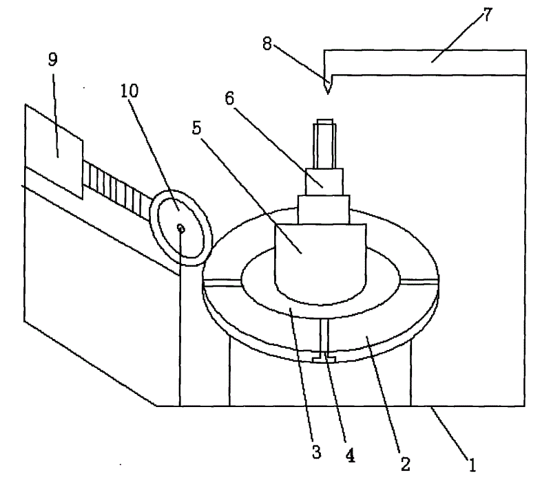
Fig. 1 is the utility model structural representation.
The specific embodiment:
A kind of gear-hobbing machine frock clamp, include gear-hobbing machine 1, be installed with annular base 3 on the rotary table 2 of described gear-hobbing machine 1, described annular base 3 is provided with radially T shape guide groove 4, on the described annular base 3 bearing 5 is installed, on the described bearing 5 bolt is installed, described bolt is motion in the guide groove 4 of T shape in the cross section, on the described bearing 5 mandrel 6 is installed, described mandrel 6 is a multidiameter, and its upper end is small end and is thread spindle, described mandrel 6 upper surfaces are provided with centre bore, liftable top 8, described top 8 is installed on the gear-hobbing machine cantilever 7 of described rotary table 2 tops is positioned at mandrel 6 tops, and top 8 head in the centre bore of mandrel 6 end faces; Described gear-hobbing machine 1 chuck 9 the place aheads of fixing a cutting tool are equipped with axle bed 10, between described axle bed 10 and the cutter chuck 9 hobboing cutter are installed; The suit processing work that cogs on the described mandrel 6, and fix by the nut that screws on its small end thread spindle.Hobboing cutter one end is held on the cutter chuck, and the other end rotates and is installed on the axle bed 10.

Claims (1)

1. gear-hobbing machine frock clamp, include gear-hobbing machine, it is characterized in that: be installed with annular base on the rotary table of described gear-hobbing machine, described annular base is provided with the guide groove that the cross section is a T shape, on the described annular base bearing is installed, on the described bearing bolt is installed, described bolt moves in T shape guide groove, realizes bearing position adjustments on annular base; On the described bearing mandrel is installed, described mandrel is a multidiameter, its small end is thread spindle up, described mandrel upper surface is provided with centre bore, it is top on the gear-hobbing machine cantilever of described rotary table top liftable to be installed, the described top mandrel top of being positioned at, and in the top centre bore that heads into the mandrel end face; The described gear-hobbing machine chuck the place ahead of fixing a cutting tool is equipped with axle bed, and hobboing cutter one end is installed on the cutter chuck, and the other end rotates and is installed in the axle bed.
CN2010201056726U 2010-01-29 2010-01-29 A gear hobbing machine fixture Expired - Fee Related CN201669479U (en)

Priority Applications (1)

Application Number Priority Date Filing Date Title
CN2010201056726U CN201669479U (en) 2010-01-29 2010-01-29 A gear hobbing machine fixture

Applications Claiming Priority (1)

Application Number Priority Date Filing Date Title
CN2010201056726U CN201669479U (en) 2010-01-29 2010-01-29 A gear hobbing machine fixture

Publications (1)

Publication Number Publication Date
CN201669479U true CN201669479U (en) 2010-12-15

Family

ID=43326891

Family Applications (1)

Application Number Title Priority Date Filing Date
CN2010201056726U Expired - Fee Related CN201669479U (en) 2010-01-29 2010-01-29 A gear hobbing machine fixture

Country Status (1)

Country Link
CN (1) CN201669479U (en)

Cited By (2)

* Cited by examiner, † Cited by third party
Publication number Priority date Publication date Assignee Title
CN104308286A (en) * 2014-10-27 2015-01-28 苏州优金金属成型科技有限公司 Gear hobbing machine for machining straight teeth
CN104741705A (en) * 2013-12-31 2015-07-01 天津建筑机械厂 Bulldozer shaft gear tooth grinding special tool

Cited By (2)

* Cited by examiner, † Cited by third party
Publication number Priority date Publication date Assignee Title
CN104741705A (en) * 2013-12-31 2015-07-01 天津建筑机械厂 Bulldozer shaft gear tooth grinding special tool
CN104308286A (en) * 2014-10-27 2015-01-28 苏州优金金属成型科技有限公司 Gear hobbing machine for machining straight teeth

Similar Documents

Publication Publication Date Title
CN103056629B (en) Shaft gear composite processing machine tool
CN104526069B (en) Hobbing-chamfering-burring compound machine tool
CN201913269U (en) Special machine tool for boring
CN201500780U (en) CNC lathe for processing non-circular cross-section parts
CN103600107B (en) Radial feed boring bearing mounting hole inside holes device
CN102500832B (en) Multi-start worm milling machine
CN210132134U (en) A gear shaping device for swinging the inner gear of the hydraulic cylinder
CN103350263B (en) Numerical-control universal thread chasing machine
CN201519811U (en) Four-axis numerical control spiral bevel gear broaching machine
CN204711264U (en) Pass hole slot working boring-machine
CN203579210U (en) Heavy boring and milling machine rotating table
CN102922025B (en) Power cutter frame device capable of being lifted
CN102310329A (en) Double-end numerical control turning and boring mill
CN104476197A (en) Horizontal tooth outer trislot machine
CN203578831U (en) Device for boring inner hole annular groove of bearing installing hole by radial feeding
CN103433791B (en) Transmission device for welding line cutting
CN201693259U (en) Numerical control pipe lathe
CN213916109U (en) Reaming device of variable-frequency electric drive lathe tool
CN204486883U (en) Full-automatic slotter
CN203725815U (en) Biaxial numerical-control boring and scraping rolling machine
CN201357235Y (en) Swiveling tool rest mechanism of double column vertical lathe
CN202742143U (en) Combined numerical control machine tool
CN206084030U (en) Gear -hobbing machine hob head
CN201086208Y (en) Multi-angle processing machine
CN208728681U (en) A kind of Lager ball head processing special tooling

Legal Events

Date Code Title Description
C14 Grant of patent or utility model
GR01 Patent grant
C17 Cessation of patent right
CF01 Termination of patent right due to non-payment of annual fee

Granted publication date: 20101215

Termination date: 20110129