CN201669380U - Core settling jig auxiliary clamp device for cylinder casting - Google Patents
Core settling jig auxiliary clamp device for cylinder casting Download PDFInfo
- Publication number
- CN201669380U CN201669380U CN2010201803828U CN201020180382U CN201669380U CN 201669380 U CN201669380 U CN 201669380U CN 2010201803828 U CN2010201803828 U CN 2010201803828U CN 201020180382 U CN201020180382 U CN 201020180382U CN 201669380 U CN201669380 U CN 201669380U
- Authority
- CN
- China
- Prior art keywords
- lifter plate
- clamp mechanism
- axle bed
- core jig
- core
- Prior art date
- Legal status (The legal status is an assumption and is not a legal conclusion. Google has not performed a legal analysis and makes no representation as to the accuracy of the status listed.)
- Expired - Fee Related
Links
Images
Abstract
A core settling jig auxiliary clamp device for cylinder casting comprises at least one clamp mechanism (1), a drive cylinder (3) and at least one fixing shaft seat (4), wherein the drive cylinder (3) is fixedly arranged on a core settling jig hoisting plate (2), and the fixing shaft seat (4) is fixedly arranged on the core settling jig hoisting plate (2). The upper end of the clamp mechanism (1) is fixedly connected with the output end of the piston rod (3.1) of the drive cylinder (3) by an elevating plate (13). The lower end of the clamp mechanism (1) is rotatingly connected to the shaft of the fixing shaft seat (4). The core settling jig auxiliary clamp device for cylinder casting has the advantages of high work efficiency, low production cost and convenient operation.
Description
Technical field:
The utility model relates to cylinder block Casting Technology field, specifically refers to a kind of cylinder casting core jig auxiliary clamping device.
Background technology:
In cylinder block Casting Technology field, especially produce 4 cylinder bodies of a type in enormous quantities at automatic mo(u)lding line, adopt under the situation of core under the core jig (being core setter), because the core of 4 cylinder bodies of a type is more, length direction will have 11 cores at least, if in core, do not add auxiliary clamping device, only depend on suspension centre on the peripheral core and the overlap joint between core and the core, core setter is difficult to by suspension centre whole cores to be sling smoothly and to be lowered in the casting mold, is easy to cause core to come off in the process of hanging.At present, more domestic casting producers adopt the way of wearing bolt usually, are about to a screw rod that reaches more than 800 millimeter and pass core successively, and core and core are tightened together.Do not only production cost height like this, and inefficiency, very trouble operates.
The utility model content:
The technical problems to be solved in the utility model is: provide a kind of high efficiency, production cost low, easy to operate cylinder casting core jig auxiliary clamping device.
For solving the problems of the technologies described above, the utility model adopts a kind of like this cylinder casting core jig auxiliary clamping device: it comprises at least one clamp mechanism, be fixedly mounted on that core jig plays driving cylinder on the boatswain chair, at least one is fixedly mounted on core jig and plays fixedly axle bed on the boatswain chair; The upper end of described clamp mechanism is fixedly linked through lifter plate and the output that drives cylinder piston rod, the lower end of described clamp mechanism be rotatably connected on fixing axle bed spool on.
Each clamp mechanism comprises at least two clamp arms, the mobile axle bed that at least one is fixedly linked through lifter plate and the output that drives cylinder piston rod; All of each clamp mechanism move and are provided with two waist oblique crank Z holes on the axle bed at least; All clamp arms constitute by oblique arm that is connected as a single entity and upright arm; The upper end of all oblique arms all be fixedly connected on mobile axle bed on the axle that is slidingly matched of corresponding waist oblique crank Z hole, the lower end of all oblique arms intersects and is rotatably connected on the same axis of fixing axle bed; The outer wall of all upright arms is and can filters the shape that the vertical clamping area of reticulum is close to the main body core.
Described clamp mechanism is four, and the mobile axle bed on four clamp mechanism is fixedly connected on the lifter plate jointly, and the center of this lifter plate is fixedly linked with the output that drives cylinder piston rod; Described fixedly axle bed is four, two parallel left ends that are positioned at lifter plate wherein, two other parallel right-hand member that is positioned at lifter plate; Two clamp mechanism in described four clamp mechanism are at two of the lifter plate left end fixedly between the axle bed, and two other is two of lifter plate right-hand member fixedly between the axle bed; Each clamp mechanism is provided with the clamp arm on the same axis that two intersections are rotatably connected on fixing axle bed.
After adopting above structure, the utility model compared with prior art, have the following advantages: owing to set up clamp mechanism, under the drive of cylinder, clamp mechanism is given middle power that makes progress of main body core, preventing effectively that core from coming off downwards in the core process down, has improved operating efficiency greatly, also reduced production cost, it is also very convenient to operate.
As improvement, because described core jig rises between boatswain chair and the lifter plate and is provided with guider, this guider comprises a guide pillar and the guide pin bushing that is slidingly matched with guide pillar, guide pillar is located at core jig and rises on the boatswain chair, guide pin bushing is located on the lifter plate of corresponding guide pillar position, the setting of guider is guaranteed the operation precision of clamp mechanism reliably.
As further improvement, because core jig rises and also is provided with stopping means on the boatswain chair, this stopping means comprises a spacing screw rod and a limited block, the lower surface of spacing screw rod and the upper surface of lifter plate offset, limited block is installed in the lower end of a screw rod, this screw rod is located at core jig and rises on the boatswain chair, and the upper surface of this limited block and the lower surface of lifter plate offset.By regulating the height of spacing screw rod and limited block, control the stroke of lifter plate, thereby the clamping force of clamp mechanism is controlled in the reasonable range like this, both guaranteed that core was successfully sling, do not damage core again.
As further improvement, the vertical clamping area that described main body core filters reticulum is provided with the abrasive rubber skin, can prevent to damage core when having increased frictional force again.
Description of drawings:
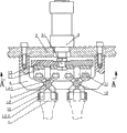
Fig. 1 is installed in the partial schematic sectional view on the core jig when to be the utility model cylinder casting with the core jig auxiliary clamping device be used for core under four cylinder bodies of a type.
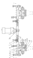
Fig. 2 is the side direction partial schematic sectional view of Fig. 1.
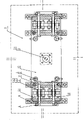
Fig. 3 is that the A-A of Fig. 1 is to partial schematic sectional view.
As shown in the figure: 1, clamp mechanism, 1.1, mobile axle bed, 1.2, clamp arm, 1.2.1, oblique arm 1.2.2, upright arm, 2, core jig plays boatswain chair, 3, drive cylinder, 3.1, drive cylinder piston rod, 4, fixing axle bed, 5, main body core filtration reticulum, 6, guide pillar, 7, guide pin bushing, 8, spacing screw rod, 9, limited block, 10, the abrasive rubber skin, 11, mobile bearing pin, 12, fixed pin shaft, 13, lifter plate.
The specific embodiment:
The utility model is described in further detail below in conjunction with the drawings and specific embodiments.
As shown in Figure 1 to Figure 3, be the cylinder casting core jig auxiliary clamping device that is installed in during core under four cylinder bodies of a type on the core jig, it comprises four clamp mechanism 1, be fixedly mounted on core jig plays on the boatswain chair 2 one and drives fixedly axle bed 4 of cylinder 3 and four.The upper end of four clamp mechanism 1 all is fixedly linked with the output that drives cylinder piston rod 3.1, the lower end of four clamp mechanism 1 all be rotatably connected on fixing axle bed 4 spool on.
Each clamp mechanism 1 comprise two clamp arms 1.2, at least one and drive the mobile axle bed 1.1 that the output of cylinder piston rod 3.1 is fixedly linked.All of each clamp mechanism 1 move and are provided with two waist oblique crank Z holes on the axle bed 1.1 altogether.Two clamp arms 1.2 constitute by oblique arm 1.2.1 that is connected as a single entity and upright arm 1.2.2.Wherein the upper end of all oblique arm 1.2.1 all be fixedly connected on mobile axle bed 1.1 on the axle that is slidingly matched of corresponding waist oblique crank Z hole, this axle is mobile bearing pin 11.The lower end of all oblique arm 1.2.1 intersects and is rotatably connected on the same axis of fixing axle bed 4, and this axle is a fixed pin shaft 12.The outer wall of all upright arm 1.2.2 is and can filters the shape that the vertical clamping area of reticulum 5 is close to the main body core, and this abrasive rubber skin 10 can prevent to damage core again when increasing frictional force.
Mobile axle bed 1.1 on four clamp mechanism 1 is fixedly connected on the square lifter plate of a block length 13 jointly, the center of this lifter plate 13 is fixedly linked with the output that drives cylinder piston rod 3.1, thereby the upper end of realizing clamp mechanism 1 is fixedly linked through lifter plate 13 and the output that drives cylinder piston rod 3.1.Described four fixing two parallel left ends that are positioned at lifter plate 13 in the axle bed 4, two other parallel right-hand member that is positioned at lifter plate 13.And two clamp mechanism 1 in four clamp mechanism 1 are at two of lifter plate 13 left ends fixedly between the axle bed 4, and two other is two of lifter plate 13 right-hand members fixedly between the axle bed 4.Owing to the distance of two clamp mechanism 1 that are positioned at lifter plate 13 left ends or right-hand member is closer, so these two clamp mechanism 1 comprise the mobile axle bed 1.1 that three lower ends with lifter plate 13 are fixedly linked altogether, mobile axle bed 1.1 in the middle of being positioned at is for shared axle bed and be provided with two waist oblique crank Z holes, respectively is provided with a waist oblique crank Z hole and be positioned on the mobile axle bed 1.1 at two ends.
In order to guarantee the operation precision of clamp mechanism 1, core jig rises between boatswain chair 2 and the lifter plate 1.1 and is provided with guider.This guider comprises a guide pillar 6 and the guide pin bushing 7 that is slidingly matched with guide pillar 6, and guide pillar 6 is located at core jig and rises on the boatswain chair 2, and guide pin bushing 7 is located on the lifter plate 13 of corresponding guide pillar 6 positions.
For the clamping force that makes clamp mechanism 1 is controlled in the reasonable range, core can be sling smoothly, do not damage core again, core jig rises and also is provided with stopping means on the boatswain chair 2.This stopping means comprises a spacing screw rod 8 and a limited block 9, the upper surface of the lower surface of this spacing screw rod 8 and lifter plate 1.1 offsets, limited block 9 is installed in the lower end of a screw rod, and this screw rod is located at core jig and rises on the boatswain chair 2, and the lower surface of the upper surface of limited block 9 and lifter plate 1.1 offsets.
During use, drive cylinder piston rod 3.1 drive lifter plates 13 and move up and down, lifter plate 13 drives mobile axle bed 1.1 and moves up and down together.And the clamp arm 1.2 that intersects can be under the drive of mobile bearing pin 11, with fixed pin shaft 12 is that rotate at the center, make the upright arm 1.2.2 of clamp arm 1.2 be close to the main body core and filter the vertical clamping area of reticulum 5 or be separated from, thereby realize the clamping or the action of releasing of clamp mechanism 1 from the vertical clamping area that the main body core filters reticulum 5.In sum, in the process that clamps, clamp mechanism 1 is given middle power that makes progress of main body core, has prevented that effectively core from coming off downwards, has improved operating efficiency greatly, also reduced production cost, and it is very simple and convenient to operate.
Below only just the preferred plan of the utility model embodiment is described, but can not be interpreted as it is restriction claim.The utility model not only is confined to above embodiment, and its concrete structure allows multiple variation., except four,, also can be arranged to different quantity, but be at least one as the quantity of clamp mechanism according to the quantity difference of the cylinder body of producing; The quantity of mobile axle bed also can be carried out the adjustment of quantity as required, but be at least one except one; The quantity of clamp arm also can be carried out the adjustment of quantity as required, but be at least two except two; The structure of clamp mechanism in above embodiment, can also be other structures in addition, as long as can realize that the clamping or the structure of open action are all in protection domain of the present utility model as manipulator.
Claims (6)
1. cylinder casting core jig auxiliary clamping device is characterized in that: it comprises at least one clamp mechanism (1), be fixedly mounted on that core jig plays driving cylinder (3) on the boatswain chair (2), at least one is fixedly mounted on core jig and plays fixedly axle bed (4) on the boatswain chair (2); The upper end of described clamp mechanism (1) is fixedly linked through lifter plate (13) and the output that drives cylinder piston rod (3.1), and the lower end of described clamp mechanism (1) is rotatably connected on the axle of fixing axle bed (4).
2. cylinder casting core jig auxiliary clamping device according to claim 1 is characterized in that: each clamp mechanism (1) comprises at least two clamp arms (1.2), the mobile axle bed (1.1) that at least one is fixedly linked through lifter plate (13) and the output that drives cylinder piston rod (3.1); All of each clamp mechanism (1) move and are provided with two waist oblique crank Z holes on the axle bed (1.1) at least; All clamp arms (1.2) constitute by oblique arm that is connected as a single entity (1.2.1) and upright arm (1.2.2); The upper end of all oblique arms (1.2.1) all is fixedly connected on mobile axle bed (1.1) and goes up on the axle that corresponding waist oblique crank Z hole is slidingly matched, and the lower end intersection of all oblique arms (1.2.1) is rotatably connected on the same axis of fixing axle bed (4); The outer wall of all upright arms (1.2.2) is and can filters the shape that the vertical clamping area of reticulum (5) is close to the main body core.
3. cylinder casting core jig auxiliary clamping device according to claim 2, it is characterized in that: described clamp mechanism (1) is four, mobile axle bed (1.1) on four clamp mechanism (1) is fixedly connected on the lifter plate (13) jointly, and the center of this lifter plate (13) is fixedly linked with the output that drives cylinder piston rod (3.1); Described fixedly axle bed (4) is four, two parallel left ends that are positioned at lifter plate (13) wherein, two other parallel right-hand member that is positioned at lifter plate (13); Two clamp mechanism (1) in described four clamp mechanism (1) are positioned at two of lifter plate (13) left end fixedly between the axle bed (4), and two other two of being positioned at lifter plate (13) right-hand member are fixedly between the axle bed (4); Each clamp mechanism (1) is provided with the clamp arm (1.2) on the same axis that two intersections are rotatably connected on fixing axle bed (4).
4. cylinder casting core jig auxiliary clamping device according to claim 3 is characterized in that: described core jig rises between boatswain chair (2) and the lifter plate (13) and is provided with guider; This guider comprises a guide pillar (6) and the guide pin bushing (7) that is slidingly matched with guide pillar (6), and guide pillar (6) is located at core jig and rises on the boatswain chair (2), and guide pin bushing (7) is located on the lifter plate (13) of corresponding guide pillar (6) position.
5. cylinder casting core jig auxiliary clamping device according to claim 3 is characterized in that: described core jig rises on the boatswain chair (2) and also is provided with stopping means; This stopping means comprises a spacing screw rod (8) and a limited block (9), the upper surface of the lower surface of spacing screw rod (8) and lifter plate (13) offsets, limited block (9) is installed in the lower end of a screw rod, this screw rod is located at core jig and rises on the boatswain chair (2), and the lower surface of upper surface of this limited block (9) and lifter plate (13) offsets.
6. cylinder casting core jig auxiliary clamping device according to claim 3 is characterized in that: the vertical clamping area that described main body core filters reticulum (5) is provided with abrasive rubber skin (10).
Priority Applications (1)
| Application Number | Priority Date | Filing Date | Title |
|---|---|---|---|
| CN2010201803828U CN201669380U (en) | 2010-04-30 | 2010-04-30 | Core settling jig auxiliary clamp device for cylinder casting |
Applications Claiming Priority (1)
| Application Number | Priority Date | Filing Date | Title |
|---|---|---|---|
| CN2010201803828U CN201669380U (en) | 2010-04-30 | 2010-04-30 | Core settling jig auxiliary clamp device for cylinder casting |
Publications (1)
| Publication Number | Publication Date |
|---|---|
| CN201669380U true CN201669380U (en) | 2010-12-15 |
Family
ID=43326792
Family Applications (1)
| Application Number | Title | Priority Date | Filing Date |
|---|---|---|---|
| CN2010201803828U Expired - Fee Related CN201669380U (en) | 2010-04-30 | 2010-04-30 | Core settling jig auxiliary clamp device for cylinder casting |
Country Status (1)
| Country | Link |
|---|---|
| CN (1) | CN201669380U (en) |
Cited By (6)
| Publication number | Priority date | Publication date | Assignee | Title |
|---|---|---|---|---|
| CN102049475A (en) * | 2011-01-19 | 2011-05-11 | 苏州工业园区明志铸造装备有限公司 | Core jig |
| CN102688991A (en) * | 2012-06-14 | 2012-09-26 | 长沙长泰机械股份有限公司 | Three-in-one sealed flexible core setting fixture |
| CN103551525A (en) * | 2013-11-03 | 2014-02-05 | 衢州乐创节能科技有限公司 | Internal mold assembly machine |
| CN105858087A (en) * | 2016-05-31 | 2016-08-17 | 山东科技大学 | Hydraulic brake lock system for automatically tensioning tail of scraper and application of hydraulic brake lock system |
| CN106799468A (en) * | 2016-11-30 | 2017-06-06 | 宁夏共享模具有限公司 | A kind of pneumatic expansion fixture for carrying core |
| CN109014060A (en) * | 2018-06-04 | 2018-12-18 | 苏州勤美达精密机械有限公司 | A kind of laborsaving lower core device and method |
-
2010
- 2010-04-30 CN CN2010201803828U patent/CN201669380U/en not_active Expired - Fee Related
Cited By (7)
| Publication number | Priority date | Publication date | Assignee | Title |
|---|---|---|---|---|
| CN102049475A (en) * | 2011-01-19 | 2011-05-11 | 苏州工业园区明志铸造装备有限公司 | Core jig |
| CN102688991A (en) * | 2012-06-14 | 2012-09-26 | 长沙长泰机械股份有限公司 | Three-in-one sealed flexible core setting fixture |
| CN103551525A (en) * | 2013-11-03 | 2014-02-05 | 衢州乐创节能科技有限公司 | Internal mold assembly machine |
| CN103551525B (en) * | 2013-11-03 | 2015-08-05 | 衢州乐创节能科技有限公司 | A kind of internal mold assembly machine |
| CN105858087A (en) * | 2016-05-31 | 2016-08-17 | 山东科技大学 | Hydraulic brake lock system for automatically tensioning tail of scraper and application of hydraulic brake lock system |
| CN106799468A (en) * | 2016-11-30 | 2017-06-06 | 宁夏共享模具有限公司 | A kind of pneumatic expansion fixture for carrying core |
| CN109014060A (en) * | 2018-06-04 | 2018-12-18 | 苏州勤美达精密机械有限公司 | A kind of laborsaving lower core device and method |
Similar Documents
| Publication | Publication Date | Title |
|---|---|---|
| CN201669380U (en) | Core settling jig auxiliary clamp device for cylinder casting | |
| CN206536220U (en) | A kind of milling machine | |
| CN106926300B (en) | A kind of EPS rotary cutting devices | |
| CN201524770U (en) | Casting suspended core apparatus | |
| CN201808134U (en) | Automatic overturn blank-clamping machine | |
| CN205766103U (en) | A kind of books placement machine people's device | |
| CN205772750U (en) | A kind of hanging apparatus | |
| CN211871239U (en) | Automatic feeding device for machining | |
| CN209261243U (en) | A kind of bricklaying robot lifting device | |
| CN219060938U (en) | Hoisting and supporting device for large-span steel concrete superposed beam | |
| CN206886570U (en) | A kind of crane counterweight adjusting means | |
| CN108840224A (en) | A kind of turnable suspender of concrete precast block | |
| CN214263572U (en) | Mould hoisting device | |
| CN112378649B (en) | Speed reducer fixing device for speed reducer comprehensive experiment table | |
| CN208932797U (en) | A kind of turnable suspender of concrete precast block | |
| CN211895045U (en) | Material clamping mechanical device | |
| CN209737614U (en) | Hydraulic pressure automatic drive's manipulator during retooling | |
| CN209189567U (en) | A kind of lifting tooling platform of vehicle-door edge machine | |
| CN102070074A (en) | Slab clamp and distance device thereof | |
| CN220564112U (en) | Well lid lifting machine convenient to install fast | |
| CN219470695U (en) | Pier body top die supporting device | |
| CN206592713U (en) | A kind of fulcrum bearing | |
| CN208664308U (en) | One kind being capable of quick loading and unloading manipulator | |
| CN216143291U (en) | Pipeline connection auxiliary supporting device for hydraulic engineering construction | |
| CN217711797U (en) | Exempt from building prefab installation mechanism of pouring |
Legal Events
| Date | Code | Title | Description |
|---|---|---|---|
| C14 | Grant of patent or utility model | ||
| GR01 | Patent grant | ||
| CF01 | Termination of patent right due to non-payment of annual fee |
Granted publication date: 20101215 Termination date: 20150430 |
|
| EXPY | Termination of patent right or utility model |