CN201666298U - Locking components - Google Patents
Locking components Download PDFInfo
- Publication number
- CN201666298U CN201666298U CN2010201253315U CN201020125331U CN201666298U CN 201666298 U CN201666298 U CN 201666298U CN 2010201253315 U CN2010201253315 U CN 2010201253315U CN 201020125331 U CN201020125331 U CN 201020125331U CN 201666298 U CN201666298 U CN 201666298U
- Authority
- CN
- China
- Prior art keywords
- sleeve
- locking
- assembly
- locking unit
- section
- Prior art date
- Legal status (The legal status is an assumption and is not a legal conclusion. Google has not performed a legal analysis and makes no representation as to the accuracy of the status listed.)
- Expired - Fee Related
Links
- 230000002452 interceptive effect Effects 0.000 claims description 2
- 238000010586 diagram Methods 0.000 description 2
- 230000000694 effects Effects 0.000 description 2
- 238000000034 method Methods 0.000 description 2
- 239000002131 composite material Substances 0.000 description 1
- 230000008878 coupling Effects 0.000 description 1
- 238000010168 coupling process Methods 0.000 description 1
- 238000005859 coupling reaction Methods 0.000 description 1
- 238000005516 engineering process Methods 0.000 description 1
- 239000007787 solid Substances 0.000 description 1
- 230000000087 stabilizing effect Effects 0.000 description 1
Images

Classifications
-
- F—MECHANICAL ENGINEERING; LIGHTING; HEATING; WEAPONS; BLASTING
- F16—ENGINEERING ELEMENTS AND UNITS; GENERAL MEASURES FOR PRODUCING AND MAINTAINING EFFECTIVE FUNCTIONING OF MACHINES OR INSTALLATIONS; THERMAL INSULATION IN GENERAL
- F16B—DEVICES FOR FASTENING OR SECURING CONSTRUCTIONAL ELEMENTS OR MACHINE PARTS TOGETHER, e.g. NAILS, BOLTS, CIRCLIPS, CLAMPS, CLIPS OR WEDGES; JOINTS OR JOINTING
- F16B5/00—Joining sheets or plates, e.g. panels, to one another or to strips or bars parallel to them
- F16B5/02—Joining sheets or plates, e.g. panels, to one another or to strips or bars parallel to them by means of fastening members using screw-thread
- F16B5/0208—Joining sheets or plates, e.g. panels, to one another or to strips or bars parallel to them by means of fastening members using screw-thread using panel fasteners, i.e. permanent attachments allowing for quick assembly
Landscapes
- Engineering & Computer Science (AREA)
- General Engineering & Computer Science (AREA)
- Mechanical Engineering (AREA)
- Prostheses (AREA)
Abstract
本实用新型提供一种锁固组件,其包含有锁合单元,该锁合单元具有受力部,及连接在受力部一端的锁合部,该受力部另一端设有起子槽,该锁合部具有外螺纹段;以及套筒,该套筒中央设有与外螺纹段相互螺合的内螺纹段。由此,本实用新型锁固组件,可以转动锁合单元,使锁合单元的端面抵靠在套筒的端面,将锁合单元稳定在套筒,因此在进行组装作业时,达到精确地对位结合在其它物体的孔洞、及提升组装效率的目的。
The utility model provides a locking assembly, which includes a locking unit, the locking unit having a force-bearing part, and a locking part connected to one end of the force-bearing part, the other end of the force-bearing part is provided with a screwdriver groove, the locking part has an external thread section; and a sleeve, the center of the sleeve is provided with an internal thread section that is screwed with the external thread section. Therefore, the locking assembly of the utility model can rotate the locking unit so that the end face of the locking unit abuts against the end face of the sleeve, and the locking unit is stabilized in the sleeve, so that when performing assembly operations, the purpose of accurately aligning and combining with the holes of other objects and improving assembly efficiency is achieved.
Description
技术领域technical field
本实用新型关于一种锁固组件,尤指一种可导引套筒精准对位结合在孔洞的锁固组件结构改良者。The utility model relates to a locking component, in particular to a structural improvement of a locking component that can guide a sleeve to be precisely aligned and combined in a hole.
背景技术Background technique
如图1所示,习知的锁固组件包含有一螺丝10、一套盖20及一套筒30;该螺丝10一端具有一受力部101,另一端具有与受力部101连接的螺杆102;该套盖20设在螺丝10受力部101的中空筒,用以包覆该螺丝10;而该套筒30结合在于螺杆102的一端,其端部设有一组接部301。藉此,可以利用该套筒30的组接部301预先组装结合在其它物体50的孔洞501,再利用该螺丝10的螺杆102对应在另一物体60的螺孔601,并以工具对螺丝10的受力部101施以旋转外力,使该螺杆102锁固在螺孔601,藉以完成连接二物体50、60的组合结构。As shown in Figure 1, the known locking assembly includes a screw 10, a cover 20 and a sleeve 30; the screw 10 has a force receiving part 101 at one end, and a screw rod 102 connected with the force receiving part 101 at the other end The sleeve cover 20 is set on the hollow tube of the force-receiving part 101 of the screw 10 to cover the screw 10 ; In this way, the assembly part 301 of the sleeve 30 can be used to pre-assemble the hole 501 combined with the other object 50, and then the screw 102 of the screw 10 can be used to correspond to the screw hole 601 of the other object 60, and the screw 10 can be aligned with a tool. The force-receiving part 101 exerts a rotating external force, so that the screw rod 102 is locked in the screw hole 601, so as to complete the combined structure connecting the two objects 50, 60.
但上述该套筒30套合在螺杆102的结构方式,并未实施稳定住套筒30的设计,导致该套筒30组装在孔洞501的移动过程当中,容易发生松动或晃动现象,如此当撷取整个锁固组件进行组装作业时,将难以准确地对位插入孔洞501,而经常发生套筒30卡置在孔洞501外的问题,影响组装效率甚大。However, the above-mentioned structure of the sleeve 30 fitted on the screw 102 does not implement a design to stabilize the sleeve 30, resulting in the sleeve 30 being assembled in the hole 501 during the movement process, which is prone to loosening or shaking. When the entire locking assembly is assembled, it is difficult to accurately align and insert into the hole 501 , and the problem that the sleeve 30 is stuck outside the hole 501 often occurs, greatly affecting the assembly efficiency.
因此,如何创作出一种锁固组件,以使锁固组件在组装作业时,可以避免上述套筒30卡置在孔洞501上的问题,使套筒30精确地对位结合在其它物体的孔洞,从而提升组装的效率,将是本实用新型所欲积极揭露之处。Therefore, how to create a locking component, so that during the assembly operation of the locking component, the above-mentioned problem that the sleeve 30 is stuck on the hole 501 can be avoided, and the sleeve 30 can be precisely aligned and combined with the holes of other objects , so as to improve the efficiency of assembly, which will be actively disclosed by the utility model.
发明内容Contents of the invention
有鉴于上述习知技术的缺憾,创作人有感其未臻于完善,遂竭其心智悉心研究克服,凭其从事该项产业多年的累积经验,进而研发出一种锁固组件,以期达到锁固组件可以精确地对位结合在其它物体的孔洞、及提升组装效率的目的。In view of the shortcomings of the above-mentioned known technology, the creator felt that it was not perfect, so he exhausted his mind to study and overcome it. Based on his accumulated experience in this industry for many years, he developed a locking component in order to achieve the goal of locking. Solid components can be precisely aligned and combined with holes in other objects, and the purpose of improving assembly efficiency.
本实用新型的主要目的在提供一种锁固组件,其借着锁合单元及套筒结构改良,致使该锁合单元与套筒稳定的结合在一起,不致发生松动或晃动现象,并能利用锁合单元导引套筒对准孔洞进行组装作业,进而达到锁固组件可以精确地对位结合在其它物体的孔洞、及提升组装效率的目的。The main purpose of this utility model is to provide a locking assembly, which improves the structure of the locking unit and the sleeve, so that the locking unit and the sleeve are combined together stably without loosening or shaking, and can be used The guide sleeve of the locking unit is aligned with the holes for assembly, so that the locking components can be precisely aligned and combined with the holes of other objects, and the assembly efficiency is improved.
为达上述目的,本实用新型锁固组件的实施内容包含有:锁合单元,该锁合单元具有受力部,及连接在受力部一端的锁合部,该受力部另一端设有起子槽,该锁合部具有外螺纹段;以及套筒,该套筒中设有与外螺纹段相互螺合的内螺纹段。In order to achieve the above purpose, the implementation content of the locking assembly of the present utility model includes: a locking unit, the locking unit has a force receiving part, and a locking part connected to one end of the force receiving part, and the other end of the force receiving part is provided with The screwdriver groove, the locking part has an external thread section; and the sleeve, an internal thread section screwed with the external thread section is provided in the sleeve.
其中,上述该锁合单元的锁合部包含长杆段,该外螺纹段设置在长杆段的靠近端部;该锁合单元的受力部周围轴向组设有围绕的套盖,该套盖扣接在套筒的一端;该套盖与套筒相邻的端面设有第一扣合部,该套筒与套盖相邻的一端设有与第一扣合部相互干涉的第二扣合部。此外,该套筒的另一端设有组接部,该组接部的周围设有挡止部,该挡止部为直径大于组接部的环体;该组接部周围亦可以设有提供结合在其它物体的第三扣合部,该第三扣合部为断面呈三角形或齿花状的扣环。Wherein, the locking part of the above-mentioned locking unit includes a long rod section, and the external thread section is arranged near the end of the long rod section; the force-bearing part of the locking unit is axially provided with a surrounding sleeve cover, the The cover is fastened to one end of the sleeve; the end surface of the cover adjacent to the sleeve is provided with a first fastening part, and the end of the sleeve adjacent to the cover is provided with a first fastening part which interferes with the first fastening part. Two fastening parts. In addition, the other end of the sleeve is provided with an assembly part, and a stop part is provided around the assembly part, and the stop part is a ring body whose diameter is larger than that of the assembly part; Combined with the third fastening part of other objects, the third fastening part is a buckle with a triangular or flower-shaped section.
附图说明Description of drawings
图1为现有锁固组件的示意图。FIG. 1 is a schematic diagram of a conventional locking assembly.
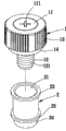
图2为本实用新型锁固组件较佳实施例的分解立体图。Fig. 2 is an exploded perspective view of a preferred embodiment of the locking assembly of the present invention.
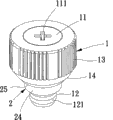
图3为本实用新型锁固组件较佳实施例的组合立体图。Fig. 3 is an assembled perspective view of a preferred embodiment of the locking assembly of the present invention.
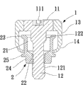
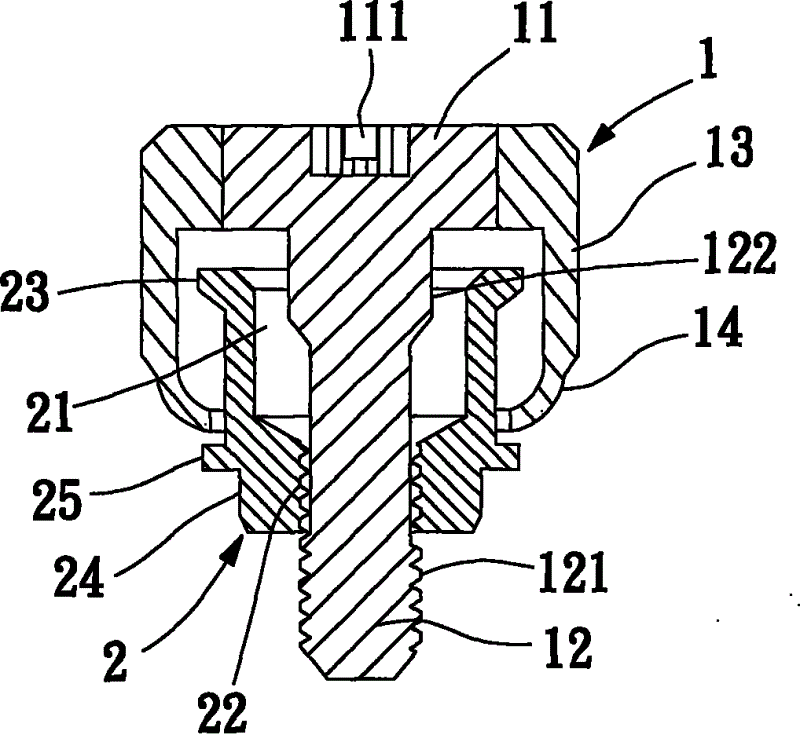
图4为本实用新型锁固组件较佳实施例的组合断面图。Fig. 4 is a combined sectional view of a preferred embodiment of the locking assembly of the present invention.
图5为本实用新型套筒组接部较佳实施例的组合断面图一。Fig. 5 is a
图6为本实用新型套筒组接部较佳实施例的组合断面图二。Fig. 6 is the combined
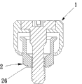
图7为本实用新型套筒第三扣合部较佳实施例的组合断面图一。Fig. 7 is a composite cross-sectional view of a preferred embodiment of the third fastening part of the sleeve of the present invention.
图8为本实用新型套筒第三扣合部较佳实施例的组合断面图二。Fig. 8 is a combined
图9为本实用新型锁固组件另一较佳实施例的组合断面图一。Fig. 9 is a combined
图10为本实用新型锁固组件另一较佳实施例的应用示意图。Fig. 10 is an application schematic diagram of another preferred embodiment of the locking assembly of the present invention.
【主要组件符号说明】[Description of main component symbols]
锁合单元 1 受力部11
起子槽 111 锁合部 12
外螺纹段 121 长杆段 122
套盖 13 第一扣合部 14
套筒 2 通孔 21Sleeve 2 Through
内螺纹段 22 第二扣合部 23
组接部 24 挡止部 25
第三扣合部 26The third fastening
具体实施方式Detailed ways
为充分了解本实用新型的目的、特征及功效,现通过下述具体的实施例,并配合所附的图式,对本实用新型做一详细说明,说明如后:In order to fully understand the purpose, features and effects of the present utility model, the present utility model will be described in detail through the following specific embodiments in conjunction with the attached drawings, as follows:
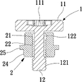
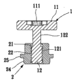
如图2、图3及图4所示,本实用新型的锁固组件,其较佳的实施例包含有:锁合单元1,该锁合单元1设有受力部11,及连接在受力部11一端的锁合部12,该受力部11另一端的端面设有提供螺丝起子等工具耦合的起子槽111,以利用螺丝起子转动锁合单元1,而该锁合部12至少具有外螺纹段121,用以锁合在物体的螺孔;以及套筒2,该套筒2可为中空的圆筒,其中央设有通孔21,该通孔21中设有与外螺纹段121相互螺合的内螺纹段22,从而组成本实用新型的锁固组件。As shown in Figure 2, Figure 3 and Figure 4, the preferred embodiment of the locking assembly of the present invention includes: a
本实用新型锁固组件较佳的实施例更包含:如图4所示,上述该锁合单元1的锁合部12包含有长杆段122,使该外螺纹段121设置在长杆段122的靠近端部,用以锁合在物体的螺孔。该锁合单元1的受力部11周围可以轴向组设有围绕的套盖13,使该套盖13的端部扣接在该套筒2的一端;其扣接在该套筒2的实施例,可在该套盖13与套筒2相邻的端面设有第一扣合部14,并在该套筒2与套盖13相邻的一端设有与第一扣合部14相互干涉的第二扣合部23,如此能防止套筒2与锁合单元1脱离。A preferred embodiment of the locking assembly of the present utility model further includes: as shown in FIG. The near end is used to lock the screw hole in the object. The force-receiving
又如图4、图5及图6所示,该套筒2的另一端设有组接部24,该组接部24可为圆形或其它几何形状直柱状或阶级柱状,用以对位组设在其它物体的孔洞中;该组接部24的周围可以设有挡止部25,该挡止部25直径大于组接部24,如此利用挡止部25与其它物体构成干涉。如图7及图8所示,该组接部24周围亦可以设有提供结合在其它物体的第三扣合部26,该第三扣合部26为图7断面呈三角形或图8齿花状的扣环。另外,如图9及图10所示,本实用新型该锁合单元1的受力部11周围也可以不必实施套盖13及第一扣合部14结构,该套筒2也可以不必实施第二扣合部23,仅利用锁合单元1的外螺纹段121与套筒2的内螺纹段22锁合,也能组成本实用新型的锁固组件。As shown in Fig. 4, Fig. 5 and Fig. 6, the other end of the
本实用新型的锁固组件应用实施时,如图3所示,可以先转动锁合单元1,使锁合单元1的受力部11向套筒2收缩,直到该锁合单元1的端面抵靠在套筒2的端面,并使锁合部12(外螺纹段121)突出套筒2,由此将该锁合单元1稳定在套筒2。因此,当撷取整个锁固组件进行组装作业时,就能避免锁固组件发生晃动现象,先透过锁合单元1的锁合部12(外螺纹段121)伸入其它物体的孔洞作为引导,使套筒2的组接部24可以精准地对位插入其它物体的孔洞中构成组接,如此就能再利用转动锁合单元1,使锁合单元1的锁合部12(外螺纹段121)再锁合在另一物体的螺孔,从而完成连接二物体的组装结构。When the locking assembly of the present utility model is applied and implemented, as shown in Figure 3, the
如上所述,本实用新型完全符合专利三要件:新颖性、进步性和产业上的可利用性。以新颖性和进步性而言,本实用新型借着一锁合单元1及一套筒2结构改良,致使该套筒2与锁合单元1稳定的结合在一起,不致发生松动或晃动现象,并能利用锁合单元1导引套筒2对准孔洞进行组装作业,进而达到锁固组件可以精确地对位结合在其它物体的孔洞、及提升组装效率的效用。就产业上的可利用性而言,利用本实用新型所衍生的产品,当可充分满足目前市场的需求。As mentioned above, the utility model fully complies with the three requirements of the patent: novelty, progress and industrial applicability. In terms of novelty and progress, the utility model improves the structure of a
本实用新型在上文中已以较佳实施例揭露,然熟习本项技术者应理解的是,该实施例仅用于描绘本实用新型,而不应解读为限制本实用新型的范围。应注意的是,举凡与该实施例等效的变化与置换,均应设为涵盖于本实用新型的范畴内。因此,本实用新型的保护范围当以下文的申请专利范围所界定者为准。The present invention has been disclosed above with preferred embodiments, but those skilled in the art should understand that the embodiments are only used to describe the present invention, and should not be construed as limiting the scope of the present invention. It should be noted that all changes and replacements equivalent to this embodiment should be included in the scope of the present utility model. Therefore, the protection scope of the present utility model should be defined by the scope of patent application below.
Claims (6)
Priority Applications (1)
| Application Number | Priority Date | Filing Date | Title |
|---|---|---|---|
| CN2010201253315U CN201666298U (en) | 2010-02-23 | 2010-02-23 | Locking components |
Applications Claiming Priority (1)
| Application Number | Priority Date | Filing Date | Title |
|---|---|---|---|
| CN2010201253315U CN201666298U (en) | 2010-02-23 | 2010-02-23 | Locking components |
Publications (1)
| Publication Number | Publication Date |
|---|---|
| CN201666298U true CN201666298U (en) | 2010-12-08 |
Family
ID=43267258
Family Applications (1)
| Application Number | Title | Priority Date | Filing Date |
|---|---|---|---|
| CN2010201253315U Expired - Fee Related CN201666298U (en) | 2010-02-23 | 2010-02-23 | Locking components |
Country Status (1)
| Country | Link |
|---|---|
| CN (1) | CN201666298U (en) |
Cited By (2)
| Publication number | Priority date | Publication date | Assignee | Title |
|---|---|---|---|---|
| CN102734296A (en) * | 2011-04-12 | 2012-10-17 | 王鼎瑞 | Combined quick assembling device |
| CN103918624A (en) * | 2013-01-15 | 2014-07-16 | 浙江泰普森休闲用品有限公司 | Shelving rod fork base seat and shelving rod fork |
-
2010
- 2010-02-23 CN CN2010201253315U patent/CN201666298U/en not_active Expired - Fee Related
Cited By (3)
| Publication number | Priority date | Publication date | Assignee | Title |
|---|---|---|---|---|
| CN102734296A (en) * | 2011-04-12 | 2012-10-17 | 王鼎瑞 | Combined quick assembling device |
| CN103918624A (en) * | 2013-01-15 | 2014-07-16 | 浙江泰普森休闲用品有限公司 | Shelving rod fork base seat and shelving rod fork |
| CN103918624B (en) * | 2013-01-15 | 2015-12-16 | 浙江泰普森休闲用品有限公司 | Put pike pole pedestal and put pike pole |
Similar Documents
| Publication | Publication Date | Title |
|---|---|---|
| CN204704203U (en) | Combined fastener structure | |
| NZ584654A (en) | Pinned connection with tapered, threaded pin retainers | |
| US8573912B2 (en) | Fastener for attaching a milling cutter body to an adaptor and method of installing same | |
| WO2012102966A3 (en) | Drill string components resistant to jamming | |
| CN102734296A (en) | Combined quick assembling device | |
| KR101610334B1 (en) | Anti loosening screw | |
| WO2008039334A3 (en) | Keylocking threaded insert | |
| CN201855543U (en) | Golf club | |
| CN201636188U (en) | Improved locking device | |
| CN102146952A (en) | Locking components | |
| CN204610454U (en) | Elastic fastening assembly | |
| CN201679822U (en) | Locking assembly | |
| AU2016100452A4 (en) | An embedded ground lock | |
| CN203161777U (en) | Anti-loose safe grounding screw | |
| US20120319955A1 (en) | Computer mouse | |
| CN202943574U (en) | Folding screwdriver | |
| CN204521067U (en) | The fine foot of a kind of carbon with stabilizing components | |
| CN106499706A (en) | A kind of bolt of improved structure | |
| CN201582274U (en) | Locking assembly | |
| CN206473279U (en) | A kind of mop rod positions more firm mop | |
| CN203130694U (en) | A connecting piece for connecting plates | |
| CN206694378U (en) | Stud with head of screw | |
| CN205078579U (en) | One -way screw and special screwdriver | |
| CN204722369U (en) | A kind of electric guitar waistband | |
| US20190162221A1 (en) | Quick drilling screw |
Legal Events
| Date | Code | Title | Description |
|---|---|---|---|
| C14 | Grant of patent or utility model | ||
| GR01 | Patent grant | ||
| C17 | Cessation of patent right | ||
| CF01 | Termination of patent right due to non-payment of annual fee |
Granted publication date: 20101208 Termination date: 20110223 |