CN201663331U - Power adapter - Google Patents
Power adapter Download PDFInfo
- Publication number
- CN201663331U CN201663331U CN2010201564723U CN201020156472U CN201663331U CN 201663331 U CN201663331 U CN 201663331U CN 2010201564723 U CN2010201564723 U CN 2010201564723U CN 201020156472 U CN201020156472 U CN 201020156472U CN 201663331 U CN201663331 U CN 201663331U
- Authority
- CN
- China
- Prior art keywords
- socket
- plug
- power
- main body
- power adapter
- Prior art date
- Legal status (The legal status is an assumption and is not a legal conclusion. Google has not performed a legal analysis and makes no representation as to the accuracy of the status listed.)
- Expired - Fee Related
Links
Images
Abstract
The utility model relates to the technical field of connectors, in particular to a power adapter; the power adapter comprises a main body, wherein one side of the main body is provided with a plug, the main body is also provided with a socket matched with the plug, and the plug is electrically connected with the socket; and as the main body of the power adapter is provided with the plug and the socket simultaneously, a second power adapter can be powered by means of the socket of a first power adapter, thus solving the power supply problem under the condition of fewer external sockets.
Description
Technical field
The utility model relates to the connector technique field, refers in particular to a kind of power-supply adapter.
Background technology
Current, various electrical equipment are multifarious, and are corresponding, and the power connection that various electrical equipment used also has a lot of different types.General power connection, it comprises main part, is equipped with a plug on the main part, plug is inserted supply socket after, promptly can corresponding out-put supply.Well imagine, need set a plurality of supply sockets, can satisfy the use of a plurality of power connections, and in most of occasions, the quantity of supply socket is all fewer, so can satisfy people's demand far from.
The utility model content
The purpose of this utility model is: provide a kind of power-supply adapter at the deficiencies in the prior art, this power-supply adapter structure is simpler, and have portable characteristics, it can use separately, the use that also can a plurality ofly be stitched together can be satisfied the many power supply requirements under a limited number of situations of socket.
For achieving the above object, the utility model is achieved through the following technical solutions:
It comprises main body, and a side of main body has plug, also has socket, plug and socket electric connection with the plug coupling on the main body.
Described plug has conducting terminal, and socket has the jack of pegging graft for conducting terminal.
Described plug sidewalls has fin, and the socket inwall has a plurality of projections, and the gap between a plurality of projections plugs for fin.
Described plug sidewalls has groove, and the socket inwall has positive stop strip, positive stop strip and groove coupling.
Described groove is parallel with conducting terminal.
The beneficial effects of the utility model are: plug and socket is set on main body simultaneously, so just can utilizes the socket of first power-supply adapter to be the power supply of second power supply adapter, thereby solve the power supply supply problem under the few situation of external receptacle quantity.
Description of drawings
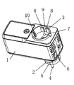
Fig. 1 is a structural representation of the present utility model
Embodiment
Below in conjunction with accompanying drawing the utility model is further described.
See Fig. 1, the utility model power-supply adapter comprises: main body 1, and a side of main body 1 has plug 2, also has the socket 3 that mates with plug 2 on the main body 1, and plug 2 electrically connects with socket 3; Main body shown in the figure 1 is a cuboid, plug 2, socket 3 can be arranged on each side of main body 1, preferable, plug 2, socket 3 are separately positioned on the relative face, for example, when the plug 2 of first power-supply adapter inserted external receptacle downwards, 2 of the plugs of second power supply adapter can insert in the socket 3 of first power-supply adapter, realize the transmission of power supply, very easy to use.
Concrete, described plug 2 has conducting terminal 4, and socket 3 has the jack 7 of pegging graft for conducting terminal 4.
For plug 2 is cooperated with socket 3 closely, described plug 2 sidewalls have fin 5, and socket 3 inwalls have a plurality of projections 8, gap 9 between a plurality of projections 8 plugs for fin 5, when plug 2 was pegged graft with socket 3, fin 5 can insert in the gap 9, thereby plug 2, socket 3 are cooperated closely.
Further, described plug 2 sidewalls have groove 6, and socket 3 inwalls have positive stop strip 10, and positive stop strip 10 and groove 6 couplings can further make plug 2, the stability when socket 3 is pegged graft.
Described groove 6 is parallel with conducting terminal 4, when patchplug, can make groove 6 convenient chimeric with positive stop strip 10 like this.
Certainly, the embodiment of the above, it is preferred embodiments of the present utility model, and unrestricted the utility model practical range, so all equivalences of doing according to the described structure of the utility model claim, feature and principle change or modify, and all should be included in the utility model claim.
Claims (5)
1. power-supply adapter, it is characterized in that: it comprises main body, a side of main body has plug, also has the socket with the plug coupling on the main body, plug and socket electric connection.
2. power-supply adapter according to claim 1 is characterized in that: described plug has conducting terminal, and socket has the jack of pegging graft for conducting terminal.
3. power-supply adapter according to claim 2 is characterized in that: described plug sidewalls has fin, and the socket inwall has a plurality of projections, and the gap between a plurality of projections plugs for fin.
4. according to claim 2 or 3 described power-supply adapters, it is characterized in that: described plug sidewalls has groove, and the socket inwall has positive stop strip, positive stop strip and groove coupling.
5. power-supply adapter according to claim 4 is characterized in that: described groove is parallel with conducting terminal.
Priority Applications (1)
| Application Number | Priority Date | Filing Date | Title |
|---|---|---|---|
| CN2010201564723U CN201663331U (en) | 2010-04-07 | 2010-04-07 | Power adapter |
Applications Claiming Priority (1)
| Application Number | Priority Date | Filing Date | Title |
|---|---|---|---|
| CN2010201564723U CN201663331U (en) | 2010-04-07 | 2010-04-07 | Power adapter |
Publications (1)
| Publication Number | Publication Date |
|---|---|
| CN201663331U true CN201663331U (en) | 2010-12-01 |
Family
ID=43233752
Family Applications (1)
| Application Number | Title | Priority Date | Filing Date |
|---|---|---|---|
| CN2010201564723U Expired - Fee Related CN201663331U (en) | 2010-04-07 | 2010-04-07 | Power adapter |
Country Status (1)
| Country | Link |
|---|---|
| CN (1) | CN201663331U (en) |
Cited By (1)
| Publication number | Priority date | Publication date | Assignee | Title |
|---|---|---|---|---|
| CN107332090A (en) * | 2016-05-20 | 2017-11-07 | 欧普照明股份有限公司 | Adapter, light supply apparatus and lighting apparatus |
-
2010
- 2010-04-07 CN CN2010201564723U patent/CN201663331U/en not_active Expired - Fee Related
Cited By (2)
| Publication number | Priority date | Publication date | Assignee | Title |
|---|---|---|---|---|
| CN107332090A (en) * | 2016-05-20 | 2017-11-07 | 欧普照明股份有限公司 | Adapter, light supply apparatus and lighting apparatus |
| CN107332090B (en) * | 2016-05-20 | 2019-03-19 | 欧普照明股份有限公司 | Adapter, light supply apparatus and lighting apparatus |
Similar Documents
| Publication | Publication Date | Title |
|---|---|---|
| CN203840189U (en) | Adapter | |
| CN201663331U (en) | Power adapter | |
| CN103208687A (en) | Electric connector with cross-shaped sockets | |
| CN102570221B (en) | Combined type plug and socket structure | |
| CN201044269Y (en) | Improved structure of power supply wire | |
| CN203242836U (en) | Waterproof power supply connecting line convenient for connecting and disconnecting | |
| CN202854187U (en) | Plug-pull type electric energy meter | |
| CN201741962U (en) | Extended socket | |
| CN202585997U (en) | Power plug | |
| CN201515132U (en) | Misplug prevention adaptor | |
| CN201674090U (en) | Power plug converter | |
| CN202050085U (en) | Power supply plug with multiple connection function | |
| CN201898254U (en) | Winding structure for power connector | |
| CN203151173U (en) | Extensible socket-type mobile phone charger | |
| CN203085907U (en) | Socket | |
| CN202034656U (en) | Novel electric appliance external power supply connecting equipment | |
| CN204538327U (en) | A kind of patching jack twisted | |
| CN202872130U (en) | Dual-purpose socket | |
| CN203085908U (en) | Modular plug | |
| CN202206004U (en) | Multi-purpose adapter | |
| CN203260855U (en) | Multifunctional USB socket | |
| CN202474365U (en) | Combined socket | |
| CN203180552U (en) | Cell phone charger | |
| CN202454868U (en) | Combined socket | |
| CN201444520U (en) | Integrated extension line of drag-roped socket |
Legal Events
| Date | Code | Title | Description |
|---|---|---|---|
| C14 | Grant of patent or utility model | ||
| GR01 | Patent grant | ||
| DD01 | Delivery of document by public notice | ||
| DD01 | Delivery of document by public notice |
Addressee: Aztech Systems (Dongguan) Co., Ltd. Document name: Notification to Pay the Fees |
|
| CF01 | Termination of patent right due to non-payment of annual fee | ||
| CF01 | Termination of patent right due to non-payment of annual fee |
Granted publication date: 20101201 Termination date: 20170407 |