CN201659181U - Pipe bender - Google Patents
Pipe bender Download PDFInfo
- Publication number
- CN201659181U CN201659181U CN201020165867XU CN201020165867U CN201659181U CN 201659181 U CN201659181 U CN 201659181U CN 201020165867X U CN201020165867X U CN 201020165867XU CN 201020165867 U CN201020165867 U CN 201020165867U CN 201659181 U CN201659181 U CN 201659181U
- Authority
- CN
- China
- Prior art keywords
- roll
- gear
- side frame
- axle sleeve
- roll shaft
- Prior art date
- Legal status (The legal status is an assumption and is not a legal conclusion. Google has not performed a legal analysis and makes no representation as to the accuracy of the status listed.)
- Expired - Fee Related
Links
Images


Abstract
The utility model relates to a pipe bender, comprising a bender body, a driven rolling wheel assembly, a first drive rolling wheel assembly, a second drive rolling wheel assembly, a transmission system assembly, a hydraulic system assembly and an electronic control system assembly; the electronic control system assembly controls the hydraulic system assembly, and the first and second drive rolling wheel assemblies comprises a first side rack, a second side rack, a first roll shaft, a second roll shaft and a first roller and a second roller that are respectively arranged on the first roll shaft and the second roll shaft, the first side rack and the second side rack are respectively articulated with the bender body; the hydraulic system assembly comprises a hydraulic motor, a control valve, an oil pump, a first hydraulic cylinder and a second hydraulic cylinder, the first roller and the second roller are driven to rotate by the transmission system assembly, and the first and the second hydraulic cylinders drive the first side rack and the second side rack to swing around the bender body respectively, the driven rolling wheel assembly comprises a driven roll shaft and a driven roller, the driven roll shaft is arranged on the bender body, and the driven roller is arranged on the driven roll shaft as a rotating body. The pipe bender has the advantages of low manufacturing cost, high bending efficiency and good quality and is suitable for batch production of benders.
Description
Technical field
The utility model relates to section bar processing equipment field, relates in particular to a kind of bending machine.
Background technology
Bending machine does not belong to universal machine, and three kinds of forms are arranged at present, and a kind of is hot bending, and the steel pipe high-frequency heating is bent, and the cost height is applicable to middle large-diameter pipe; The very heavy bending of another kind is suitable for the single-piece production of small-bore pipe; The third method is roasting with fire, utilizes the principle of expanding with heat and contract with cold, and fire is roasting on one side of steel pipe, cooling fast then, steel pipe is just crooked on one side, is applicable to large-diameter pipe, and shortcoming is, crooked position is rough, cause the poor quality, the human and material resources of consumption are too big and efficient that bend is low, uneconomical, single-piece production can, produce in batches inapplicable.
Summary of the invention
Efficient height, the quality that the purpose of this utility model provides a kind of low cost of manufacture, bend is good and be applicable to the bending machine of batch process.
A kind of technical scheme of the present utility model is,
A kind of bending machine, comprise body, a, also comprise the driven wheel assembly that rolls, first initiatively rolls wheel assembly, second initiatively rolls wheel assembly, the transmission system assembly, hydraulic system assembly and electric-control system assembly, the described driven wheel assembly that rolls, first initiatively rolls wheel assembly, second initiatively rolls wheel assembly, the transmission system assembly, hydraulic system assembly and electric-control system assembly are installed on the body, described electric-control system assembly control hydraulic system assembly, b, described first initiatively rolls wheel assembly comprises first bogie side frame, first roll shaft and first roll, described first roll is installed on first roll shaft as rotor, first roll shaft is fixed on first bogie side frame, c, described second initiatively rolls wheel assembly comprises second bogie side frame, second roll shaft and second roll, described second roll is installed on second roll shaft as rotor, second roll shaft is fixed on second bogie side frame, d, described first bogie side frame and second bogie side frame are hinged with body respectively, pin joint is an axis, e, described hydraulic system assembly comprises oil pump, first hydraulic jack, second hydraulic jack, hydraulic motor and control valve, f, described first roll and second roll are by transmission system assembly driven rotary, g, described first hydraulic jack, second hydraulic jack drives first bogie side frame respectively and second bogie side frame is swung around the axis of body, h, the described driven wheel assembly that rolls comprises driven roll shaft and idle roll, driven roll shaft is installed on the body, and idle roll is installed on the driven roll shaft as rotor.
Described transmission system assembly comprises first gear, second gear, the 3rd gear, the 4th gear, the 5th gear and the 6th gear, described first gear and second gears engaged, the 3rd gear is coaxial with second gear, described the 3rd gear and the 4th gears engaged, the 4th gear respectively with the 5th gear and the 6th gears engaged, described the 5th gear drive first roll, the 6th gear drive second roll, described hydraulic motor output shaft and the first gear load.
Described first initiatively rolls wheel assembly also comprises first axle sleeve, first axle sleeve lid, first upper end cover and two clutch shaft bearings, described first axle sleeve is enclosed within outside two clutch shaft bearings, the first axle sleeve periphery flat key load first roll and the 5th gear, two clutch shaft bearings lay respectively at the upper and lower side of the first axle sleeve endoporus, described first axle sleeve lid and the first axle sleeve load, first upper end cover be positioned at first upper end and with its load; Described second initiatively rolls wheel assembly also comprises second axle sleeve, second axle sleeve lid, second upper end cover and two second bearings, described second axle sleeve is enclosed within outside two second bearings, second axle sleeve flat key load second roll and the 6th gear, described second bearing lays respectively at the upper and lower side of the second axle sleeve endoporus, described second axle sleeve lid and the second axle sleeve load, second upper end cover be positioned at second upper end and with its load.
Described first bogie side frame and second bogie side frame all are bending shape, the middle part of first bogie side frame and second bogie side frame all with body on the axis of load hinged, and an end of first bogie side frame and second bogie side frame is hinged with the piston rod of first hydraulic jack, second hydraulic jack respectively, the other end respectively with first roll shaft, the second roll shaft load.
Described hydraulic system assembly also comprises first, second oil cylinder stopping means, described first, second oil cylinder stopping means respectively with first, second hydraulic jack load.
Also has protective cover on the described body.
Described first roll, second roll, idle roll all have circumferential arc groove.
After adopting said structure, owing to also comprise the driven wheel assembly that rolls, first initiatively rolls wheel assembly, second initiatively rolls wheel assembly, the transmission system assembly, hydraulic system assembly and electric-control system assembly, the described driven wheel assembly that rolls, first initiatively rolls wheel assembly, second initiatively rolls wheel assembly, the transmission system assembly, hydraulic system assembly and electric-control system assembly are installed on the body, described electric-control system assembly control hydraulic system assembly, described first initiatively rolls wheel assembly comprises first bogie side frame, first roll shaft and first roll, described first roll is installed on first roll shaft as rotor, first roll shaft is fixed on first bogie side frame, described second initiatively rolls wheel assembly comprises second bogie side frame, second roll shaft and second roll, described second roll is installed on second roll shaft as rotor, second roll shaft is fixed on second bogie side frame, described first bogie side frame and second bogie side frame are hinged with body respectively, pin joint is an axis, described hydraulic system assembly comprises oil pump, first hydraulic jack, second hydraulic jack, hydraulic motor and control valve, described first roll and second roll are by transmission system assembly driven rotary, described first hydraulic jack, second hydraulic jack drives first bogie side frame respectively and second bogie side frame is swung around the axis of body, the described driven wheel assembly that rolls comprises driven roll shaft and idle roll, driven roll shaft is installed on the body, and idle roll is installed on the roll shaft as rotor.The utility model low cost of manufacture, rational in infrastructure, initiatively roll wheel assembly, second by hydraulic system assembly to first and initiatively roll the accurate feeding of wheel assembly, make that the smooth quality of efficient height, flexure plane bend is good, easy to operate and be applicable to the batch process that pipe fitting bends.
Description of drawings
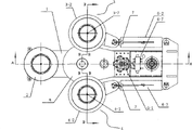
Fig. 1 is a structural representation of the present utility model;
Fig. 2 is the A-A cutaway view of Fig. 1;
Fig. 3 is the B-B cutaway view of Fig. 1;
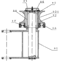
Fig. 4 initiatively rolls wheel assembly 3 schematic diagrames for first of Fig. 1;
Fig. 5 initiatively rolls wheel assembly 4 schematic diagrames for second of Fig. 1;
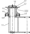
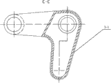
Fig. 6 is the first bogie side frame schematic diagram of Fig. 1;
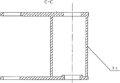
Fig. 7 is the C-C cutaway view of Fig. 6;
Fig. 8 is the D-D cutaway view of Fig. 6;
Fig. 9 is the E-E cutaway view of Fig. 8;
Figure 10 is the F-F cutaway view of Fig. 8;
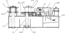
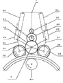
Figure 11 is the operation principle schematic diagram of Fig. 1.
The specific embodiment
Below contrast accompanying drawing,, the utility model made further specifying by the description of the specific embodiment.
Shown in Fig. 1~5, a kind of bending machine, comprise body 1, also comprise the driven wheel assembly 2 that rolls, first initiatively rolls wheel assembly 3, second initiatively rolls wheel assembly 4, transmission system assembly 5, hydraulic system assembly 6 and electric-control system assembly 7, the described driven wheel assembly 2 that rolls, first initiatively rolls wheel assembly 3, second initiatively rolls wheel assembly 4, transmission system assembly 5, hydraulic system assembly 6 and electric-control system assembly 7 are installed on the body 1, described electric-control system assembly 7 control hydraulic system assemblies 6, described first initiatively rolls wheel assembly 3 comprises the first bogie side frame 3-1, the first roll shaft 3-7 and the first roll 3-2, the described first roll 3-2 is installed on the first roll shaft 3-7 as rotor, the first roll shaft 3-7 is fixed on the first bogie side frame 3-1, described second initiatively rolls wheel assembly 4 comprises the second bogie side frame 4-1, the second roll shaft 4-7 and the second roll 4-2, the described second roll 4-2 is installed on the second roll shaft 4-7 as rotor, the second roll shaft 4-7 is fixed on the second bogie side frame 4-1, the described first bogie side frame 3-1 and the second bogie side frame 4-1 are hinged with body 1 respectively, pin joint is an axis 9, described hydraulic system assembly 6 comprises oil pump 6-6, the first hydraulic jack 6-2, the second hydraulic jack 6-3, hydraulic motor 6-1 and control valve 6-7, the described first roll 3-2 and the second roll 4-2 are by transmission system assembly 5 driven rotary, the described first hydraulic jack 6-2, the second hydraulic jack 6-3 drives the first bogie side frame 3-1 respectively and the second bogie side frame 4-1 swings around the axis 9 of body 1, the described driven wheel assembly 2 that rolls comprises driven roll shaft 2-1 and idle roll 2-2, driven roll shaft 2-1 is installed on the body 1, and idle roll 2-2 is installed on the driven roll shaft 2-1 as rotor.
As shown in figure 11, described transmission system assembly 5 comprises the first gear 5-1, the second gear 5-2, the 3rd gear 5-3, the 4th gear 5-4, the 5th gear 5-5 and the 6th gear 5-6, described first gear 5-1 and second gear 5-2 engagement, the 3rd gear 5-3 is coaxial with the second gear 5-2, described the 3rd gear 5-3 and the 4th gear 5-4 engagement, the 4th gear 5-4 meshes with the 5th gear 5-5 and the 6th gear 5-6 respectively, described the 5th gear 5-5 drives the first roll 3-2, the 6th gear 5-6 drives the second roll 4-2, the output shaft of described hydraulic motor 6-1 and the first gear 5-1 load.
Shown in Fig. 4,5, described first initiatively rolls wheel assembly 3 also comprises the first axle sleeve 3-4, first axle sleeve lid 3-6, first upper end cover 3-5 and two clutch shaft bearing 3-3,3-3 ', it is outer that the described first axle sleeve 3-4 is enclosed within two clutch shaft bearing 3-3,3-3 ', the first axle sleeve 3-4 periphery flat key load first roll 3-2 and the 5th gear 5-5, two clutch shaft bearing 3-3,3-3 ' lay respectively at the upper and lower side of the first axle sleeve 3-4 endoporus, described first axle sleeve lid 3-6 and the first axle sleeve 3-4 load, first upper end cover 3-5 be positioned at first upper end and with its load; Described second initiatively rolls wheel assembly 4 also comprises the second axle sleeve 4-4, second axle sleeve lid 4-6, second upper end cover 4-5 and two second bearing 4-3,4-3 ', it is outer that the described second axle sleeve 4-4 is enclosed within two second bearing 4-3,4-3 ', the second axle sleeve 4-4 flat key load second roll 4-2 and the 6th gear 5-6, the described second bearing 4-3,4-3 ' lay respectively at the upper and lower side of the second axle sleeve 4-4 endoporus, described second axle sleeve lid 4-6 and the second axle sleeve 4-4 load, second upper end cover 4-5 be positioned at second upper end and with its load.
Shown in Fig. 6~10, the described first bogie side frame 3-1 and the second bogie side frame 4-1 all are bending shape, the middle part of the first bogie side frame 3-1 and the second bogie side frame 4-1 all with body 1 on the axis 9 of load hinged, and the end of the first bogie side frame 3-1 and the second bogie side frame 4-1 is hinged with the piston rod of the first hydraulic jack 6-2, the second hydraulic jack 6-3 respectively, the other end respectively with the first roll shaft 3-7, the second roll shaft 4-7 load.
Described hydraulic system assembly 6 also comprises first, second oil cylinder stopping means 6-4,6-5, described first, second oil cylinder stopping means 6-4,6-5 respectively with first, second hydraulic jack 6-2,6-3 load.
Also has protective cover 8 on the described body 1.
The described first roll 3-2, the second roll 4-2, idle roll 2-2 all have circumferential arc groove 3-2-1,4-2-1,2-2-1.
Body of the present utility model 1 is welded by steel plate, and the described driven wheel assembly 2, first that rolls initiatively rolls wheel assembly 3, second and initiatively rolls wheel assembly 4, transmission system assembly 5, hydraulic system assembly 6, electric-control system assembly 7 and be installed on the body 1.Idle roll 2-2 has been installed simultaneously, and idle roll 2-2 rotates freely around driven roll shaft 2-1.First, second bogie side frame 3-1,4-1 are that hinge connects with body 1 connecting mode, and pin joint is an axis 9.The first roll 3-2, the second roll 4-2 respectively are installed on first, second bogie side frame 3-1, the 4-1, described the 5th gear 5-5 drives the first roll 3-2, the 6th gear 5-6 drives the second roll 4-2, the described hydraulic motor 6-1 output shaft load first gear 5-1, the first gear 5-1 and second gear 5-2 engagement, the 3rd gear 5-3 is coaxial with the second gear 5-2, around the rotation of axle D point.The 3rd gear 5-3 and the 4th gear 5-4 engagement is meshed with the 5th gear 5-5, the 6th gear 5-6, thereby has finished the tertiary gear transmission, and transmission of power is done equidirectional running to first, second roll 3-2,4-2.The first hydraulic jack 6-2, the second hydraulic jack 6-3 stretch and contract, and promote the first bogie side frame 3-1, the second bogie side frame 4-1 and rotate around pin 9, regulate the horizontal range between the first roll 3-2, the second roll 4-2 and the idle roll 2-2.Internal body is provided with oil pump 6-6, provides energy to hydraulic motor 6-1, the first hydraulic jack 6-2 and the second hydraulic jack 6-3.
The course of work of the present utility model is: 1, power-on starts hydraulic system assembly 6.2, the control valve 6-7 in the control hydraulic system assembly 6, the horizontal range of the first roll 3-2, the second roll 4-2 and idle roll 2-2 is drawn back in the first hydraulic jack 6-2, the second hydraulic jack 6-3 indentation, is convenient to workpiece and enters.3, handle control valve, the first hydraulic jack 6-2, the second hydraulic jack 6-3 stretch out (feeding), and first, second roll 3-2,4-2 and idle roll 2-2 are clamped workpiece.4, handle control valve, the positive and negative rotation of primer fluid pressure motor 6-1 is slowly moved about workpiece according to the order of sequence, and workpiece is rolled repeatedly.5, along with the first hydraulic jack 6-2, the continuous feeding of the second hydraulic jack 6-3, workpiece will produce the curvature radian.The size of curvature is by the first hydraulic jack 6-2, the decision of the second hydraulic jack 6-3 amount of feeding.6, the first oil cylinder stopping means 6-4, the second oil cylinder stopping means 6-5 aim at the control part curvature and establish.
Claims (7)
1. a bending machine comprises body (1), it is characterized in that:
A, also comprise the driven wheel assembly (2) that rolls, first initiatively rolls wheel assembly (3), second initiatively rolls wheel assembly (4), transmission system assembly (5), hydraulic system assembly (6) and electric-control system assembly (7), the described driven wheel assembly (2) that rolls, first initiatively rolls wheel assembly (3), second initiatively rolls wheel assembly (4), transmission system assembly (5), hydraulic system assembly (6) and electric-control system assembly (7) are installed on the body (1), described electric-control system assembly (7) control hydraulic system assembly (6)
B, described first initiatively rolls wheel assembly (3) and comprises first bogie side frame (3-1), first roll shaft (3-7) and first roll (3-2), described first roll (3-2) is installed on first roll shaft (3-7) as rotor, first roll shaft (3-7) is fixed on first bogie side frame (3-1)
C, described second initiatively rolls wheel assembly (4) and comprises second bogie side frame (4-1), second roll shaft (4-7) and second roll (4-2), described second roll (4-2) is installed on second roll shaft (4-7) as rotor, second roll shaft (4-7) is fixed on second bogie side frame (4-1)
D, described first bogie side frame (3-1) and second bogie side frame (4-1) are hinged with body (1) respectively, and pin joint is axis (9),
E, described hydraulic system assembly (6) comprise oil pump (6-6), first hydraulic jack (6-2), second hydraulic jack (6-3), hydraulic motor (6-1) and control valve (6-7),
F, described first roll (3-2) and second roll (4-2) be by transmission system assembly (5) driven rotary,
G, described first hydraulic jack (6-2), second hydraulic jack (6-3) drive first bogie side frame (3-1) respectively and second bogie side frame (4-1) is swung around the axis (9) of body (1),
H, the described driven wheel assembly (2) that rolls comprise driven roll shaft (2-1) and idle roll (2-2), and driven roll shaft (2-1) is installed on the body (1), and idle roll (2-2) is installed on the driven roll shaft (2-1) as rotor.
2. bending machine according to claim 1, it is characterized in that: described transmission system assembly (5) comprises first gear (5-1), second gear (5-2), the 3rd gear (5-3), the 4th gear (5-4), the 5th gear (5-5) and the 6th gear (5-6), described first gear (5-1) and second gear (5-2) engagement, the 3rd gear (5-3) is coaxial with second gear (5-2), described the 3rd gear (5-3) and the 4th gear (5-4) engagement, the 4th gear (5-4) meshes with the 5th gear (5-5) and the 6th gear (5-6) respectively, described the 5th gear (5-5) drives first roll (3-2), the 6th gear (5-6) drives second roll (4-2), the output shaft of described hydraulic motor (6-1) and first gear (5-1) load.
3. bending machine according to claim 2, it is characterized in that: described first initiatively rolls wheel assembly (3) also comprises first axle sleeve (3-4), first axle sleeve lid (3-6), first upper end cover (3-5) and two clutch shaft bearing (3-3,3-3 '), described first axle sleeve (3-4) is enclosed within two clutch shaft bearing (3-3,3-3 ') outside, first axle sleeve (3-4) periphery flat key load first roll (3-2) and the 5th gear (5-5), two clutch shaft bearing (3-3,3-3 ') lays respectively at the upper and lower side of first axle sleeve (3-4) endoporus, described first axle sleeve lid (3-6) and first axle sleeve (3-4) load, first upper end cover (3-5) be positioned at first roll shaft (3-7) upper end and with its load; Described second initiatively rolls wheel assembly (4) also comprises second axle sleeve (4-4), second axle sleeve lid (4-6), second upper end cover (4-5) and two second bearing (4-3,4-3 '), described second axle sleeve (4-4) is enclosed within two second bearing (4-3,4-3 ') outside, second axle sleeve (4-4) periphery flat key load second roll (4-2) and the 6th gear (5-6), the described second bearing (4-3,4-3 ') lays respectively at the upper and lower side of second axle sleeve (4-4) endoporus, described second axle sleeve lid (4-6) and second axle sleeve (4-4) load, second upper end cover (4-5) be positioned at second roll shaft (4-7) upper end and with its load.
4. bending machine according to claim 1, it is characterized in that: described first bogie side frame (3-1) and second bogie side frame (4-1) all are bending shape, the middle part of first bogie side frame (3-1) and second bogie side frame (4-1) is all hinged with the axis (9) of the last load of body (1), and an end of first bogie side frame (3-1) and second bogie side frame (4-1) is hinged with the piston rod of first hydraulic jack (6-2), second hydraulic jack (6-3) respectively, the other end respectively with first roll shaft (3-7), second roll shaft (4-7) load.
5. bending machine according to claim 1, it is characterized in that: described hydraulic system assembly (6) also comprises first, second oil cylinder stopping means (6-4,6-5), described first, second oil cylinder stopping means (6-4,6-5) respectively with first, second hydraulic jack (6-2,6-3) load.
6. bending machine according to claim 1 is characterized in that: also have protective cover (8) on the described body (1).
7. bending machine according to claim 1 is characterized in that: described first roll (3-2), second roll (4-2), idle roll (2-2) all have circumferential arc groove (3-2-1,4-2-1,2-2-1).
Priority Applications (1)
| Application Number | Priority Date | Filing Date | Title |
|---|---|---|---|
| CN201020165867XU CN201659181U (en) | 2010-03-25 | 2010-03-25 | Pipe bender |
Applications Claiming Priority (1)
| Application Number | Priority Date | Filing Date | Title |
|---|---|---|---|
| CN201020165867XU CN201659181U (en) | 2010-03-25 | 2010-03-25 | Pipe bender |
Publications (1)
| Publication Number | Publication Date |
|---|---|
| CN201659181U true CN201659181U (en) | 2010-12-01 |
Family
ID=43229591
Family Applications (1)
| Application Number | Title | Priority Date | Filing Date |
|---|---|---|---|
| CN201020165867XU Expired - Fee Related CN201659181U (en) | 2010-03-25 | 2010-03-25 | Pipe bender |
Country Status (1)
| Country | Link |
|---|---|
| CN (1) | CN201659181U (en) |
Cited By (3)
| Publication number | Priority date | Publication date | Assignee | Title |
|---|---|---|---|---|
| CN102825117A (en) * | 2012-09-10 | 2012-12-19 | 中冶南方武汉钢铁设计研究院有限公司 | Pipe bender precision control method |
| CN104084463A (en) * | 2014-07-17 | 2014-10-08 | 长治市泽洋锻压机械有限公司 | Three-roller fully-driving device of section-bending machine |
| CN109530505A (en) * | 2018-11-20 | 2019-03-29 | 尹明凤 | A kind of full-automatic steel tube bending machine |
-
2010
- 2010-03-25 CN CN201020165867XU patent/CN201659181U/en not_active Expired - Fee Related
Cited By (4)
| Publication number | Priority date | Publication date | Assignee | Title |
|---|---|---|---|---|
| CN102825117A (en) * | 2012-09-10 | 2012-12-19 | 中冶南方武汉钢铁设计研究院有限公司 | Pipe bender precision control method |
| CN102825117B (en) * | 2012-09-10 | 2014-08-20 | 中冶南方武汉钢铁设计研究院有限公司 | Pipe bender precision control method |
| CN104084463A (en) * | 2014-07-17 | 2014-10-08 | 长治市泽洋锻压机械有限公司 | Three-roller fully-driving device of section-bending machine |
| CN109530505A (en) * | 2018-11-20 | 2019-03-29 | 尹明凤 | A kind of full-automatic steel tube bending machine |
Similar Documents
| Publication | Publication Date | Title |
|---|---|---|
| CN201659181U (en) | Pipe bender | |
| CN101406922A (en) | Method for producing grinding ball and rotary cutting and roll forging machine for producing grinding ball | |
| CN101797608A (en) | Pipe bending machine | |
| CN203875272U (en) | Four-hammer-cyclic-loading and low-cycle-fatigue blanking mechanism with 90-degree phase difference | |
| CN103567702B (en) | Flywheel online gear ring quick press mounting method | |
| CN103447358A (en) | T-section steel straightening machine | |
| CN206325965U (en) | A kind of metallic plate processing pressuring flat device | |
| CN208067185U (en) | A kind of continuous folding type steel bar bending apparatus of water conservancy construction variable-angle | |
| CN203221092U (en) | Dual-drive three-roller veneer reeling machine | |
| CN203408983U (en) | Square tube squaring machine | |
| CN201900193U (en) | Roll-in device for drawing part of seamless steel tube | |
| CN206731835U (en) | A kind of uncoiler suitable for different size color steel tiles | |
| CN203944681U (en) | A kind of hydraulic plate bender | |
| CN1544169A (en) | Variable diameter and variable wall steel pipe rolling mill | |
| CN208373856U (en) | A kind of square tube molding machine | |
| CN207806268U (en) | A kind of adjustable type bending mechanism | |
| CN203580162U (en) | High fatigue strength resistance structure based on mechanical press | |
| CN202683699U (en) | Three-roller swing mechanism of hydraulic section-bar bending machine | |
| CN207325685U (en) | A kind of hydraulic pressure corrugation forming machine | |
| CN203484466U (en) | Corrugated boiler flue forming equipment | |
| CN202655516U (en) | Novel numerical control steel bar bending mechanism | |
| CN219233604U (en) | Hydraulic veneer reeling machine | |
| CN204564840U (en) | Veneer reeling machine | |
| CN2220359Y (en) | Four-roller rolling pressed ball shape container lamella and spherical annulus forming machine | |
| CN218425172U (en) | Angle steel bending die |
Legal Events
| Date | Code | Title | Description |
|---|---|---|---|
| C14 | Grant of patent or utility model | ||
| GR01 | Patent grant | ||
| CF01 | Termination of patent right due to non-payment of annual fee | ||
| CF01 | Termination of patent right due to non-payment of annual fee |
Granted publication date: 20101201 Termination date: 20180325 |