CN201646930U - Car door seam fixture - Google Patents
Car door seam fixture Download PDFInfo
- Publication number
- CN201646930U CN201646930U CN201020130242XU CN201020130242U CN201646930U CN 201646930 U CN201646930 U CN 201646930U CN 201020130242X U CN201020130242X U CN 201020130242XU CN 201020130242 U CN201020130242 U CN 201020130242U CN 201646930 U CN201646930 U CN 201646930U
- Authority
- CN
- China
- Prior art keywords
- car door
- seam
- jig frame
- fixture
- grinds
- Prior art date
- Legal status (The legal status is an assumption and is not a legal conclusion. Google has not performed a legal analysis and makes no representation as to the accuracy of the status listed.)
- Expired - Fee Related
Links
Images

Abstract
The utility model relates to a car door seam fixture which comprises an arm frame (1) connected with a manipulator; the lower end of the arm frame (1) is connected with a fixture frame (2) having a shape matched with that of a car door (9); the car door seam fixture is characterized in that the bottom end of the fixture frame (2) is provided with at least two support claws (3); the fixture frame (2) is also provided with a cylinder (4), an output end of which is provided with a cross rod (5); the two ends of the cross rod (5) are provided with pressing clamping jaws (6); seam locating blocks (7) are positioned around the fixture frame (2); and the edges of the seam locating blocks (7) exceed the outline of the car door (9). The car door seam fixture has advantages of simple structure and convenient operation, can effectively ensure the car door to be accurately located in place and a gap between the car door and a car body to be uniform, and has the advantages of reducing the adjusting time of the station, improving the working efficiency and the like.
Description
Technical field
The utility model relates to a kind of simple in structure and ingenious, easy to use, and clamping is reliable, and the car door that especially can regulate gap size between car door and the car body voluntarily grinds the seam anchor clamps.
Background technology
In car production, it is a very important operation that car door is installed on the car body, and when carrying out the installation of car door, the general manipulator that is provided with unit clamp that uses is installed with the car door clamping and after moving to the suitable position of car body; But traditional car door anchor clamps exist many defectives: at first, traditional car door anchor clamps generally adopt sucked type, this anchor clamps that utilize the air pressure principle to carry out clamping, in case in motion process, be subjected to bigger impact, perhaps pneumatic element goes wrong, workpiece just can come off from anchor clamps, causes the damage of workpiece, also threatens operator's safety simultaneously; Secondly, this anchor clamps can't the automatic compensation car door and car body between gap size, can only lean on the operator in installation process, manually to adjust, uneven phenomenon like this will gap; And existing anchor clamps are difficult to guarantee car door and the accurate coplane of car body, not only can have influence on the attractive in appearance of vehicle body, but also bring many problems can for later operation.
Summary of the invention
The utility model is in order to solve existing in prior technology the problems referred to above, provide a kind of simple in structure, easy to operate, can guarantee effectively that the car door accurate positioning puts in place, the slit is even between car door and car body, reduced the adjustment time of this station simultaneously, the car door of increasing work efficiency grinds the seam anchor clamps.
Concrete solution of the present utility model is: a kind of car door grinds the seam anchor clamps, comprise the jib 1 that links to each other with manipulator, be connected with the jig frame 2 that adapts with car door 9 shapes in the lower end of jib 1, it is characterized in that: the bottom of described jig frame 2 is provided with at least two claws 3, on jig frame 2, also be provided with cylinder 4, the mouth of cylinder 4 is provided with cross bar 5, the two ends of cross bar 5 are provided with and press down jaw 6, be provided with around jig frame 2 and grind seam locating piece 7, the edge that grinds seam locating piece 7 all exceeds the outline of car door 9.
The two ends of described jig frame 2 are provided with car body locating wheel 10.
Described jig frame 2 is provided with nest 11, is furnished with locating dowel pin 12 with it mutually.
Described claw 3 is a flexible surface with the outside face that presses down jaw 6.
The utility model is compared with prior art, has following advantage:
This device simple in structure, ingenious, easy to operate, quick adopts fixedly car door of mechanical method of clamping, makes the clamping reliable operation, firm of car door, and what guarantee the car door installation procedure effectively carries out personal safety with the operator smoothly; And in clamping, can adjust the gap width between car door and the car body voluntarily, reduce the adjustment time of this station, enhance productivity; Simultaneously can also guarantee to guarantee accurate coplane between car door and the car body that this device possesses extensive market prospects, very help applying in the art.
Description of drawings
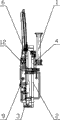
Fig. 1 is a front view of the present utility model.
Fig. 2 is a left view of the present utility model.
The specific embodiment
Below in conjunction with the description of drawings specific embodiment of the present utility model.As shown in Figure 1: a kind of car door grinds the seam anchor clamps, comprises and the jib 1 that can free movable manipulator links to each other, and in the lower end of jib 1, be connected with jig frame 2, the shape of the shape of jig frame 2 and the car door of required installation 9 adapts; Be provided with claw 3 in the bottom of jig frame 2, can not sustain damage in clamping, moving process in order to protect car door, the outside face of claw 3 is provided with the flexible protective layer, and simultaneously in order to guarantee clamping stability, the quantity of claw 3 is at least two; Also be provided with cylinder 4 on jig frame 2, be provided with cross bar 5 at the mouth of cylinder 4, the two ends of cross bar 5 are provided with and press down jaw 6, similarly also are provided with the flexible protective layer at the outside face that presses down jaw 6, and the quantity that presses down jaw 6 in addition also is at least two; Around jig frame 2, be provided with and grind seam locating piece 7, and all outer edges that grinds seam locating piece 7 all exceed the outline part of car door 9; At the two ends of jig frame 2, also be respectively arranged with car body locating wheel 10, at the bottom of the wheel of car body locating wheel 10 with the outside face coplane of car door 9; Also be provided with nest 11 on jig frame 2, matching with nest 11 is provided with locating dowel pin 12.
It is as follows that the car door of the utility model embodiment grinds the working process that stitches anchor clamps: when needs are installed in car door 9 on the car body, manipulator drives the jib 1 that is attached thereto and moves to car door 9 places, and move to car door 9 directions, contact with the bottom of car door 9 until the claw 3 that is positioned at jig frame 2 bottoms, this moment, the mouth of cylinder 4 moved downward, make and press down jaw 6 and be pressed on the framework of car door 9, car door 9 at different model, paired or a plurality of claws 3 and the position relation that presses down between the jaw 6 also can correspondingly change, to adapt to the outline of car door 9, make clamping more firm, firm; At car door by claw 3 with press down when jaw 6 clamps, being arranged on the jig frame 2 seam locating piece 7 that grinds on every side also is on the normal place, and all outer edges that grinds seam locating piece 7 all will exceed the outline part of car door 9, to guarantee in the process of installing, between car door 9 and the car body, gap size in any direction all keeps unified width, has reduced a large amount of adjustment time and work; Therefore grind the width that seam locating piece 7 exceeds car door 9 outlines part, the width that should plant standard slit between vehicle car door and the car body therewith equates; This moment, manipulator can drive jib 1 and car door 9 moves to the car body place, and move to the car body direction, when two car body locating wheels 10 that are positioned at jig frame 2 two ends all contacted with the outside face of car body, the outer surface that car door 9 and car body are described can be carried out erection work in the coplane state; For the ease of the location, on jig frame 2, also be provided with nest 11, the locating dowel pin 12 that matches with it passes nest 11, matches with the knock hole that is arranged on the car body.
Claims (4)
1. a car door grinds the seam anchor clamps, comprise the jib (1) that links to each other with manipulator, be connected with the jig frame (2) that adapts with car door (9) shape in the lower end of jib (1), it is characterized in that: the bottom of described jig frame (2) is provided with at least two claws (3), on jig frame (2), also be provided with cylinder (4), the mouth of cylinder (4) is provided with cross bar (5), the two ends of cross bar (5) are provided with and press down jaw (6), be provided with around jig frame (2) and grind seam locating piece (7), the edge that grinds seam locating piece (7) all exceeds the outline of car door (9).
2. car door according to claim 1 grinds the seam anchor clamps, it is characterized in that: the two ends of described jig frame (2) are provided with car body locating wheel (10).
3. car door according to claim 2 grinds the seam anchor clamps, it is characterized in that: described jig frame (2) is provided with nest (11), is furnished with locating dowel pin (12) with it mutually.
4. car door according to claim 3 grinds the seam anchor clamps, it is characterized in that: described claw (3) and the outside face that presses down jaw (6) are flexible surface.
Priority Applications (1)
| Application Number | Priority Date | Filing Date | Title |
|---|---|---|---|
| CN201020130242XU CN201646930U (en) | 2010-03-15 | 2010-03-15 | Car door seam fixture |
Applications Claiming Priority (1)
| Application Number | Priority Date | Filing Date | Title |
|---|---|---|---|
| CN201020130242XU CN201646930U (en) | 2010-03-15 | 2010-03-15 | Car door seam fixture |
Publications (1)
| Publication Number | Publication Date |
|---|---|
| CN201646930U true CN201646930U (en) | 2010-11-24 |
Family
ID=43112152
Family Applications (1)
| Application Number | Title | Priority Date | Filing Date |
|---|---|---|---|
| CN201020130242XU Expired - Fee Related CN201646930U (en) | 2010-03-15 | 2010-03-15 | Car door seam fixture |
Country Status (1)
| Country | Link |
|---|---|
| CN (1) | CN201646930U (en) |
Cited By (3)
| Publication number | Priority date | Publication date | Assignee | Title |
|---|---|---|---|---|
| CN103158800A (en) * | 2013-03-30 | 2013-06-19 | 长城汽车股份有限公司 | Installation device for auto door seal strip of automobile |
| CN103879474A (en) * | 2012-12-19 | 2014-06-25 | 布罗泽汽车部件制造哈尔施塔特有限公司 | Interface Between A Holding And Balancing Device And A Door Module For A Motor Vehicle Door |
| CN106741308A (en) * | 2016-12-27 | 2017-05-31 | 安徽瑞祥工业有限公司 | A kind of automobile door external formula positioning installation apparatus |
-
2010
- 2010-03-15 CN CN201020130242XU patent/CN201646930U/en not_active Expired - Fee Related
Cited By (5)
| Publication number | Priority date | Publication date | Assignee | Title |
|---|---|---|---|---|
| CN103879474A (en) * | 2012-12-19 | 2014-06-25 | 布罗泽汽车部件制造哈尔施塔特有限公司 | Interface Between A Holding And Balancing Device And A Door Module For A Motor Vehicle Door |
| CN103879474B (en) * | 2012-12-19 | 2016-08-24 | 布罗泽汽车部件制造哈尔施塔特有限公司 | The interface between holding and balancing equipment and door module for motor vehicle door |
| CN103158800A (en) * | 2013-03-30 | 2013-06-19 | 长城汽车股份有限公司 | Installation device for auto door seal strip of automobile |
| CN103158800B (en) * | 2013-03-30 | 2016-01-20 | 长城汽车股份有限公司 | A kind of installation device for auto door seal strip of automobile |
| CN106741308A (en) * | 2016-12-27 | 2017-05-31 | 安徽瑞祥工业有限公司 | A kind of automobile door external formula positioning installation apparatus |
Similar Documents
| Publication | Publication Date | Title |
|---|---|---|
| CN202742103U (en) | Clamp for processing parts | |
| CN102039533A (en) | Special gripper for location on cutting of thimble | |
| CN207593139U (en) | Suitable for the joint welding mold of working at height vehicle carriage | |
| CN201646930U (en) | Car door seam fixture | |
| CN202922474U (en) | Multifunctional clamping device | |
| CN202655837U (en) | Rotary assembly for welding apron board grid of railway vehicle | |
| CN202780614U (en) | Double-side-milling two end face fixtures with clamping range adjustable | |
| CN203214517U (en) | Adhesive sticking mechanism of cooling fin assembly machine | |
| CN209955234U (en) | Multi-gripper injection molding machine manipulator | |
| CN204658030U (en) | Blade groove milling fixture | |
| CN206169702U (en) | Arc work piece upset clamping device for milling | |
| CN102909654B (en) | Clamping device for high-accuracy dual-flat processing of shaft type workpiece | |
| CN201313261Y (en) | Special clamp for wire-cutter milling groove | |
| CN204658032U (en) | Handle of a knife open crotch fine finishining fixture | |
| CN204339380U (en) | A kind of two-way positioning clamping device | |
| CN210254068U (en) | Corn riveting clamp | |
| CN203696533U (en) | Irregular object clamping tool | |
| CN205325271U (en) | Special clamping device of looper frame drilling and tapping | |
| CN202752780U (en) | Motorcycle frame supporting component positioning clamping device | |
| CN202861835U (en) | Pneumatic clamping device | |
| CN203541850U (en) | Laser cutting platform locating device | |
| CN205764846U (en) | A kind of gearbox mount bracket automatic Model Selection is automatically positioned and the most urgent frock | |
| CN206356920U (en) | Clamping device | |
| CN107717789B (en) | Clamp for vernier | |
| CN105500238A (en) | Curved surface self-adaptive fixture based on motor-spring mechanism and working method thereof |
Legal Events
| Date | Code | Title | Description |
|---|---|---|---|
| C14 | Grant of patent or utility model | ||
| GR01 | Patent grant | ||
| C17 | Cessation of patent right | ||
| CF01 | Termination of patent right due to non-payment of annual fee |
Granted publication date: 20101124 Termination date: 20130315 |