CN201633558U - Electric vehicle instrument assembling structure - Google Patents
Electric vehicle instrument assembling structure Download PDFInfo
- Publication number
- CN201633558U CN201633558U CN201020170015XU CN201020170015U CN201633558U CN 201633558 U CN201633558 U CN 201633558U CN 201020170015X U CN201020170015X U CN 201020170015XU CN 201020170015 U CN201020170015 U CN 201020170015U CN 201633558 U CN201633558 U CN 201633558U
- Authority
- CN
- China
- Prior art keywords
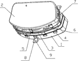
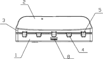
- base
- panel
- rear side
- cover cap
- surrounding edge
- Prior art date
- Legal status (The legal status is an assumption and is not a legal conclusion. Google has not performed a legal analysis and makes no representation as to the accuracy of the status listed.)
- Expired - Lifetime
Links
Images


Abstract
Description
Claims (9)
Priority Applications (1)
| Application Number | Priority Date | Filing Date | Title |
|---|---|---|---|
| CN201020170015XU CN201633558U (en) | 2010-04-23 | 2010-04-23 | Electric vehicle instrument assembling structure |
Applications Claiming Priority (1)
| Application Number | Priority Date | Filing Date | Title |
|---|---|---|---|
| CN201020170015XU CN201633558U (en) | 2010-04-23 | 2010-04-23 | Electric vehicle instrument assembling structure |
Publications (1)
| Publication Number | Publication Date |
|---|---|
| CN201633558U true CN201633558U (en) | 2010-11-17 |
Family
ID=43078038
Family Applications (1)
| Application Number | Title | Priority Date | Filing Date |
|---|---|---|---|
| CN201020170015XU Expired - Lifetime CN201633558U (en) | 2010-04-23 | 2010-04-23 | Electric vehicle instrument assembling structure |
Country Status (1)
| Country | Link |
|---|---|
| CN (1) | CN201633558U (en) |
Cited By (5)
| Publication number | Priority date | Publication date | Assignee | Title |
|---|---|---|---|---|
| CN103158787A (en) * | 2011-12-14 | 2013-06-19 | 苏州万隆汽车零部件股份有限公司 | Vehicle instrument left face plate provided with reserved ports |
| CN103318030A (en) * | 2013-06-06 | 2013-09-25 | 张家港市江南汽车制造有限公司 | Vehicle digital communicating instrument device for extended range electric vehicle |
| CN104943548A (en) * | 2014-03-28 | 2015-09-30 | 铃木株式会社 | Integrated instrument panel mounting structure |
| CN106080197A (en) * | 2016-07-30 | 2016-11-09 | 郑州嘉晨电器有限公司 | Intelligence instrument |
| CN105090336B (en) * | 2014-05-09 | 2018-06-15 | 大陆汽车系统公司 | For the adjustable and flexible damper structure of instrument board |
-
2010
- 2010-04-23 CN CN201020170015XU patent/CN201633558U/en not_active Expired - Lifetime
Cited By (6)
| Publication number | Priority date | Publication date | Assignee | Title |
|---|---|---|---|---|
| CN103158787A (en) * | 2011-12-14 | 2013-06-19 | 苏州万隆汽车零部件股份有限公司 | Vehicle instrument left face plate provided with reserved ports |
| CN103318030A (en) * | 2013-06-06 | 2013-09-25 | 张家港市江南汽车制造有限公司 | Vehicle digital communicating instrument device for extended range electric vehicle |
| CN104943548A (en) * | 2014-03-28 | 2015-09-30 | 铃木株式会社 | Integrated instrument panel mounting structure |
| CN104943548B (en) * | 2014-03-28 | 2017-05-03 | 铃木株式会社 | Integrated instrument panel mounting structure |
| CN105090336B (en) * | 2014-05-09 | 2018-06-15 | 大陆汽车系统公司 | For the adjustable and flexible damper structure of instrument board |
| CN106080197A (en) * | 2016-07-30 | 2016-11-09 | 郑州嘉晨电器有限公司 | Intelligence instrument |
Similar Documents
| Publication | Publication Date | Title |
|---|---|---|
| CN201633558U (en) | Electric vehicle instrument assembling structure | |
| CN108706063B (en) | Battery box for electric bicycle and electric bicycle | |
| CN107801342A (en) | Supporting structure, circuit unit and the device with electric appliance component of electric appliance component | |
| CN206313236U (en) | A kind of socket | |
| CN207897268U (en) | Supporting structure, electric appliance component and the device with electric appliance component of electric appliance component | |
| CN205194618U (en) | Contactor and surge suppressor's mounting structure | |
| CN204801788U (en) | Side wall transition stand template structure | |
| CN203586095U (en) | Dimming support structure of automobile combination headlamp | |
| CN208312285U (en) | A kind of lamp bead installation assembly | |
| CN203165361U (en) | Embedded type electronic display screen structure | |
| CN202147748U (en) | Fixing structure for handle and base of motorcycle steering lamp | |
| CN213414110U (en) | Shell structure and balance car on balance car | |
| CN211364795U (en) | Motorcycle head support | |
| CN205643944U (en) | Liquid crystal display's frame structure and liquid crystal display thereof | |
| CN200943840Y (en) | Improved lamp holder | |
| CN220269263U (en) | Elevation plant light filling device | |
| CN220391414U (en) | Simple type mud guard stay wire quick installation structure | |
| CN202678609U (en) | Module combined type socket | |
| CN209461692U (en) | A kind of three hole bases of quick despatch | |
| CN220325318U (en) | Charging seat for audio-video player and audio-video player assembly | |
| CN210601309U (en) | Classroom lamp | |
| CN214204423U (en) | Concealed installation electric box | |
| CN203378172U (en) | Mounting structure of display box | |
| CN117466111B (en) | Decorative structure for mounting elevator car wall in car | |
| CN210601310U (en) | Classroom lamp |
Legal Events
| Date | Code | Title | Description |
|---|---|---|---|
| C14 | Grant of patent or utility model | ||
| GR01 | Patent grant | ||
| C56 | Change in the name or address of the patentee | ||
| CP02 | Change in the address of a patent holder |
Address after: 310052 No. 415 Xing Xing Road, Hangzhou, Zhejiang, Binjiang District Patentee after: Nebeier Automobile (Hangzhou) Co., Ltd. Address before: Hangzhou City, Zhejiang province Binjiang District 310052 shore road 1180 No. three building 1 floor Patentee before: Nebeier Automobile (Hangzhou) Co., Ltd. Address after: 310052 No. 415 Xing Xing Road, Hangzhou, Zhejiang, Binjiang District Patentee after: Nebeier Automobile (Hangzhou) Co., Ltd. Address before: Hangzhou City, Zhejiang province Binjiang District 310052 shore road 1180 No. three building 1 floor Patentee before: Nebeier Automobile (Hangzhou) Co., Ltd. |
|
| C41 | Transfer of patent application or patent right or utility model | ||
| CB03 | Change of inventor or designer information |
Inventor after: Jin Zheyong Inventor before: Mao Liming Inventor after: Jin Zheyong Inventor before: Mao Liming |
|
| COR | Change of bibliographic data | ||
| TR01 | Transfer of patent right |
Effective date of registration: 20151203 Address after: Hangzhou City, Zhejiang province Binjiang District Puyan streets 310053 ring Hing Road No. 415 1-2 Patentee after: ZOTYE NEW ENERGY AUTOMOBILE CO., LTD. Address before: 310052 No. 415 Xing Xing Road, Hangzhou, Zhejiang, Binjiang District Patentee before: Nebeier Automobile (Hangzhou) Co., Ltd. Effective date of registration: 20151203 Address after: Hangzhou City, Zhejiang province Binjiang District Puyan streets 310053 ring Hing Road No. 415 1-2 Patentee after: ZOTYE NEW ENERGY AUTOMOBILE CO., LTD. Address before: 310052 No. 415 Xing Xing Road, Hangzhou, Zhejiang, Binjiang District Patentee before: Nebeier Automobile (Hangzhou) Co., Ltd. |
|
| DD01 | Delivery of document by public notice |
Addressee: Li Guoping Document name: Notification of Passing Examination on Formalities Addressee: Li Guoping Document name: Notification of Passing Examination on Formalities |
|
| CX01 | Expiry of patent term | ||
| CX01 | Expiry of patent term |
Granted publication date: 20101117 |