Summary of the invention
The purpose of this utility model is to need manually repeatedly to select to cause to use inconvenience at existing double-source gas system, designs a kind of full-automatic double-source gas system.
The technical solution of the utility model is:
A kind of full-automatic double-source gas system, it comprises control circuit board 20, air supply selecting arrangement 21, source of the gas distributes selector valve 22 and double-air-supply nozzle 23, the outlet side that it is characterized in that described air supply selecting arrangement 21 distributes the inlet end of selector valve 22 to link to each other with source of the gas, source of the gas distributes selector valve 22 to be provided with main combustion gas outlet side 24 and ODS outlet side 25, double-air-supply nozzle 23 is installed on the main combustion gas outlet side 24, on source of the gas distribution selector valve 22, first driver 8 of controlling the source of the gas break-make respectively is installed, the 4th driver 14 and second driver 16 and the 3rd driver 28, the first drivers 8 of controlling and select main combustion gas kind of control and selection ODS combustion gas kind, second driver 16, the 3rd driver 28, the 4th driver 13 and air supply selecting arrangement 21 all are electrically connected with control circuit board 20.
Described first driver 8, second driver 16, the 3rd driver 28 and the 4th driver 13 are solenoid valve or motor-driven mechanism.
Described source of the gas distributes selector valve 22 to comprise valve body 1, be provided with air-inlet cavity 2 in the described valve body 1, air distribution cavity 3, ODS outlet passageway 4 and combustion gas outlet passageway 5, one end of air-inlet cavity 2 communicates with the air outlet of air supply selecting arrangement 21, the other end of air-inlet cavity 2 is provided with the air outlet 7 that communicates with air distribution cavity 3, black box 9 is installed on air outlet 7, be provided with higher calorific value ODS air outlet 10 and lower calorific value ODS air outlet 11 in the ODS outlet passageway 4 relatively, on described higher calorific value ODS air outlet 10 that is oppositely arranged and heat supply value ODS air outlet 11, ODS black box 15 be installed into the ODS air feed; Being provided with relatively in the combustion gas outlet passageway 5 is the higher calorific value gas outlet 12 and the fuel gas with low heat value air outlet 13 of main gas supply, on described higher calorific value gas outlet 12 that is oppositely arranged and fuel gas with low heat value air outlet 13 main gas sealing assembly 17 is installed all.
Described air supply selecting arrangement 21 is mainly by dual gas supply pressure maintaining valve 6, automatic selector valve 18 of dual gas supply and full-automatic pressure valve 19 are formed, wherein the automatic selector valve of the inlet end of dual gas supply pressure maintaining valve 6 and dual gas supply 18 corresponding outlet sides communicate, the outlet side of dual gas supply pressure maintaining valve 6 distributes the inlet end of selector valve 22 to link to each other as the outlet side of air supply selecting arrangement 21 with source of the gas, the inlet end of the automatic selector valve 18 of dual gas supply links to each other with the outlet side of full-automatic pressure valve 19, the inlet end of full-automatic pressure valve 19 links to each other with source of the gas, and the pressure signal output terminal of full-automatic pressure valve 19 links to each other with the signal input part of control circuit board 20.
On the described double-air-supply nozzle 23 air door 26 is installed, air door 26 is regulated motor 27 by driving mechanism and air door and is linked to each other.
The beneficial effects of the utility model:
The utility model has been realized selecting corresponding blast tube automatically according to gaseous-pressure by the organic assembling to prior art, has made things convenient for operation widely, and the user only need connect source of the gas and power supply and can use relievedly, need not to carry out loaded down with trivial details operation.
The utility model novel structure is simple, and integrated degree height helps large-scale mass production.
Embodiment
Below in conjunction with drawings and Examples the utility model is further described.
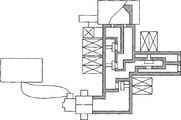
As shown in Figure 1.
A kind of full-automatic double-source gas system, it comprises control circuit board 20 (same as the prior art), air supply selecting arrangement 21, source of the gas distributes selector valve 22 and double-air-supply nozzle 23, the outlet side of air supply selecting arrangement 21 distributes the inlet end of selector valve 22 to link to each other with source of the gas, source of the gas distributes selector valve 22 to be provided with main combustion gas outlet side 24 and ODS outlet side 25, double-air-supply nozzle 23 is installed on the main combustion gas outlet side 24, on double-air-supply nozzle 23, air door 26 can be installed, air door 26 passes through driving mechanism (as gear drive or gear rack, mechanisms such as belt pulley) regulate motor 27 with air door and link to each other, air door is regulated motor 27 and can be installed on the source of the gas distribution selector valve 22; ODS outlet side 25 is provided with two air outlets and links to each other with the higher calorific value inlet end and the lower calorific value inlet end of corresponding dual gas supply ODS gas apparatus respectively.First solenoid valve 8, the control of controlling the source of the gas break-make respectively and the 4th magnet valve 14 of selecting ODS combustion gas kind and control are installed on source of the gas distributes selector valve 22 and select second solenoid valve 16 of main combustion gas kind and the 3rd solenoid valve 28, the first solenoid valves 8, second solenoid valve 16, the 3rd solenoid valve 28 and the 4th solenoid valve 14 and air supply selecting arrangement 21 all are electrically connected with control circuit board 20.Described first solenoid valve 8, second solenoid valve 16, the 3rd solenoid valve 28 and the 4th solenoid valve 14 are gone back the useable electric moter driving structure and are replaced during concrete enforcement, motor rotates and drives corresponding seal bar rotation, one end of seal bar arranges screw thread, seal bar moves shutoff or the unlatching of realization to corresponding air outlet thereby threaded end rotates drive in swivel nut, down together.As shown in Figure 1, 2, 3.
Source of the gas wherein distributes selector valve 22 to comprise valve body 1, be provided with air-inlet cavity 2 in the described valve body 1, air distribution cavity 3, ODS outlet passageway 4 and combustion gas outlet passageway 5, one end of air-inlet cavity 2 communicates with the air outlet of air supply selecting arrangement 21, the other end of air-inlet cavity 2 is provided with the air outlet 7 that communicates with air distribution cavity 3, the black box 9 that is controlled by first solenoid valve 8 is installed on air outlet 7 (to be made up of valve rod and sealing gasket, down together, black box 9 is blocked air outlet 7 among Fig. 1, whole system does not have source of the gas, therefore all there is not source of the gas in ODS and the main gas nozzle, be in closed condition, black box 9 all leaves air outlet 7 among Fig. 2 and Fig. 3, source of the gas can enter in the air distribution cavity 3), be provided with higher calorific value ODS air outlet 10 and lower calorific value ODS air outlet 11 in the ODS outlet passageway 4 relatively into the ODS air feed, on described higher calorific value ODS air outlet 10 that is oppositely arranged and heat supply value ODS air outlet 11, the ODS black box 15 that is controlled by the 4th solenoid valve 14 is installed, these ODS black box 15 shutoff are at higher calorific value gas outlet 12 (Fig. 2, used combustion gas this moment is a fuel gas with low heat value) go up or fuel gas with low heat value air outlet 13 (shown in Figure 3, employed combustion gas this moment is the higher calorific value combustion gas) on; Be provided with relatively in the combustion gas outlet passageway 5 is the higher calorific value gas outlet 12 and the fuel gas with low heat value air outlet 13 of main gas supply, the main gas sealing assembly 17 that is controlled by second solenoid valve 16 and the 3rd solenoid valve 28 is installed on described higher calorific value gas outlet 12 that is oppositely arranged and fuel gas with low heat value air outlet 13, these main gas sealing assembly 17 shutoff are (shown in Figure 2 at higher calorific value gas outlet 12, the combustion gas used this moment is fuel gas with low heat value) go up or fuel gas with low heat value air outlet 13 (shown in Figure 3, employed combustion gas at this moment is the higher calorific value combustion gas) on.
Described air supply selecting arrangement 21 is mainly by dual gas supply pressure maintaining valve 6 (same as the prior art), automatic selector valve 18 of dual gas supply and full-automatic pressure valve 19 are formed, wherein the automatic selector valve of the inlet end of dual gas supply pressure maintaining valve 6 and dual gas supply 18 corresponding outlet sides communicate, the outlet side of dual gas supply pressure maintaining valve 6 distributes the inlet end of selector valve 22 to link to each other as the outlet side of air supply selecting arrangement 21 with source of the gas, the inlet end of the automatic selector valve 18 of dual gas supply links to each other with the outlet side of full-automatic pressure valve 19, the inlet end of full-automatic pressure valve 19 links to each other with source of the gas, and the pressure signal output terminal of full-automatic pressure valve 19 links to each other with the signal input part of control circuit board 20.
The automatic selector valve 18 of dual gas supply can adopt structure shown in Figure 4, it comprises housing 181, be provided with a gas-entered passageway 182 and two outlet passageways 183 in the housing 181,184, two outlet passageways 183, be equipped with the inlet hole 185 that communicates with gas-entered passageway 182 on 184,186, at described inlet hole 185, an I-shaped sealing gasket 187 is installed on 186, the both sides up and down of this I-shaped sealing gasket 187 all with corresponding Returnning spring 188,189 offset and cover on the corresponding inlet hole 185 or inlet hole 186, one end of the vertical edge of I-shaped sealing gasket 187 and lever 1810 is hinged and connected, and the other end of lever 1810 is hinged in the housing 181; Epithelium 1811 is installed above gas-entered passageway 182, spring 1812 is installed on the epithelium 1811, the bottom of epithelium 1811 is connected with the push rod 1813 that driving lever 1810 presses down.
Full-automatic pressure valve 19 can adopt structure shown in Figure 5, it comprises valve body 191 and upper end cap 192, the sense channel 194 that is provided with flat passage 193 and communicates in the described valve body 191 with flat passage 193, in the described sense channel 194 epithelium 195 is arranged, epithelium 195 is fitted between valve body 191 and the upper end cap 192, slide bar 196 is arranged in the cavity of epithelium 195 and upper end cap 192 compositions, one end of slide bar 196 links to each other with epithelium 195 or offsets, because the pressure of combustion gas is bigger, can't work too greatly in order to prevent epithelium 195 distortion, can offset the part gaseous-pressure by the mode that increases extension spring 197 during therefore concrete enforcement, one end of extension spring 197 links to each other with epithelium 195, and the other end links to each other with valve body 191.It is outer continuous or relative with the induction pieces that matches that the other end of slide bar 6 stretches out upper end cap 192.Induction pieces can be sensitive switch during concrete enforcement, a kind of in magnetic switch or the photoelectric sensor switch, when the gas that feeds is the higher calorific value combustion gas, because pressure is bigger, therefore suffered active force is bigger on the epithelium 195, the distance that slide bar 196 stretches out upper end cap 192 is bigger, the switch that the upper end of slide bar 196 can be backed down in the sensitive switch makes it to connect (or disconnection), or the magnet steel that utilizes slide bar 196 tops makes magnetic switch induction action, also the induction light that can utilize stretching out of slide bar 196 to block optoelectronic switch makes the optoelectronic switch action, and control circuit is sensed sensitive switch, can determine the combustion gas of being led to immediately during the action of magnetic switch or photoelectric sensor switch is the higher calorific value combustion gas, then drive corresponding electromagnetism action, make whole gas-fired equipment work in the higher calorific value state.
When the combustion gas that feeds is the higher calorific value combustion gas, open source of the gas and power switch, full-automatic pressure valve 19 is sensed higher pressure at this moment, therefore to signal of control circuit board 20 inputs, control circuit board 20 learns that the combustion gas that is fed is the higher calorific value combustion gas, meanwhile, the automatic selector valve 18 of dual gas supply is also sensed higher pressure, automatically open higher calorific value source of the gas passage, higher calorific value gas source inlet end in the dual gas supply pressure maintaining valve 6 is sent in combustion gas, higher calorific value gas outlet output from dual gas supply pressure maintaining valve 6 after the voltage stabilizing enters the air-inlet cavity 2, the adhesive under the SC sigmal control of control circuit board 20 of first solenoid valve this moment, make black box 9 leave air outlet 7, the higher calorific value combustion gas enters in the air distribution cavity 3, because what full-automatic pressure valve 19 sent is higher calorific value combustion gas signal, therefore control circuit board 20 sends control signal to the 4th solenoid valve 14, and this moment is not because ODS sends signal, therefore, second solenoid valve 16 and the 3rd solenoid valve 28 all are in closed condition, as shown in Figure 6, there is not combustion gas to enter in the nozzle 23, and the 4th solenoid valve 14 moves the sealing gasket shutoff in the black box 15 on lower calorific value ODS air outlet 11, higher calorific value combustion gas in the gas distributing chamber 3 can only be exported in the higher calorific value suction port of ODS burner by higher calorific value ODS air outlet 10, the ODS burner sends 16 actions of Current Control second solenoid valve with the thermocouple heating, second solenoid valve 16 drives black box 12 actions higher calorific value air outlet 12 is opened, the 3rd solenoid valve 28 can not move owing to receive electrical signal, as shown in Figure 3, sealing gasket in the black box 17 will be sealed the lower calorific value air outlet, and higher calorific value air outlet 12 is opened, main combustion gas enters double-air-supply nozzle 23 from higher calorific value air outlet 12 higher calorific value suction port sprays to burner.By remote controller or manually control air door and regulate motor, the air door that its drive is installed on the nozzle rotates the adjustment that realizes the flare color.During concrete enforcement, double-air-supply nozzle 23 also can adopt the claimant first to file not with the double-air-supply nozzle of air door.
Working procedure when the combustion gas that feeds is fuel gas with low heat value is roughly the same, shown in Fig. 6,2.
The utility model does not relate to the part prior art that maybe can adopt all same as the prior art to be realized.