CN201613305U - Cam-type rapid clamp - Google Patents
Cam-type rapid clamp Download PDFInfo
- Publication number
- CN201613305U CN201613305U CN2010201355893U CN201020135589U CN201613305U CN 201613305 U CN201613305 U CN 201613305U CN 2010201355893 U CN2010201355893 U CN 2010201355893U CN 201020135589 U CN201020135589 U CN 201020135589U CN 201613305 U CN201613305 U CN 201613305U
- Authority
- CN
- China
- Prior art keywords
- cam
- pressing plate
- main pressing
- connecting plate
- spanner
- Prior art date
- Legal status (The legal status is an assumption and is not a legal conclusion. Google has not performed a legal analysis and makes no representation as to the accuracy of the status listed.)
- Expired - Fee Related
Links
- 238000003825 pressing Methods 0.000 claims abstract description 55
- 230000013011 mating Effects 0.000 claims description 5
- XEEYBQQBJWHFJM-UHFFFAOYSA-N Iron Chemical compound [Fe] XEEYBQQBJWHFJM-UHFFFAOYSA-N 0.000 abstract 4
- 229910052742 iron Inorganic materials 0.000 abstract 2
- 210000003128 head Anatomy 0.000 description 14
- 244000258271 Galium odoratum Species 0.000 description 4
- 235000008526 Galium odoratum Nutrition 0.000 description 4
- 230000006835 compression Effects 0.000 description 4
- 238000007906 compression Methods 0.000 description 4
- 238000006073 displacement reaction Methods 0.000 description 2
- 230000000694 effects Effects 0.000 description 2
- 238000005516 engineering process Methods 0.000 description 2
- 238000000034 method Methods 0.000 description 2
- 229910000831 Steel Inorganic materials 0.000 description 1
- 238000010009 beating Methods 0.000 description 1
- 238000005452 bending Methods 0.000 description 1
- 230000009286 beneficial effect Effects 0.000 description 1
- 238000010586 diagram Methods 0.000 description 1
- 238000009826 distribution Methods 0.000 description 1
- 239000012467 final product Substances 0.000 description 1
- 238000009434 installation Methods 0.000 description 1
- 238000004519 manufacturing process Methods 0.000 description 1
- 239000000463 material Substances 0.000 description 1
- 230000000149 penetrating effect Effects 0.000 description 1
- 239000010959 steel Substances 0.000 description 1
Images


Landscapes
- Mounting, Exchange, And Manufacturing Of Dies (AREA)
Abstract
The utility model relates to a cam-type rapid clamp, which comprises a connecting plate (1), a small inclined iron wedge (2), a large inclined iron wedge (4) and a main pressing plate device (16). The main pressing plate device (16) comprises a main pressing plate (9), a threaded pin (10), an eccentric wrench (11) and a semi-circular key (14). The pushing/pulling eccentric wrench (11) is arranged to be of 90 DEG, 45 DEG, 30 DEG, and 0 DEG and the like, so as to release or clamp the main pressing plate (9); the lower end of the main pressing plate (9) forms openings A of different sizes under the role of a compressing spring (8). The cam-type rapid clamp facilitates direct installing or fixing of an upper mould (16), so as to realize rapid assembling and disassembling of the upper mould.
Description
Technical field
The utility model relates to a kind of patrix fast fixture of bender.
Background technology
Use at present the fixed form of patrix on the hydraulic numerical control bender, with the patrix of band pocket for the punch head, push between anchor clamps from two ends behind the hook of the pocket for the punch head line-up jig master pressing plate of patrix usually, clamp whole patrix again, special effort when the bigger tulwar mould of clamping.
In the panel beating of the case of the many kinds of processing small batch, cabinet, lid class part, to use undersized diffusing cutter pairing size inevitably, common anchor clamps exist the diffusing cutter of clamping that loosening phenomenon is arranged, and need special pad to be adjusted, and could guarantee that the patrix clamping is firm.
The applicant once proposed a kind of bender rotary type quick-speed jigs in Chinese utility model patent ZL200820155555.3, the applicant is further finding can invent another kind of quick-speed jigs on this basis in the practice.
The utility model content
The purpose of this utility model is to provide and can makes the dismounting of patrix clamping quick and convenient, and the firm bender quick-speed jigs of clamping.
The purpose of this utility model realizes in the following manner:
A kind of bender cam-type quick-speed jigs, be characterized in, comprise connecting plate, main presser device and big wedge, big wedge is fixedlyed connected with connecting plate, main presser device comprises main pressing plate and cam spanner, the middle part of main pressing plate connects the swing support member, the swing support member stretches out from connecting plate, main pressing plate can be the relative connecting plate swing in center with the swing support member, be provided with compressed spring between the lower end of main pressing plate and the connecting plate, this spring makes the opening that is formed for the clamping patrix between the lower end of the lower end of winner's pressing plate and big wedge, cam spanner is rotatably connected to the upper end of main pressing plate, the head of cam spanner is a cam, and the contoured surface of cam contacts with connecting plate, and the rotational angle of cam spanner is associated with the size of described opening.
Described bender cam-type quick-speed jigs, its further characteristics be, cam is the projection with arc surface, and the center of this arc surface and the center of rotation of cam spanner have eccentric throw.
Described bender cam-type quick-speed jigs, its further characteristics be, is inlaid with the hard mold insert in the connecting plate, and the contoured surface of this mold insert and cam contacts.
Described bender cam-type quick-speed jigs, its further characteristics be, the rotary centerline of cam spanner on main pressing plate extends from top to bottom vertically, also provides elongate slots on the main pressing plate, and this elongate slots can be taken in this cam spanner.
Described bender cam-type quick-speed jigs, its further characteristics are, described swing support member is a screw, this screw is fixedlyed connected with big wedge after passing screwed hole on the main pressing plate, the through hole on the connector successively, the mating surface of the screwed hole on the head of this screw and the main pressing plate is that arc-shaped surface and neck size reduce, and the mating surface of the screwed hole of this main pressing plate and the head of screw is a sphere.
The utility model cam-type quick-speed jigs, because of the cam spanner effect, make main pressing plate lower ending opening size, can form a plurality of opening sizes, promptly when eccentric wrench in a predetermined angular position for example 90 when spending, push open by compression spring handle master pressing plate, make the opening size maximum, patrix can directly insert in the main pressing plate, then can spanner shift onto another predetermined angular for example 45 spend to 30 the degree scope, make to tangle patrix, can adjust the position of patrix this moment.During spanner degree of shifting onto zero degree, then compress patrix fully.Regulate the patrix length dimension when needs, can unclamp spanner, will not unload by patrix, directly insert the purpose that the little diffusing cutter patrix that need increase reaches quick-clamping in suitable position.
Description of drawings
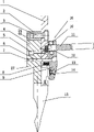
Fig. 1 is the installation diagram of cam-type quick-speed jigs.
Fig. 2 is the stereogram of cam-type quick-speed jigs.
Fig. 3 is anchor clamps connecting plate and big wedge assembling back cutaway view.
Fig. 4 has shown the anchor clamps connecting plate separately, and wherein (a) is the front view of anchor clamps connecting plate, (b) is half sectional view.
Fig. 5 has shown anchor clamps master pressing plate separately, and wherein (a) is anchor clamps master pressing plate front view, (b) is cutaway view.
Fig. 6 is an anchor clamps decenter clutch front view.
The specific embodiment
Referring to Fig. 1 and Fig. 2, cam-type quick-speed jigs of the present utility model comprises: anchor clamps connecting plate 1, little wedge 2, big wedge 4 and main presser device 16.
Referring to Fig. 1 and Fig. 4.Anchor clamps connecting plate 1 is a rectangular slab, and there is the square groove 17 of perforation the upper end, below square groove, is equipped with mounting hole 18 with the level near the plate interposition.Customization soket head cap screw 3 is housed in the mounting hole 18, is used for and the fixedlying connected of little wedge 2.One circular concave surface 19 is arranged in the nearly center of rectangular slab, in to inlay through heat treated cylindrical steel part be mold insert 20, this mold insert 20 is bumped into that back upper surface and plate polish in the plate.The screwed hole 21 that symmetrical distribution is arranged in mold insert 20 both sides.In the bottom of plate five flat spring eyes 22 of bottom ream are arranged, place compression spring 8 in the hole.One group of through hole 23 is arranged above spring eye, is the installing hole of screw 6, and screw 6 passes through hole 23 the described main pressing plate 9 in big wedge 4 and back is connected.
Referring to Fig. 1 and Fig. 5, main presser device 16 is made up of main pressing plate 9, threaded pin 10, decenter clutch 11, woodruff key 14 etc.Main pressing plate 9 is rectangular slabs, and there is mounting hole 27 centre on top, and the right of mounting hole 27 links to each other with square groove 28.Be formed with screw thread pin-and-hole 29 on the top of mounting hole 28, there is screw thread the upper end of screw thread pin-and-hole 29.In mounting hole 27 and square groove 28 decenter clutch 11 is installed, spanner 11 usefulness threaded pins 10 are connected with main pressing plate 9.The lower end of main pressing plate 9 has one to extend inclined-plane 39.Inclined-plane 39 gradients (with respect to vertical plane) are spent to 20 degree scopes 15, have rectangular boss 30 to link up with in the inboard of main pressing plate 9, are used to tangle patrix.The arc groove 31 of one smooth perforation is arranged above boss 30, woodruff key 14 is housed in the groove 31,,, woodruff key 14 is connected on the main pressing plate 9, and makes woodruff key 14 in groove 31, can carry out a spot of flexibly rotation through screw hole 32 with screw 13.Be drilled with two screw holes 33 that are connected with big wedge 4 in the centre of main pressing plate 9, be processed into sphere at the bottom of the hole, main pressing plate 9 can be swung around screw 6.Screw 6 customizes, and is used to connect main pressing plate 9 and big wedge 4, and screw 6 is arc surfaces that R is arranged with the contact surface in main bridge screw hole 33, in the suitable minification in collar position, main pressing plate 9 can be swung around screw 6.
Referring to Fig. 1 and Fig. 6.Decenter clutch 11 is drilled with centre bore 34 for head has the rectangle or the circular rod member of circular arc boss at head, and central hole size cooperates with the threaded pin diameter for basic hole system H8 level and cooperates.There is eccentric throw 35 in the Center-to-Center hole of circular arc boss.Spanner 11 heads are through heat treated, and the middle part of decenter clutch 11 and rear end are adopted to soak and moulded technology and be enclosed with the anti-skidding plastic cover, and spanner can be located when a certain angle position.When decenter clutch 11 usefulness threaded pins 10 are connected with main pressing plate 9, be lined with plain washer 12 at the upper and lower faces of spanner.
After main pressing plate 9 and big wedge 4 usefulness customization soket head cap screw 6 are connected, need to adjust customize soket head cap screw 6 be screwed into depth dimensions to rational position, make main pressing plate 9 can fasten patrix 15 and do not have slippage and become flexible phenomenon.Be screwed into holding screw 7 without a head in the screw hole 26 of big wedge 4 this moment, with screw 6 fastening location.
After the anchor clamps assembling, left and right push-and-pull decenter clutch 11, the circular arc boss of the off-centre of decenter clutch 11 is resisted against on the mold insert 20, because of eccentric throw 35 is arranged, make main pressing plate 9 upper ends along with the rotation of spanner 11 produces different displacement with respect to connecting plate 1, the line that main pressing plate 9 can be shown a plurality of screws 6 this moment greatly is that center line carries out deflection, and main simultaneously pressing plate 9 forms different opening size A in the lower end of plate under the effect of compression spring 8.When decenter clutch 11 was drawn out to 90 degree positions, the displacement minimum of the upper end of main pressing plate 9 was pushed open main pressing plate 9 lower ends by compression spring 8.The opening size A of lower end is maximum, this moment, patrix 16 can directly insert in the anchor clamps master pressing plate 9, can inwardly shift decenter clutch 11 onto 45 then spends to 30 degree scopes, make boss 30 tangle patrix 15, can adjust patrix 16 to suitable fixed position, at last decenter clutch 11 is inwardly shifted onto the end during zero degree, then can lock fixedly patrix fully.Need to regulate the length dimension of patrix, then can unclamp decenter clutch 11, will not unload by patrix, directly insert the little diffusing cutter patrix that needs increase in position, can carry out quick-clamping.
The beneficial effects of the utility model are as follows:
1, on clamping, in the mold process, only need push away, draw decenter clutch, get final product the clamping patrix, save the clamping time.
2, on clamping in the mold process, decenter clutch is in 90 degree positions, and 45 degree can form different opening size A in main pressing plate lower end, convenient dismounting patrix to 30 degree range position. When needs are adjusted the patrix length dimension, only need directly to insert the diffusing cutter patrix of small size, more convenient.
3, these anchor clamps have been reduced the number of the redundancy function part in the situation that satisfies client's instructions for use, and its structure is compact, is convenient to processing and manufacturing, and material is less, and the processing charges cost descends obviously, and cost performance is more reasonable.
Claims (5)
1. bender cam-type quick-speed jigs, it is characterized in that, comprise connecting plate, main presser device and big wedge, big wedge is fixedlyed connected with connecting plate, main presser device comprises main pressing plate and cam spanner, the middle part of main pressing plate connects the swing support member, the swing support member stretches out from connecting plate, main pressing plate can be the relative connecting plate swing in center with the swing support member, be provided with compressed spring between the lower end of main pressing plate and the connecting plate, this spring makes the opening that is formed for the clamping patrix between the lower end of the lower end of winner's pressing plate and big wedge, cam spanner is rotatably connected to the upper end of main pressing plate, the head of cam spanner is a cam, and the contoured surface of cam contacts with connecting plate, and the rotational angle of cam spanner is associated with the size of described opening.
2. bender cam-type quick-speed jigs as claimed in claim 1 is characterized in that cam is the projection with arc surface, and the center of this arc surface and the center of rotation of cam spanner have the cam distance.
3. bender cam-type quick-speed jigs as claimed in claim 1 is characterized in that, is inlaid with the hard mold insert in the connecting plate, and the contoured surface of this mold insert and cam contacts.
4. bender cam-type quick-speed jigs as claimed in claim 1 is characterized in that, the rotary centerline of cam spanner on main pressing plate extends from top to bottom vertically, also provides elongate slots on the main pressing plate, and this elongate slots can be taken in this cam spanner.
5. bender cam-type quick-speed jigs as claimed in claim 1, it is characterized in that, described swing support member is a screw, this screw is fixedlyed connected with big wedge after passing screwed hole on the main pressing plate, the through hole on the connector successively, the mating surface of the screwed hole on the head of this screw and the main pressing plate is that arc-shaped surface and neck size reduce, and the mating surface of the screwed hole of this main pressing plate and the head of screw is a sphere.
Priority Applications (1)
| Application Number | Priority Date | Filing Date | Title |
|---|---|---|---|
| CN2010201355893U CN201613305U (en) | 2010-03-19 | 2010-03-19 | Cam-type rapid clamp |
Applications Claiming Priority (1)
| Application Number | Priority Date | Filing Date | Title |
|---|---|---|---|
| CN2010201355893U CN201613305U (en) | 2010-03-19 | 2010-03-19 | Cam-type rapid clamp |
Publications (1)
| Publication Number | Publication Date |
|---|---|
| CN201613305U true CN201613305U (en) | 2010-10-27 |
Family
ID=42999677
Family Applications (1)
| Application Number | Title | Priority Date | Filing Date |
|---|---|---|---|
| CN2010201355893U Expired - Fee Related CN201613305U (en) | 2010-03-19 | 2010-03-19 | Cam-type rapid clamp |
Country Status (1)
| Country | Link |
|---|---|
| CN (1) | CN201613305U (en) |
Cited By (8)
| Publication number | Priority date | Publication date | Assignee | Title |
|---|---|---|---|---|
| CN102172688A (en) * | 2011-02-25 | 2011-09-07 | 秦皇岛方华埃西姆机械有限公司 | Automatic fixing device for rolling fixture |
| CN103600237A (en) * | 2013-09-24 | 2014-02-26 | 太仓市托达精密模具有限公司 | General quick clamp capable of detaching and installing cutter quickly |
| CN104907405A (en) * | 2015-06-01 | 2015-09-16 | 太仓市托达精密模具有限公司 | Dual-stop quick and convenient tool holder of bending machine |
| CN105458079A (en) * | 2015-12-26 | 2016-04-06 | 山东中际电工装备股份有限公司 | Quick claw stopping and fixing mechanism |
| CN105921624A (en) * | 2016-06-18 | 2016-09-07 | 安徽联盟模具工业股份有限公司 | Compensated upper mould mechanical fast clamping device of bending machine |
| CN106363089A (en) * | 2016-11-30 | 2017-02-01 | 盐城工学院 | Split type upper die clamping device |
| CN109396261A (en) * | 2018-08-30 | 2019-03-01 | 山东万事达建筑钢品股份有限公司 | A kind of bending fast fixture of cutting tool |
| CN109985984A (en) * | 2019-03-27 | 2019-07-09 | 马鞍山市森源模具有限公司 | A kind of main pressing plate of bending machine fast clip |
-
2010
- 2010-03-19 CN CN2010201355893U patent/CN201613305U/en not_active Expired - Fee Related
Cited By (10)
| Publication number | Priority date | Publication date | Assignee | Title |
|---|---|---|---|---|
| CN102172688A (en) * | 2011-02-25 | 2011-09-07 | 秦皇岛方华埃西姆机械有限公司 | Automatic fixing device for rolling fixture |
| CN102172688B (en) * | 2011-02-25 | 2013-08-14 | 秦皇岛方华埃西姆机械有限公司 | Automatic fixing device for rolling fixture |
| CN103600237A (en) * | 2013-09-24 | 2014-02-26 | 太仓市托达精密模具有限公司 | General quick clamp capable of detaching and installing cutter quickly |
| CN104907405A (en) * | 2015-06-01 | 2015-09-16 | 太仓市托达精密模具有限公司 | Dual-stop quick and convenient tool holder of bending machine |
| CN105458079A (en) * | 2015-12-26 | 2016-04-06 | 山东中际电工装备股份有限公司 | Quick claw stopping and fixing mechanism |
| CN105921624A (en) * | 2016-06-18 | 2016-09-07 | 安徽联盟模具工业股份有限公司 | Compensated upper mould mechanical fast clamping device of bending machine |
| CN106363089A (en) * | 2016-11-30 | 2017-02-01 | 盐城工学院 | Split type upper die clamping device |
| CN106363089B (en) * | 2016-11-30 | 2018-06-01 | 盐城工学院 | A kind of split type upper mold clamping device |
| CN109396261A (en) * | 2018-08-30 | 2019-03-01 | 山东万事达建筑钢品股份有限公司 | A kind of bending fast fixture of cutting tool |
| CN109985984A (en) * | 2019-03-27 | 2019-07-09 | 马鞍山市森源模具有限公司 | A kind of main pressing plate of bending machine fast clip |
Similar Documents
| Publication | Publication Date | Title |
|---|---|---|
| CA1251915A (en) | Die clamp | |
| CN205309863U (en) | A jig for processing both sides of a mobile phone shell | |
| CN203622004U (en) | Crankshaft centering fixture | |
| CN201291263Y (en) | Bender rotary quick clamper | |
| CN201183097Y (en) | Bender rapid jig | |
| CN202825327U (en) | Steel pipe clamping block | |
| US7663040B1 (en) | Positioning device for a cymbal | |
| CN105922033A (en) | Step shaft clamping device | |
| CN206953031U (en) | Auto parts production line robot mechanical arm end fast replacing device | |
| CN207629672U (en) | A kind of irregular five gold bullions sleeve pressing machine structure that position can accurately be adjusted | |
| CN104440236A (en) | Motorcycle engine cylinder head milling machine fixing clamper | |
| CN107378735B (en) | A fixing device for a wrench polishing machine | |
| CN205888607U (en) | Clamping device of step shaft | |
| CN209999585U (en) | Injection molding machine mould fixing and adjusting mechanism | |
| CN209793469U (en) | grinding head replacing device and centerless grinding superfinishing machine with same | |
| JPH0647462A (en) | Metallic die attaching device | |
| CN205217669U (en) | Bender cam -type improved generation rapid fixture | |
| CN208600558U (en) | The two-sided quick-speed jigs of bending machine | |
| CN201070055Y (en) | Shoehorn positioning and fastening device | |
| JP2018187648A (en) | Die fitting device | |
| CN212421067U (en) | Fixture for auxiliary assembly of non-standard part of mold | |
| CN203901153U (en) | Locating fixture of brake support | |
| CN216639530U (en) | Leather coining mill is used in leather processing | |
| CN208600559U (en) | Bending machine push button quick-speed jigs | |
| CN208496365U (en) | A kind of clamp system of automobile die production |
Legal Events
| Date | Code | Title | Description |
|---|---|---|---|
| C14 | Grant of patent or utility model | ||
| GR01 | Patent grant | ||
| CF01 | Termination of patent right due to non-payment of annual fee |
Granted publication date: 20101027 Termination date: 20150319 |
|
| EXPY | Termination of patent right or utility model |