CN201601580U - Copper drawing machine - Google Patents
Copper drawing machine Download PDFInfo
- Publication number
- CN201601580U CN201601580U CN201020101198XU CN201020101198U CN201601580U CN 201601580 U CN201601580 U CN 201601580U CN 201020101198X U CN201020101198X U CN 201020101198XU CN 201020101198 U CN201020101198 U CN 201020101198U CN 201601580 U CN201601580 U CN 201601580U
- Authority
- CN
- China
- Prior art keywords
- copper
- hydraulic cylinder
- pincers
- frame
- hinged
- Prior art date
- Legal status (The legal status is an assumption and is not a legal conclusion. Google has not performed a legal analysis and makes no representation as to the accuracy of the status listed.)
- Expired - Fee Related
Links
Images


Abstract
The utility model belongs to the technical field of environment-friendly machinery, and relates to a copper drawing machine, wherein a hydraulic cylinder is horizontally arrange at the upper part of one end of a machine frame, two connecting rods are hinged at the outer end of the piston rod of the hydraulic cylinder, the outer ends of the two connecting rods are hinged with the pliers handle of shear copper drawing pliers capable of moving on the machine frame, a lifting mechanism is arranged at the other end of the machine frame, a positioning plate capable of clamping a motor stator is arranged between the lifting mechanism and the machine frame, the hydraulic cylinder is communicated with an oil pump, an overflow valve and a solenoid valve through an oil pipe, and the operation of the hydraulic cylinder is controlled through a control switch of the solenoid valve. The utility model has the advantages of time and labor conservation, environment friendliness, as well as high recovery efficiency and recovery utilization rate, and can meet the requirement for motor scrap amount treatment. The copper drawing machine is applicable to the recovery of copper coils and motor stators in various models of motors.
Description
Technical field
The utility model belongs to the environmental protection machinery technical field, refers in particular to a kind of copper machine that draws.
Background technology
In mechanization society now, the use of motor is to popularize, because the restriction in the useful life of motor, the spoilage of annual motor increases gradually, copper coil in the motor and motor stator have the value of recycling, scrap the general existing processing by hand of recycling of motor, manual process reclaims the motor of scrapping and exists some shortcomings: one: with extracting tool the coil of motor is dismantled gradually, it is time-consuming effort again, hand disassembly also will remove to burn copper coil with fire, produce the gaseous contamination environment when burning copper coil, organic efficiency is not high, can not satisfy the processing demands of learies; Two: handle by hand unavoidably and cause secondary to destroy to recyclable copper coil and motor stator, the waste recovery utilance reduces.
Summary of the invention
The purpose of this utility model provide a kind of promptly save time and laborsaving, free from environmental pollution, organic efficiency is high, can satisfy demand, recovery utilization rate that the motor learies handles high draw the copper machine.
The purpose of this utility model is achieved in that
Draw the copper machine, upper level at frame one end is provided with hydraulic cylinder, outer end at the piston rod of hydraulic cylinder is hinged with two connecting rods, the outer end of two connecting rods is hinged with the scissor pincers handle of copper pincers that draws that can move on frame, the other end in frame is provided with elevating mechanism, be provided with the location-plate that can block motor stator between elevating mechanism and the frame, hydraulic cylinder is by being communicated with oil pump, overflow valve, electromagnetically operated valve and controlling its action by the control switch of electromagnetically operated valve with oil pipe.
The above-mentioned copper pincers that draw are that to intersect the back at the middle part by two tong arms be that jaw, opposite side are the pincers handles with the hinged side that forms of jointed shaft, are installed with swing arm on a jaw, are provided with flat tooth in the jaw inboard of drawing copper to clamp.
Two connecting rods between the outer end jointed shaft of above-mentioned piston rod and the jointed shaft that draws copper pincers clamp petioliforms and become parallel four-bar linkage with two sections.
The above-mentioned copper pincers that draw can be mobile on the frame: be hinged with sliding bar on the jointed shaft that draws copper to clamp, the both sides of sliding bar tower slidably are connected on the slide rail of frame both sides.
Above-mentioned location-plate is: symmetry is hung with location-plate on the other end of frame, and the top between two location-plates is provided with the arc opening that can block motor stator, outwards is arranged with pull bar respectively at the middle part in the two location-plates outside.
Above-mentioned elevating mechanism is: be provided with hydraulic cylinder on an edge-on bar of L type stand, the piston rod outer end of hydraulic cylinder upwards is installed with T type slide bar, two ends at T type slide bar are respectively equipped with roller, on two rollers, be hung with driving chain, one end of driving chain is fixed in the vertical rod of L type stand, the other end is fixed on the lifting platform of L type stand, is interval with two rollers at the upper surface of lifting platform, and described hydraulic cylinder is controlled its action by the control switch on the electromagnetically operated valve.
Above-mentioned control switch is foot switch or hand switch.
The outstanding compared to existing technology advantage of the utility model is:
1, the utility model mechanization operation, promptly save time and laborsaving, free from environmental pollution, organic efficiency is high, can satisfy the processing demands that the motor learies reclaims.
2, the utility model mechanization operation is accurate, and symmetry is hung with location-plate between elevating mechanism and frame, spacing by location-plate to motor stator, the outer end of hydraulic cylinder piston rod draw copper pincers accurate to pull in the process of copper coil pull, copper coil and motor stator separative efficiency height, spoilage is little, has increased the recovery utilization rate of copper coil and motor stator.
Description of drawings
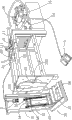
Fig. 1 is a perspective view of the present utility model;
Fig. 2 is the perspective view that amplify the part of Fig. 1;
Fig. 3 is the structure principle chart that the utility model draws the copper pincers.
Embodiment
The utility model is further described with specific embodiment below in conjunction with accompanying drawing, referring to Fig. 1-3:
Draw the copper machine, upper level at frame 10 1 ends is provided with hydraulic cylinder 11, outer end at the piston rod 12 of hydraulic cylinder 11 is hinged with two connecting rods 111, the outer end of two connecting rods 111 is hinged with the scissor pincers handle 201 of copper pincers 20 that draws that can move on frame 10, the other end in frame 10 is provided with elevating mechanism 30, be provided with the location-plate 13 that can block motor stator between elevating mechanism 30 and the frame 10, hydraulic cylinder 11 is by being communicated with oil pump 14, overflow valve 15, electromagnetically operated valve 16 and controlling its action by the control switch of electromagnetically operated valve 16 with oil pipe.
The above-mentioned copper pincers 20 that draw are that to intersect the back at the middle part by two tong arms 205 be that jaw 203, opposite side are pincers handles 201 with the hinged side that forms of jointed shaft, are installed with swing arm 202 on a jaw 203, are provided with flat tooth 204 drawing copper to clamp 20 jaw 203 inboards.
The outer end jointed shaft of above-mentioned piston rod 12 and draw two connecting rods 111 and two sections pincers handles, 201 formation parallel four-bar linkages between the jointed shaft of copper pincers 20.
The above-mentioned copper pincers 20 that draw can be moving on the frame 10: draw on the jointed shaft of copper pincers 20 and be hinged with sliding bar 21, the both sides of sliding bar 21 tower slidably are connected on the slide rail of frame 10 both sides.
Above-mentioned location-plate 13 is: symmetry is hung with location-plate 13 on the other end of frame 10, and the top between two location-plates 13 is provided with the arc opening 131 that can block motor stator, outwards is arranged with pull bar 132 respectively at the middle part in two location-plates, 13 outsides.
Above-mentioned elevating mechanism 30 is: be provided with hydraulic cylinder 33 on an edge-on bar 32 of L type stand 31, the piston rod outer end of hydraulic cylinder 33 upwards is installed with T type slide bar 34, two ends at T type slide bar 34 are respectively equipped with roller 35, on two rollers 35, be hung with driving chain 36, one end of driving chain 36 is fixed in the vertical rod 32 of L type stand 31, the other end is fixed on the lifting platform 37 of L type stand 31, upper surface at lifting platform 37 is interval with two rollers 38, and described hydraulic cylinder 33 is controlled its action by the control switch on the electromagnetically operated valve 16.
Above-mentioned control switch is foot switch 1 or hand switch 2.
Operation principle of the present utility model is: will cut on the lifting platform 37 that the motor stator of cutting that also has copper coil is placed on elevating mechanism 30 with cutting the copper machine, the arc that rises to the location-plate 13 that can block motor stator by hand switch 2 control lifting platforms 37 is opened 131 places, be fixed with the piston rod 12 of the hydraulic cylinder 11 that draws copper pincers 20 to the slip of arc opening 131 places of location-plate 13 by foot switch 1 control again, draw copper pincers 20 to open by parallel four-bar linkage pincers 203 when drawing copper pincers 20 to slide, when drawing copper pincers 20 to draw the swing arm 202 on the copper pincers jaw 203 to allow jaw 203 bite copper coil to the swing of location-plate 13 places, starting foot switch 1 allows the piston rod 12 of the hydraulic cylinder 11 that draws copper pincers 20 move backward, draw copper pincers 20 to allow pincers 203 further sting tight copper coil, separate from motor stator until copper coil by parallel four-bar linkage jaw 203 closures.
The foregoing description only is one of preferred embodiment of the present utility model; be not to limit protection range of the present utility model according to this; so: all equivalences of doing according to structure of the present utility model, shape, principle change, and all should be covered by within the protection range of the present utility model.
Claims (7)
1. draw the copper machine, it is characterized in that: the upper level at frame one end is provided with hydraulic cylinder, outer end at the piston rod of hydraulic cylinder is hinged with two connecting rods, the outer end of two connecting rods is hinged with the scissor pincers handle of copper pincers that draws that can move on frame, the other end in frame is provided with elevating mechanism, be provided with the location-plate that can block motor stator between elevating mechanism and the frame, hydraulic cylinder is by being communicated with oil pump, overflow valve, electromagnetically operated valve and controlling its action by the control switch of electromagnetically operated valve with oil pipe.
2. the copper machine that draws according to claim 1, it is characterized in that: the described copper pincers that draw are that intersecting back at the middle part by two tong arms is that jaw, opposite side are the pincers handles with the hinged side that forms of jointed shaft, on a jaw, be installed with swing arm, be provided with flat tooth in the jaw inboard of drawing the copper pincers.
3. the copper machine that draws according to claim 1 and 2 is characterized in that: two connecting rods between the outer end jointed shaft of described piston rod and the jointed shaft that draws copper pincers clamp petioliforms and become parallel four-bar linkage with two sections.
4. the copper machine that draws according to claim 1 and 2 is characterized in that: the described copper pincers that draw can be mobile on the frame: be hinged with sliding bar on the jointed shaft that draws copper to clamp, the both sides of sliding bar tower slidably are connected on the slide rail of frame both sides.
5. the copper machine that draws according to claim 1, it is characterized in that: described location-plate is: symmetry is hung with location-plate on the other end of frame, top between two location-plates is provided with the arc opening that can block motor stator, outwards is arranged with pull bar respectively at the middle part in the two location-plates outside.
6. the copper machine that draws according to claim 1, it is characterized in that: described elevating mechanism is: be provided with hydraulic cylinder on an edge-on bar of L type stand, the piston rod outer end of hydraulic cylinder upwards is installed with T type slide bar, two ends at T type slide bar are respectively equipped with roller, on two rollers, be hung with driving chain, one end of driving chain is fixed in the vertical rod of L type stand, the other end is fixed on the lifting platform of L type stand, upper surface at lifting platform is interval with two rollers, and described hydraulic cylinder is controlled its action by the control switch on the electromagnetically operated valve.
7. according to claim 1 or the 6 described copper machines that draw, it is characterized in that: described control switch is foot switch or hand switch.
Priority Applications (1)
| Application Number | Priority Date | Filing Date | Title |
|---|---|---|---|
| CN201020101198XU CN201601580U (en) | 2010-01-20 | 2010-01-20 | Copper drawing machine |
Applications Claiming Priority (1)
| Application Number | Priority Date | Filing Date | Title |
|---|---|---|---|
| CN201020101198XU CN201601580U (en) | 2010-01-20 | 2010-01-20 | Copper drawing machine |
Publications (1)
| Publication Number | Publication Date |
|---|---|
| CN201601580U true CN201601580U (en) | 2010-10-06 |
Family
ID=42812640
Family Applications (1)
| Application Number | Title | Priority Date | Filing Date |
|---|---|---|---|
| CN201020101198XU Expired - Fee Related CN201601580U (en) | 2010-01-20 | 2010-01-20 | Copper drawing machine |
Country Status (1)
| Country | Link |
|---|---|
| CN (1) | CN201601580U (en) |
Cited By (5)
| Publication number | Priority date | Publication date | Assignee | Title |
|---|---|---|---|---|
| CN105290357A (en) * | 2015-11-06 | 2016-02-03 | 遵义智鹏高新铝材有限公司 | Lifting and transferring device for aluminum bars |
| CN105290356A (en) * | 2015-11-06 | 2016-02-03 | 遵义智鹏高新铝材有限公司 | Aluminum bar clamping device |
| CN107742957A (en) * | 2017-11-24 | 2018-02-27 | 泗县金皖泵业有限公司 | A kind of stator coil removes device and coil method for dismounting |
| CN110365172A (en) * | 2019-08-12 | 2019-10-22 | 姜近东 | A kind of waste and old motor stator copper wire dismounting equipment |
| CN111037617A (en) * | 2019-11-21 | 2020-04-21 | 龚玉卓 | Insulating adhesive tape cutting device for motor disassembly |
-
2010
- 2010-01-20 CN CN201020101198XU patent/CN201601580U/en not_active Expired - Fee Related
Cited By (7)
| Publication number | Priority date | Publication date | Assignee | Title |
|---|---|---|---|---|
| CN105290357A (en) * | 2015-11-06 | 2016-02-03 | 遵义智鹏高新铝材有限公司 | Lifting and transferring device for aluminum bars |
| CN105290356A (en) * | 2015-11-06 | 2016-02-03 | 遵义智鹏高新铝材有限公司 | Aluminum bar clamping device |
| CN107742957A (en) * | 2017-11-24 | 2018-02-27 | 泗县金皖泵业有限公司 | A kind of stator coil removes device and coil method for dismounting |
| CN110365172A (en) * | 2019-08-12 | 2019-10-22 | 姜近东 | A kind of waste and old motor stator copper wire dismounting equipment |
| CN110365172B (en) * | 2019-08-12 | 2021-05-18 | 赣州市永鑫环保科技有限公司 | Waste motor stator copper wire dismantling equipment |
| CN111037617A (en) * | 2019-11-21 | 2020-04-21 | 龚玉卓 | Insulating adhesive tape cutting device for motor disassembly |
| CN111037617B (en) * | 2019-11-21 | 2021-04-23 | 南京禹智智能科技有限公司 | Insulating adhesive tape cutting device for motor disassembly |
Similar Documents
| Publication | Publication Date | Title |
|---|---|---|
| CN206316401U (en) | A kind of quick perforating device of iron plate for building | |
| CN201601580U (en) | Copper drawing machine | |
| CN203918071U (en) | Steel-plate cutter | |
| CN207464301U (en) | A kind of energy saving aluminium ingot cutter device | |
| CN104070568A (en) | Batten splicing and forming device | |
| CN103009362A (en) | Lifting-type cutter supporting platform | |
| CN204999283U (en) | High -efficient shaped brick piece grabbing device | |
| CN204804364U (en) | Multi -functional automatic brick cutting machine | |
| CN202943616U (en) | Elevation type cutter supporting table | |
| CN203198027U (en) | Board blanking device | |
| CN202480244U (en) | Foam concrete block cutting production line | |
| CN204770891U (en) | Portable steel pipe cutter | |
| CN202657634U (en) | Fully automatic plate placing machine | |
| CN202609489U (en) | Automatic plate loader of building blocks | |
| CN202529567U (en) | Conveying rack for washing machine | |
| CN103658463A (en) | Full-automatic steel bar shearing machine | |
| CN204295894U (en) | A kind of cutting machine of fireproof heat insulating ceramic wafer | |
| CN203998574U (en) | Steel plate separating tool | |
| CN203765062U (en) | Iron sheet shearing device | |
| CN202507319U (en) | Cutting device for molded heat insulation strip | |
| CN2593998Y (en) | Splitting apparatus with sychronous four edges | |
| CN206633061U (en) | Pipe cut-off machines structure | |
| CN201384040Y (en) | Tofu piece squeezer | |
| CN104441267A (en) | Cutting machine for fireproof thermal insulation ceramic plate | |
| CN201546097U (en) | Bi-directional automatic cloth-off |
Legal Events
| Date | Code | Title | Description |
|---|---|---|---|
| C14 | Grant of patent or utility model | ||
| GR01 | Patent grant | ||
| C17 | Cessation of patent right | ||
| CF01 | Termination of patent right due to non-payment of annual fee |
Granted publication date: 20101006 Termination date: 20140120 |