CN201593658U - Lathedog - Google Patents
Lathedog Download PDFInfo
- Publication number
- CN201593658U CN201593658U CN2010201281211U CN201020128121U CN201593658U CN 201593658 U CN201593658 U CN 201593658U CN 2010201281211 U CN2010201281211 U CN 2010201281211U CN 201020128121 U CN201020128121 U CN 201020128121U CN 201593658 U CN201593658 U CN 201593658U
- Authority
- CN
- China
- Prior art keywords
- screw rod
- card
- intermediate plate
- clamping pieces
- hole
- Prior art date
- Legal status (The legal status is an assumption and is not a legal conclusion. Google has not performed a legal analysis and makes no representation as to the accuracy of the status listed.)
- Expired - Fee Related
Links
- 238000009434 installation Methods 0.000 claims description 3
- 230000000903 blocking effect Effects 0.000 claims 1
- 238000000034 method Methods 0.000 abstract description 4
- 235000008331 Pinus X rigitaeda Nutrition 0.000 description 2
- 235000011613 Pinus brutia Nutrition 0.000 description 2
- 241000018646 Pinus brutia Species 0.000 description 2
- 238000010587 phase diagram Methods 0.000 description 1
Images

Landscapes
- Clamps And Clips (AREA)
Abstract
A lathedog adopts the structure that an upper clamp and a lower clamp adopt semicircular structures with connectors arranged at two ends; a longitudinal through hole is formed on the connector at one end of the upper clamp, and a longitudinal concave arc-shaped groove is formed on the connector at the other end thereof; the upper and the lower clamps are in opposite arrangement; through holes are formed at the upper ends of clamping pieces, waist-shaped holes are formed on the walls of the clamping pieces, and screw rods penetrate the through holes of the clamping pieces to be placed in the clamping pieces; pin holes are formed at the lower ends of the screw rods, the two clamping pieces are mounted on the two connectors of the lower clamp respectively, and pins penetrate the pin holes of the lower clamp, the waist-shaped holes of the clamping pieces and the pin holes of the screw rods; and the two clamping pieces and the screw rods are mounted corresponding to the longitudinal through hole and the longitudinal concave arc-shaped groove of the connectors of the upper clamp. In the process of unfolding and folding the lathedog, both the upper and the lower clamps can move up and down along the waist-shaped holes of the clamping pieces, and the lower clamp and the clamping pieces can rotate around the pins. The assembly and disassembly of the lathedog can be achieved so long as nuts of the clamping pieces at two ends are slightly loosened, the end of the upper clamp with the longitudinal concave arc-shaped groove is pulled out of the clamping pieces, and the lathedog is separated through rotating around the pins. The lathedog has the advantages of compact structure and convenient assembly and disassembly.
Description
Technical field
The utility model relates to a kind of pipeline jointing clip.
Background technique
The form that pipeline connects is removed flange-type and is connected, more commonly thimble connector connects, particularly the pipeline in the aviation pneumatic accessories connects, in the prior art, the form that the traditional clip that uses during mesohigh large flow pipe road connects all adopts card up and down to separate fully mounts and dismounts all very inconveniently, especially is easy to card up and down with similar sizes and mixes up and confuse in keeping, just must compare one by one when taking, time-consuming.
Summary of the invention
The purpose of this utility model is to provide a kind of pipeline easy to loading and unloading, that be convenient to whole keeping to connect and uses clip.
The technical solution of the utility model comprises card, blocks down, and last card, following card have the semi-circle structure of connecting head for two ends; On the connecting head of last card one end longitudinal hole is arranged, vertical concave arc groove is arranged on the connecting head of the other end; Last card, following card are oppositely arranged; There is through hole the intermediate plate upper end, on the intermediate plate wall waist shaped hole is arranged, and screw rod penetrates the through hole of intermediate plate and inserts in the intermediate plate; There is pinhole the screw rod lower end, and two intermediate plates are loaded on down two connecting heads of card respectively, and pin-and-hole, the waist shaped hole of intermediate plate and the pinhole of screw rod that pin penetrates down card will play card, intermediate plate and screw rod to be connected as a single entity; Two intermediate plates and screw rod thereof with on link the longitudinal hole of joint, the vertically corresponding installation of concave arc groove.
Said two intermediate plates and screw rod thereof with on link the longitudinal hole of joint, vertically the corresponding installation of concave arc groove specifically is meant: a screw rod passes the longitudinal hole that links joint and is fixed by its nut, and another screw rod passes the vertical concave arc groove that links joint and fixed by its nut.
The connecting head at card two ends has a flange on the utility model.
Intermediate plate and on link the semicircle pad be housed between the joint, the semicircle pad passes screw rod, with on link fitting flange concave circular arc match.
The utility model with intermediate plate, pin up and down card connection be one, opening and closing up in the process of the utility model clip, last card, following card can move up and down along the waist shaped hole on the intermediate plate, following card and intermediate plate can also be that the center rotates with the pin.Only need during mounting or dismounting the nut of two ends intermediate plate is unloaded as pine slightly, an end of last card (end that vertical concave arc groove is arranged) just can be pulled out from intermediate plate, is that the axle rotation is is separately loaded and unloaded clip with the pin.Semicircle pad on last card two end boss helps centering to install.In the process of whole erection, dismounting and keeping all is that the pine of only making part is unloaded, and makes whole work become time saving and energy saving.Compared with prior art, the utility model compact structure, easy to loading and unloading, easily centering is convenient to whole keeping.
Description of drawings
Provide operation instruction that the utility model is described in further detail below in conjunction with accompanying drawing.
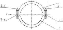
Fig. 1 is a structural representation of the present utility model.
Fig. 2 is that the A of Fig. 1 is to enlarged view.
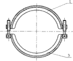
Fig. 3 is the utility model dismounting back phase diagram.
Fig. 4 is the utility model user mode figure.
Embodiment
Among Fig. 1, the utility model will be gone up card 1, block 3 down and link together with intermediate plate 2, pin etc.Last card 1, block 3 down and the semi-circle structure of connecting head is arranged for two ends.On the connecting head of last card 1 one ends longitudinal hole is arranged, vertical concave arc groove is arranged on the connecting head of the other end.Last card 1, block 3 down and be oppositely arranged.Intermediate plate 2-
1(intermediate plate 2-
2) upper end through hole is arranged, on the intermediate plate wall waist shaped hole is arranged.Screw rod 4-
1Penetrate intermediate plate 2-
1Through hole insert intermediate plate 2-
1In; Screw rod 4-
2Penetrate intermediate plate 2-
2Through hole insert intermediate plate 2-
2In.Screw rod 4-
1(screw rod 4-
2) there is pinhole the lower end.Two intermediate plates are loaded on down card 3 two ends connecting heads respectively, and pin penetrates down pin-and-hole, the intermediate plate 2-of card 3
1Waist shaped hole and screw rod 4-
1Pinhole will play card 3, intermediate plate 2-
1With screw rod 4-
1(the connecting head opposite side of card is identical down) is connected as a single entity; The longitudinal hole end of last card 1 connecting head passes screw rod 4-
1, the semicircle pad is passed screw rod 4-
1, on block 1 connecting head vertical concave arc groove end pass screw rod 4-
2, second half ring washer is passed screw rod 4-
2The concave circular arc of card 1 flange is matched with the semicircle pad that passes screw rod, and the other end of two screw rods is connected down itself and intermediate plate on the two ends connecting head of card 3 with pin and pad, then two nuts are screwed in respectively on the outstanding screw rod on plane on the intermediate plate, have just formed the integral body of this clip.
Among Fig. 2, on block 1, intermediate plate 2-
2, following card 3, screw rod 4-
2, nut 5, semicircle pad 6, pin 7.
Among Fig. 3, on block 1, following card 3.
Among Fig. 4, on block 1, following card 3.(having removed nut, pin and intermediate plate)
Claims (4)
1. a clip is characterized in that: go up card, the following semi-circle structure that connecting head is arranged for two ends of blocking; On the connecting head of last card one end longitudinal hole is arranged, vertical concave arc groove is arranged on the connecting head of the other end; Last card, following card are oppositely arranged; There is through hole the intermediate plate upper end, on the intermediate plate wall waist shaped hole is arranged, and screw rod penetrates the through hole of intermediate plate and inserts in the intermediate plate; There is pinhole the screw rod lower end, and two intermediate plates are loaded on down two connecting heads of card respectively, and pin-and-hole, the waist shaped hole of intermediate plate and the pinhole of screw rod that pin penetrates down card will play card, intermediate plate and screw rod to be connected as a single entity; Two intermediate plates and screw rod thereof with on link the longitudinal hole of joint, the vertically corresponding installation of concave arc groove.
2. clip according to claim 1, it is characterized in that: said two intermediate plates and screw rod thereof with on link the longitudinal hole of joint, vertically the concave arc groove is corresponding is installed as: a screw rod passes the longitudinal hole that links joint and is fixed by its nut, and another screw rod passes the vertical concave arc groove that links joint and fixed by its nut.
3. clip according to claim 1 is characterized in that: on block two ends connecting head one flange is arranged.
4. clip according to claim 1 is characterized in that: intermediate plate and on link the semicircle pad be housed between the joint, the semicircle pad passes screw rod, with on link fitting flange concave circular arc match.
Priority Applications (1)
| Application Number | Priority Date | Filing Date | Title |
|---|---|---|---|
| CN2010201281211U CN201593658U (en) | 2010-02-27 | 2010-02-27 | Lathedog |
Applications Claiming Priority (1)
| Application Number | Priority Date | Filing Date | Title |
|---|---|---|---|
| CN2010201281211U CN201593658U (en) | 2010-02-27 | 2010-02-27 | Lathedog |
Publications (1)
| Publication Number | Publication Date |
|---|---|
| CN201593658U true CN201593658U (en) | 2010-09-29 |
Family
ID=42775725
Family Applications (1)
| Application Number | Title | Priority Date | Filing Date |
|---|---|---|---|
| CN2010201281211U Expired - Fee Related CN201593658U (en) | 2010-02-27 | 2010-02-27 | Lathedog |
Country Status (1)
| Country | Link |
|---|---|
| CN (1) | CN201593658U (en) |
Cited By (2)
| Publication number | Priority date | Publication date | Assignee | Title |
|---|---|---|---|---|
| CN107448702A (en) * | 2017-09-29 | 2017-12-08 | 大连长之琳科技发展有限公司 | The cold pipeline of liquid is rigidly connected Quick Release Hoop |
| CN109398901A (en) * | 2018-11-26 | 2019-03-01 | 湖州苕溪文化创意有限公司 | Fixture is used in a kind of packing of writing brush penholder |
-
2010
- 2010-02-27 CN CN2010201281211U patent/CN201593658U/en not_active Expired - Fee Related
Cited By (2)
| Publication number | Priority date | Publication date | Assignee | Title |
|---|---|---|---|---|
| CN107448702A (en) * | 2017-09-29 | 2017-12-08 | 大连长之琳科技发展有限公司 | The cold pipeline of liquid is rigidly connected Quick Release Hoop |
| CN109398901A (en) * | 2018-11-26 | 2019-03-01 | 湖州苕溪文化创意有限公司 | Fixture is used in a kind of packing of writing brush penholder |
Similar Documents
| Publication | Publication Date | Title |
|---|---|---|
| CN201297461Y (en) | Movable joint of pipeline | |
| CN201090859Y (en) | Fast flexible self-locking pipe clamp | |
| CN203394749U (en) | Concrete piston connection device and concrete pump | |
| CN203162351U (en) | Pipe clamp and concrete conveying device provided with same | |
| CN201970261U (en) | Pulling-drawing tool capable of realizing rotational positioning | |
| CN202949195U (en) | Pipeline segment connecting joint of cable protection pipe | |
| CN107907338A (en) | A kind of tailpipe attachment device for engine rig test | |
| CN205714726U (en) | Easy-to-mount drilling pump clip | |
| CN203285795U (en) | Clamp of Christmas tree | |
| CN201493897U (en) | Clamping device of cutting machine | |
| CN209245510U (en) | Vulcanizer pipeline Fast Installation flange apparatus | |
| CN203130705U (en) | Conveniently dismantled and installed casting clamp hoop | |
| CN218947500U (en) | Frock is fixed in throat clamp equipment | |
| CN202417347U (en) | Quick connection clamping tile | |
| CN204175746U (en) | A kind of fast rotational fixed structure | |
| CN203532330U (en) | General tool for centrifugal compressor case pressure testing | |
| CN212929050U (en) | Manual valve convenient to dismantle | |
| CN207893292U (en) | Pipeline swing adapter fixtures for rapid assembly | |
| CN211439807U (en) | Pipe joint assembling and disassembling sleeve suitable for narrow space | |
| CN205928350U (en) | Clamping fixture | |
| CN202031377U (en) | Shed frame rod connecting device | |
| CN201604100U (en) | Accompanying jig for multi-variety engine positioning | |
| CN202228595U (en) | Device for connecting chains of rock drilling machine | |
| CN201243896Y (en) | Hoop body structure of rotary clothes hanger | |
| CN213839164U (en) | End connecting piece of telescopic ejector rod |
Legal Events
| Date | Code | Title | Description |
|---|---|---|---|
| C14 | Grant of patent or utility model | ||
| GR01 | Patent grant | ||
| CF01 | Termination of patent right due to non-payment of annual fee |
Granted publication date: 20100929 Termination date: 20150227 |
|
| EXPY | Termination of patent right or utility model |