CN201569068U - Lightning protection natural energy four-season type hot water system - Google Patents
Lightning protection natural energy four-season type hot water system Download PDFInfo
- Publication number
- CN201569068U CN201569068U CN2009202175950U CN200920217595U CN201569068U CN 201569068 U CN201569068 U CN 201569068U CN 2009202175950 U CN2009202175950 U CN 2009202175950U CN 200920217595 U CN200920217595 U CN 200920217595U CN 201569068 U CN201569068 U CN 201569068U
- Authority
- CN
- China
- Prior art keywords
- energy
- generator
- wind
- solar
- seasons
- Prior art date
- Legal status (The legal status is an assumption and is not a legal conclusion. Google has not performed a legal analysis and makes no representation as to the accuracy of the status listed.)
- Expired - Fee Related
Links
- XLYOFNOQVPJJNP-UHFFFAOYSA-N water Substances O XLYOFNOQVPJJNP-UHFFFAOYSA-N 0.000 title claims abstract description 68
- 238000010438 heat treatment Methods 0.000 claims description 29
- 239000011521 glass Substances 0.000 claims description 9
- 239000000463 material Substances 0.000 claims description 6
- 239000010865 sewage Substances 0.000 claims description 6
- 238000006243 chemical reaction Methods 0.000 claims description 5
- FYYHWMGAXLPEAU-UHFFFAOYSA-N Magnesium Chemical compound [Mg] FYYHWMGAXLPEAU-UHFFFAOYSA-N 0.000 claims description 4
- 238000005286 illumination Methods 0.000 claims description 3
- 238000004321 preservation Methods 0.000 abstract 3
- 239000008236 heating water Substances 0.000 abstract 1
- 238000000034 method Methods 0.000 description 10
- 230000000694 effects Effects 0.000 description 5
- 239000007789 gas Substances 0.000 description 5
- 230000008859 change Effects 0.000 description 4
- 230000009172 bursting Effects 0.000 description 3
- 230000006378 damage Effects 0.000 description 3
- 230000005611 electricity Effects 0.000 description 3
- 238000007710 freezing Methods 0.000 description 3
- 230000008014 freezing Effects 0.000 description 3
- 238000009413 insulation Methods 0.000 description 3
- 238000012423 maintenance Methods 0.000 description 3
- 239000002699 waste material Substances 0.000 description 3
- 238000001816 cooling Methods 0.000 description 2
- 238000010586 diagram Methods 0.000 description 2
- 238000005516 engineering process Methods 0.000 description 2
- 238000009434 installation Methods 0.000 description 2
- 230000000630 rising effect Effects 0.000 description 2
- 230000009466 transformation Effects 0.000 description 2
- 238000010521 absorption reaction Methods 0.000 description 1
- 230000032683 aging Effects 0.000 description 1
- QVGXLLKOCUKJST-UHFFFAOYSA-N atomic oxygen Chemical compound [O] QVGXLLKOCUKJST-UHFFFAOYSA-N 0.000 description 1
- 239000004568 cement Substances 0.000 description 1
- 239000000567 combustion gas Substances 0.000 description 1
- 238000010276 construction Methods 0.000 description 1
- 235000019628 coolness Nutrition 0.000 description 1
- 230000007797 corrosion Effects 0.000 description 1
- 238000005260 corrosion Methods 0.000 description 1
- 230000007547 defect Effects 0.000 description 1
- 230000007123 defense Effects 0.000 description 1
- 230000007812 deficiency Effects 0.000 description 1
- 230000006866 deterioration Effects 0.000 description 1
- 239000004744 fabric Substances 0.000 description 1
- 238000003306 harvesting Methods 0.000 description 1
- 230000008676 import Effects 0.000 description 1
- 230000006872 improvement Effects 0.000 description 1
- JEIPFZHSYJVQDO-UHFFFAOYSA-N iron(III) oxide Inorganic materials O=[Fe]O[Fe]=O JEIPFZHSYJVQDO-UHFFFAOYSA-N 0.000 description 1
- 230000007246 mechanism Effects 0.000 description 1
- 239000001301 oxygen Substances 0.000 description 1
- 229910052760 oxygen Inorganic materials 0.000 description 1
- 230000000505 pernicious effect Effects 0.000 description 1
- 238000001556 precipitation Methods 0.000 description 1
- APTZNLHMIGJTEW-UHFFFAOYSA-N pyraflufen-ethyl Chemical compound C1=C(Cl)C(OCC(=O)OCC)=CC(C=2C(=C(OC(F)F)N(C)N=2)Cl)=C1F APTZNLHMIGJTEW-UHFFFAOYSA-N 0.000 description 1
- 239000003507 refrigerant Substances 0.000 description 1
- 230000008439 repair process Effects 0.000 description 1
- 238000009423 ventilation Methods 0.000 description 1
Images


Classifications
-
- Y—GENERAL TAGGING OF NEW TECHNOLOGICAL DEVELOPMENTS; GENERAL TAGGING OF CROSS-SECTIONAL TECHNOLOGIES SPANNING OVER SEVERAL SECTIONS OF THE IPC; TECHNICAL SUBJECTS COVERED BY FORMER USPC CROSS-REFERENCE ART COLLECTIONS [XRACs] AND DIGESTS
- Y02—TECHNOLOGIES OR APPLICATIONS FOR MITIGATION OR ADAPTATION AGAINST CLIMATE CHANGE
- Y02B—CLIMATE CHANGE MITIGATION TECHNOLOGIES RELATED TO BUILDINGS, e.g. HOUSING, HOUSE APPLIANCES OR RELATED END-USER APPLICATIONS
- Y02B10/00—Integration of renewable energy sources in buildings
- Y02B10/20—Solar thermal
-
- Y—GENERAL TAGGING OF NEW TECHNOLOGICAL DEVELOPMENTS; GENERAL TAGGING OF CROSS-SECTIONAL TECHNOLOGIES SPANNING OVER SEVERAL SECTIONS OF THE IPC; TECHNICAL SUBJECTS COVERED BY FORMER USPC CROSS-REFERENCE ART COLLECTIONS [XRACs] AND DIGESTS
- Y02—TECHNOLOGIES OR APPLICATIONS FOR MITIGATION OR ADAPTATION AGAINST CLIMATE CHANGE
- Y02B—CLIMATE CHANGE MITIGATION TECHNOLOGIES RELATED TO BUILDINGS, e.g. HOUSING, HOUSE APPLIANCES OR RELATED END-USER APPLICATIONS
- Y02B10/00—Integration of renewable energy sources in buildings
- Y02B10/70—Hybrid systems, e.g. uninterruptible or back-up power supplies integrating renewable energies
-
- Y—GENERAL TAGGING OF NEW TECHNOLOGICAL DEVELOPMENTS; GENERAL TAGGING OF CROSS-SECTIONAL TECHNOLOGIES SPANNING OVER SEVERAL SECTIONS OF THE IPC; TECHNICAL SUBJECTS COVERED BY FORMER USPC CROSS-REFERENCE ART COLLECTIONS [XRACs] AND DIGESTS
- Y02—TECHNOLOGIES OR APPLICATIONS FOR MITIGATION OR ADAPTATION AGAINST CLIMATE CHANGE
- Y02E—REDUCTION OF GREENHOUSE GAS [GHG] EMISSIONS, RELATED TO ENERGY GENERATION, TRANSMISSION OR DISTRIBUTION
- Y02E10/00—Energy generation through renewable energy sources
- Y02E10/70—Wind energy
- Y02E10/72—Wind turbines with rotation axis in wind direction
Landscapes
- Wind Motors (AREA)
Abstract
The utility model relates to a lightning protection natural energy four-season type hot water system, which adopts a wind energy and solar energy complementing manner according to characteristics of the climates in most parts of China to collect natural energy. Wind energy and solar energy are converted through an AC generator to electrical energy which can be transmitted and controlled easily, and after being transmitted to a room, the electrical energy is converted to heat energy for heating water. The system comprises a wind generator, a solar generator and a heat preservation water tank, wherein the wind generator is used for converting wind energy to electrical energy and then outputting; the solar generator is used for converting solar energy to electrical energy and then outputting; and the heat preservation water tank comprises an electric heater unit used for converting electrical energy outputted by the wind generator and the solar generator to heat energy so as to heat water inside the heat preservation water tank.
Description
Technical field
The utility model relates to a kind of lighning proof type natural energy four seasons formula hot-water heating system, particularly a kind of can utilize solar energy and wind energy can electrically heated hot water apparatus.
Background technology
Common in the market domestic hot water system mainly contains electric heater, gas heater, solar water heater etc., though there are following shortcoming and defect in actual use in all more convenient practicality.
Common electric heater needs to expend a large amount of electric energy in daily use, has the danger of getting an electric shock and hurting sb.'s feelings when leak current fault occurring, and technical sophistication, needs professional's place under repair when breaking down, and thundery sky also should not use.
Common gas heater needs to expend combustion gas in use, also consumes indoor oxygen simultaneously, need use the ventilation of particularly need windowing when using winter under the environment that ventilates.Can cause indoor temperature to reduce owing to window winter, so the part user is difficult to accomplish correctly use under ventilated environment, when many people use for a long time, may causes indoor anoxic or pernicious gas to be assembled, harm user's personal safety.
Though common solar water heater energy-conserving and environment-protective, northerly winter, the vacuum heat collection pipe in the bursting by freezing solar water heater caused the damage of solar water heater easily when using.Because winter temperature is lower, sunshine deficiency, even in the area, temperate zone, solar water heater has three months at least can not normally be used, and at refrigerant latitudes, the out of use time is then longer.Also be difficult to normal use under the rainy weather continuously in addition.Simultaneously since at present the pipeline of solar water heater be arranged at outdoorly more, cause easily aging, fragile, the easy bursting by freezing of yard piping, and then cause solar water heater normally not use, make that year effective storage life of solar water heater is shorter.Even under normal operating condition, because the water that retains in the yard piping is not effectively heated, need to waste many cold water before causing using, this waste increases progressively with the height increase of floor.Because the vacuum heat collection pipe of common solar water heater and water tank generally are installed in outdoorly, collect heat daytime in addition, can cause the loss of heat to night again though make things convenient for.
Summary of the invention
For solving the problems of the technologies described above, the utility model provides a kind of lighning proof type natural energy four seasons formula hot-water heating system.It adopts the mode of wind energy and solar energy complementation to collect natural energy according to the climatic characteristic in the most of area of China.By alternating current generator wind energy and solar energy are changed into being easy to the electric energy that transmits and control, electric energy is transferred to changes heat energy again into after indoor, water is heated.
Operation principle of the present utility model is as follows: select the vertical pivot wind-driven generator for use, utilize the wind energy of all directions all directions to generate electricity easily and effectively.When utilizing wind energy, also select light power generator for use, sunshine is absorbed by the selectively absorbing layers of vacuum heat-collecting inner tube layer, be converted into heat energy, make the cold air of vacuum heat collection pipe innermost layer be heated, and then the rising of expanding, hot-air outlet by the upper end is derived, form the negative pressure of vacuum heat collection pipe innermost layer, the cold air of outside enters in the admission line via air inlet under the effect of atmospheric pressure, replenishes the air of vacuum heat collection pipe innermost layer, and then be heated, form flowing of cold and hot air.Flow air is the rotation generating of pushing generator impeller on the one hand, also takes away the small amount of thermal energy that generator produces simultaneously, makes the generator cooling, thereby realizes self cooled effect, and the assurance generator is worked under suitable temperature conditions.
Wind-driven generator and light power generator adopt alternating current generator, change wind energy and luminous energy into be easy to transmit electric energy.The alternating current that alternating current generator produces is transferred to attemperater by transfer wire through control cabinet.Heating rod by in the attemperater changes electric energy into heat energy, the water in the attemperater is heated up, and constantly accumulate heat energy.
So only needing that this wind energy and light power generator equipment frame have been located at wind has the light part, for example roof, roof or spacious place, and this system can normally carry out work.
For this reason, the utility model provides a kind of lighning proof type natural energy four seasons formula hot-water heating system, it is characterized in that comprising:
One wind-driven generator is exported after being used for wind energy is converted to electric energy;
One solar generator is exported after being used for solar energy is converted to electric energy;
One attemperater, described attemperater comprises electric heater unit, described electric heater unit is used for the electric energy of described wind-driven generator and the output of described solar generator is converted to heat energy, heats the water in the described attemperater.
In technique scheme, described wind-driven generator employing alternating current generator carries out the conversion between wind energy and the electric energy; Described solar generator employing alternating current generator carries out the conversion between solar energy and the electric energy.
In technique scheme, described wind-driven generator is the vertical pivot wind-driven generator, and described vertical pivot wind-driven generator uses and adds large-scale half-cylindrical blade; Described solar generator uses double end conduction type glass heat-collecting vacuum tube to utilize illumination that medium is heated.
In technique scheme, the described half-cylindrical blade number that described vertical pivot wind-driven generator uses is the 4-6 sheet.
In technique scheme, described medium is an air.
In technique scheme, described wind-driven generator is provided with bucker, and described bucker prevents rainwater and snow-broth inflow generator rotatable parts.
In technique scheme, described double end conduction type glass heat-collecting vacuum tube one end is connected with admission line, and the other end is connected with discharge duct; Air inlet at described admission line is provided with anti-foreign material grid; Water-proof type exhaust watt is set in the gas outlet of described discharge duct.
In technique scheme, described wind-driven generator and described solar generator are installed by the outdoor type generator support, also are provided with balancing weight on described outdoor type generator support.
In technique scheme, the bottom of described attemperater also is provided with cold water outlet, hot water mouth, sewage draining exit, and the top of attemperater is provided with water return outlet, and also being provided with super large in the described attemperater has core magnesium rod.
In technique scheme, described attemperater also includes control box, be provided with thunder-prevention switch and step-down transformer in the described control box, described step-down transformer is a safe voltage below the 36V with the output voltage step-down of described wind-driven generator and described solar generator, uses for described electric heater unit.
The utility model has been obtained following technique effect:
1. adopt the mode of wind energy and solar energy complementation to collect natural energy, almost completely need not pay energy expenditure, operating cost is cheap.And make full use of the climatic characteristic in the most of area of China, promptly most of area sunlight in winter is weak, the sunshine-duration is short but strong wind is many, and summer, sunlight was strong, sunshine-duration is grown but strong wind few (except the southern typhoon zone), wind energy and solar energy complementation, the unit are harvest energy is many, can use all the year round continuously every.
2. adopt vertical pivot to add waterproof bell-type wind-driven generator, can the wind energy of four corners of the world all directions be used, and electric motor mounting structure is simple.By increasing blade area wind energy utilization is improved, increase the bucker design simultaneously, make motor avoid exposing to the sun and rain, can waterproof prevent high temperature, prolong the effective time.
3. double end conduction type vacuum heat collection pipe photoelectric generator, the photoelectric transformation efficiency height can reach about 93%.And heat medium is an air, the danger of no bursting by freezing vacuum heat collection pipe.
4. attemperater is installed in indoorly, and installation and maintenance are convenient, are not subjected to the influence of outdoor day and night difference variation simultaneously, greatly reduce the loss of heat, but also reduced use before the waste of yard piping inner cold water, can accomplish plug and play.As long as normal the use, indoor running water pipe can not freeze, and has avoided the danger of frost crack pipe, aged deterioration.
5. increased thunder-prevention switch, reduced thunderbolt and electric leakage risk, can round-the-clockly use safely.
6. reach more than 10 years (commonly used at present glass heat-collecting vacuum tube service life be 10-15) service life, use cost is low, meets the environment protecting and power-saving requirement.
Description of drawings
Fig. 1 is the wind-driven generator structural representation;
Fig. 2 is wind energy and light power generator combining structure schematic diagram;
Fig. 3 is a double end conduction type glass heat-collecting vacuum tube structural representation;
Fig. 4 is a light power generator structure left view;
Fig. 5 is the light power generator structural front view;
Fig. 6 is electric cisten mechanism schematic diagram for lighning proof type is incubated;
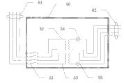
Fig. 7 is an attemperater control box structural representation.
Mark among the figure: 10-wind-driven generator alternating current generator; 11-semicolumn blade (concave surface); 12-semicolumn blade (convex surface); 13-wind-driven generator sharf; 14-wind-driven generator bucker; 15-wind-driven generator mandrel connector; 16-wind-driven generator frame; 20-light power generator alternating current generator; The 21-light power generator; The 22-vacuum heat collection pipe; The 23-admission line; 23-is put the foreign material grid; 25-outdoor type generator support; The 26-balancing weight; 27-waterproof exhaust watt; The 30-attemperater; The 31-condenser hot well liner; The 32-heat-insulation layer; 33-first heating rod; 34-second heating rod; The 35-cold water outlet; The 36-hot water mouth; The 37-sewage draining exit; The 38-water return outlet; 39-has core magnesium rod; The 41-first heating rod terminals; The 42-second heating rod terminals; The 50-control box; The 51-thunder-prevention switch; 52-first step-down transformer; 53-second step-down transformer; 54-first relay indicating light; 55-second relay indicating light; 61-control box input; 62-control box output.
The specific embodiment
Understand and enforcement the utility model for the ease of those of ordinary skills, the utility model is described in further detail below in conjunction with the drawings and the specific embodiments.
As shown in Figure 1, the utility model adopts the vertical axis wind-driven generator, this wind-driven generator comprises wind-driven generator alternating current generator 10, this alternating current generator 10 is connected to wind-driven generator sharf 13 by mandrel connector 15, semicolumn blade 11 by having male and fomale(M﹠F) and 12 rotating drive alternating current generator 10.According to the characteristics of small-sized household wind-power electricity generation, semicolumn blade 11 and 12 areas being strengthened simultaneously, is electric energy with the wind energy transformation of the more any direction of easier absorption, improves the utilization ratio of wind energy.Preferably, the blade of wind-driven generator is the 4-6 sheet.The generator top installs bucker 14 additional more simultaneously, can prevent rainwater, snow-broth inflow generator rotatable parts under the sleety weather situation, avoids load-bearing bearing rust, effectively prolongs the service life of motor.Simultaneously during the broiling summer can shield portions light, avoid generator penetrated by illumination, cause temperature rise too fast.
As shown in Figure 2, the utility model adopts the combining structure of solar energy/light power generator and wind-driven generator.
This light power generator 21 adopts double end conduction type glass heat-collecting vacuum tube 22, and as shown in Figure 3, this vacuum heat collection pipe 22 is the critical component of light power generator, can change solar energy into heat energy.
The structure of light power generator 21 is shown in Fig. 4-5, and this light power generator 21 as medium, drives light power generator with alternating current generator 20 by the air in the heating, vacuum thermal-collecting tube 22 with air.Double end conduction type glass heat-collecting vacuum tube 22 inside are provided with the luminous energy selectively absorbing layers, and the one end is connected with admission line 23, and the other end is connected with discharge duct.The sunshine that is radiated on the vacuum heat collection pipe 22 is absorbed by the selectively absorbing layers of internal layer, be converted into heat energy, make the cold air of vacuum heat collection pipe 22 innermost layers be heated, and then the rising of expanding, hot-air outlet by the upper end is derived, form the negative pressure of vacuum heat collection pipe 22 innermost layers, the cold air of outside is under the effect of atmospheric pressure, enter in the admission line 23 via air inlet, admission line 23 direct cold airs enter in the double end conduction type glass heat-collecting vacuum tube 22 and are heated, and replenish the air of vacuum heat collection pipe 22 innermost layers, and then are heated, form flowing of cold and hot air, produce flow air stream.Flow air promotes the rotation generating of alternating current generator 20 impellers on the one hand, also take away the small amount of thermal energy that alternating current generator 20 produces simultaneously, make alternating current generator 20 coolings, thereby realize self cooled effect, assurance alternating current generator 20 is worked under suitable temperature conditions.Alternating current generator 20 impellers are aimed in the import of admission line 23, make the air push wheel rotation that flows out, and change the kinetic energy of moving air into electric energy by the alternating current generator 20 that is connected with impeller and export.
Air inlet at admission line 23 is provided with anti-foreign material grid 23, is used for stoping airborne foreign material, and for example old polybag, cloth, yarn etc. enter generator, enwind impeller, thereby avoid alternating current generator 20 to quit work.Water-proof type exhaust watts 27 also is set in the gas outlet of discharge duct simultaneously, prevents that the rainwater, snow-broth or other dusts, the foreign material etc. that fall from falling into vacuum heat collection pipe 22 inner chambers, influences thermal conversion efficiency in the air.
Outdoor mounted for convenience of wind energy and light power generator, be provided with outdoor type generator support 25, be used for fixing wind energy and light power generator, on outdoor type generator support 25, also be provided with simultaneously balancing weight 26, be used to strengthen the weight of outdoor type generator support 25, increase the stability of outdoor type generator support 25.This balancing weight 26 can adopt and increase the weight of cement block, and its weight prevents the destruction of bad weathers such as strong wind or heavy rain to wind energy and light power generator much larger than the deadweight of wind energy and light power generator, guarantees the stable operation of wind energy and light power generator.
As shown in Figure 6, for the electric energy with wind energy and light power generator output is converted to required heat energy, the two-way alternating current of wind energy and light power generator output is introduced in the indoor heat insulating water tank 30 by being connected lead respectively.This connects lead and adopts quad or two parallel core leads of two-way to constitute.Middle and lower part in the attemperater 30 is provided with two heating rods, first heating rod 33 and second heating rod 34, link to each other with two-way alternating current respectively with 42 by terminals 41, change the electric energy of input into heat energy, come the water in the heat tracing water tank 30 from wind energy and light power generator.
As shown in Figure 7, attemperater 30 also has a control box 50, and the input 61 of control box 50 links to each other with light power generator with wind energy by connecting lead, is used to introduce the alternating current of wind energy and light power generator output.Alternating current is introduced control box 50 after thunder-prevention switch 51 and step-down transformer 52 link to each other with 53 input port, and the voltage drop of wind energy and light power generator output AC electricity is pressed into safe voltage below the 36V.Step-down transformer 52 is connected with 34 with the heating rod 33 of attemperater respectively with 53 delivery outlet, uses less than the safe voltage of 36V and gives heating rod 33 and 34 power supplies, guarantees user's safety.
When thunderstorm weather, can be by being electrically connected of thunder-prevention switch 51 disconnections and wind energy and light power generator, the inside and outside circuit of disconnection chamber connects, and the trouble free service of assurance system utilizes the hot water that retains in the attemperater 30 to carry out safe shower.Thunder-prevention switch 51 guarantees user's safety with the anti-electric wall of the safety of step-down transformer 52 and 53 construction systems.
Step-down transformer 52 and 53 and the heating rod 33 and 34 of attemperater 30 between be in series with relay indicating light 54 and 55, this indicator lamp 54 and 55 can remind outdoor circuit whether to be in normal operating conditions on the one hand, with convenient maintenance and maintenance, can indicate on the other hand when thunder-prevention switch 51 is in off-state, the indoor and outdoor circuit disconnects, heating rod 33 and 34 in the attemperater 30 does not power on, and is in the safe handling state.
As shown in Figure 6, the bottom of attemperater 30 also is provided with cold water outlet 35, hot water mouth 36, sewage draining exit 37, and the top of attemperater 30 is provided with water return outlet 38.Cold water outlet 35 is inlets of running water, hot water mouth 36 is used for hot water is discharged, the discharge of sewage when sewage draining exit 37 is used in the relatively poor area of water quality attemperater 30 inside are cleaned, water return outlet 38 shows inflow when being used for attemperater 30 water inlets, the prompting user closes water intaking valve when water inlet is expired.
Also being provided with super large in the attemperater 30 has core magnesium rod 39, is used to protect inner bag 31 and heating rod 33 and 34 of attemperater 30, prevents corrosion and precipitation of scales, increases the service life.
Because the utility model is simple in structure, easy for installation, characteristics such as energy-conserving and environment-protective, be suitable for the interior non-typhoon region of global range and install and use, be specially adapted to general resident, barber shop, small-sized restaurant, hostel (the low floor peace of limit room user), army sentry post, frontier defense website etc. and locate as bath hot water and north of china in winter heating of house.
Above embodiment only is a kind of embodiment of the present utility model, and it describes comparatively concrete and detailed, but can not therefore be interpreted as the restriction to the utility model claim.Its concrete structure and size can be adjusted according to actual needs accordingly.Should be pointed out that for the person of ordinary skill of the art under the prerequisite that does not break away from the utility model design, can also make some distortion and improvement, these all belong to protection domain of the present utility model.
Claims (10)
1. lighning proof type natural energy four seasons formula hot-water heating system is characterized in that comprising:
One wind-driven generator is exported after being used for wind energy is converted to electric energy;
One solar generator is exported after being used for solar energy is converted to electric energy;
One attemperater (30), described attemperater comprise electric heater unit (33,34), and described electric heater unit is used for the electric energy of described wind-driven generator and the output of described solar generator is converted to heat energy, heats the water in the described attemperater (30).
2. lighning proof type natural energy four seasons formula hot-water heating system according to claim 1 is characterized in that: described wind-driven generator employing alternating current generator carries out the conversion between wind energy and the electric energy; Described solar generator employing alternating current generator carries out the conversion between solar energy and the electric energy.
3. lighning proof type natural energy four seasons formula hot-water heating system according to claim 1, it is characterized in that: described wind-driven generator is the vertical pivot wind-driven generator, described vertical pivot wind-driven generator uses and adds large-scale half-cylindrical blade; Described solar generator uses double end conduction type glass heat-collecting vacuum tube (22) to utilize illumination that medium is heated.
4. lighning proof type natural energy four seasons formula hot-water heating system according to claim 3 is characterized in that: the described half-cylindrical blade number that described vertical pivot wind-driven generator uses is the 4-6 sheet.
5. lighning proof type natural energy four seasons formula hot-water heating system according to claim 3, it is characterized in that: described medium is an air.
6. lighning proof type natural energy four seasons formula hot-water heating system according to claim 5, it is characterized in that: described wind-driven generator is provided with bucker (14), and described bucker (14) prevents rainwater and snow-broth inflow generator rotatable parts.
7. lighning proof type natural energy four seasons formula hot-water heating system according to claim 6 is characterized in that: described double end conduction type glass heat-collecting vacuum tube (22) one ends are connected with admission line (23), and the other end is connected with discharge duct; Air inlet at described admission line (23) is provided with anti-foreign material grid (24); Be provided with water-proof type exhaust watt (27) in the gas outlet of described discharge duct.
8. lighning proof type natural energy four seasons formula hot-water heating system according to claim 7, it is characterized in that: described wind-driven generator and described solar generator are installed by outdoor type generator support (25), also are provided with balancing weight (26) on described outdoor type generator support (25).
9. lighning proof type natural energy four seasons formula hot-water heating system according to claim 8, it is characterized in that: the bottom of described attemperater (30) also is provided with cold water outlet (35), hot water mouth (36), sewage draining exit (37), the top of attemperater (30) is provided with water return outlet (38), and also being provided with super large in the described attemperater (30) has core magnesium rod (39).
10. lighning proof type natural energy four seasons formula hot-water heating system according to claim 9, it is characterized in that: described attemperater (30) also includes control box (50), be provided with thunder-prevention switch (51) and step-down transformer (52 in the described control box (50), 53), described step-down transformer (52,53) with the output voltage step-down of described wind-driven generator and described solar generator be safe voltage below the 36V, use for described electric heater unit (33,34).
Priority Applications (1)
| Application Number | Priority Date | Filing Date | Title |
|---|---|---|---|
| CN2009202175950U CN201569068U (en) | 2009-09-28 | 2009-09-28 | Lightning protection natural energy four-season type hot water system |
Applications Claiming Priority (1)
| Application Number | Priority Date | Filing Date | Title |
|---|---|---|---|
| CN2009202175950U CN201569068U (en) | 2009-09-28 | 2009-09-28 | Lightning protection natural energy four-season type hot water system |
Publications (1)
| Publication Number | Publication Date |
|---|---|
| CN201569068U true CN201569068U (en) | 2010-09-01 |
Family
ID=42661358
Family Applications (1)
| Application Number | Title | Priority Date | Filing Date |
|---|---|---|---|
| CN2009202175950U Expired - Fee Related CN201569068U (en) | 2009-09-28 | 2009-09-28 | Lightning protection natural energy four-season type hot water system |
Country Status (1)
| Country | Link |
|---|---|
| CN (1) | CN201569068U (en) |
Cited By (2)
| Publication number | Priority date | Publication date | Assignee | Title |
|---|---|---|---|---|
| CN102345331A (en) * | 2011-07-13 | 2012-02-08 | 葛加君 | Construction method of solar energy lightning protection facility on building roof |
| CN105444407A (en) * | 2015-12-28 | 2016-03-30 | 罗建华 | Water-storage electric water heater safe to use |
-
2009
- 2009-09-28 CN CN2009202175950U patent/CN201569068U/en not_active Expired - Fee Related
Cited By (3)
| Publication number | Priority date | Publication date | Assignee | Title |
|---|---|---|---|---|
| CN102345331A (en) * | 2011-07-13 | 2012-02-08 | 葛加君 | Construction method of solar energy lightning protection facility on building roof |
| CN105444407A (en) * | 2015-12-28 | 2016-03-30 | 罗建华 | Water-storage electric water heater safe to use |
| CN105444407B (en) * | 2015-12-28 | 2018-05-11 | 中山市海迪威电器有限公司 | Water storage type electric water heater safe to use |
Similar Documents
| Publication | Publication Date | Title |
|---|---|---|
| CN201875878U (en) | Solar photoelectric mutual-compensation electric water heater | |
| KR101015804B1 (en) | Cogeneration System Linking Combined Alternative Energy Generation with Solar and Wind Power | |
| CN102913978B (en) | Renewable energy source and building integrated comprehensive utilization system | |
| CN204043216U (en) | Photovoltaic and photothermal solar and air can combine hot-water heating system | |
| CN103727772A (en) | Heat pump drying and heating system powered by solar energy and wind energy in complementary mode | |
| CN109066415A (en) | A kind of aeration radiation system of buried photovoltaic substation | |
| CN201368554Y (en) | Natural energy source air-conditioning system | |
| CN103825533A (en) | Power supplying and cooling device for communication device | |
| CN103334883A (en) | Wind power generation curtain wall | |
| CN105507613B (en) | A kind of energy-conserving and environment-protective board house | |
| CN202578028U (en) | Solar house | |
| CN205227483U (en) | Solar heating device | |
| CN203687175U (en) | Solar energy and wind power comprehensive utilization water supply and air-conditioning energy saving system for high-rise buildings | |
| CN205878678U (en) | Solar and wind energy air can heating refrigeration and hot -water heating system | |
| CN212405448U (en) | Energy-saving house building for realizing temperature regulation by utilizing underground facilities | |
| CN204616798U (en) | Solar energy tortoise survives the winter culturing pool | |
| CN112483322A (en) | Gravity wind power generation device | |
| CN203298412U (en) | Solar energy-saving air conditioning system | |
| CN202235040U (en) | Solar and wind power shower | |
| CN207585108U (en) | A kind of frost-cracking-preventing solar water heater based on wind energy and solar panel | |
| CN108240551A (en) | Utilize the LNG air-heating type gasifiers of photovoltaic/photothermal integration system | |
| CN103485983A (en) | Intelligent distribution combined type energy system of building | |
| CN102635159A (en) | Solar house | |
| CN200999701Y (en) | Renewable sources utilizing equipment integrating wind power, waterpower and solar | |
| CN208123883U (en) | Utilize photovoltaic/photothermal integration system LNG air-heating type gasifier |
Legal Events
| Date | Code | Title | Description |
|---|---|---|---|
| C14 | Grant of patent or utility model | ||
| GR01 | Patent grant | ||
| C17 | Cessation of patent right | ||
| CF01 | Termination of patent right due to non-payment of annual fee |
Granted publication date: 20100901 Termination date: 20130928 |