CN201529814U - A fully automatic gear hobbing machine - Google Patents
A fully automatic gear hobbing machine Download PDFInfo
- Publication number
- CN201529814U CN201529814U CN2009202002400U CN200920200240U CN201529814U CN 201529814 U CN201529814 U CN 201529814U CN 2009202002400 U CN2009202002400 U CN 2009202002400U CN 200920200240 U CN200920200240 U CN 200920200240U CN 201529814 U CN201529814 U CN 201529814U
- Authority
- CN
- China
- Prior art keywords
- gear hobbing
- pneumatic
- machine
- feeding
- workpiece
- Prior art date
- Legal status (The legal status is an assumption and is not a legal conclusion. Google has not performed a legal analysis and makes no representation as to the accuracy of the status listed.)
- Expired - Fee Related
Links
- 230000005540 biological transmission Effects 0.000 claims abstract description 9
- 239000000463 material Substances 0.000 claims description 2
- RYGMFSIKBFXOCR-UHFFFAOYSA-N Copper Chemical compound [Cu] RYGMFSIKBFXOCR-UHFFFAOYSA-N 0.000 abstract description 4
- 229910052802 copper Inorganic materials 0.000 abstract description 4
- 239000010949 copper Substances 0.000 abstract description 4
- 230000001360 synchronised effect Effects 0.000 description 4
- 238000005516 engineering process Methods 0.000 description 3
- 238000000034 method Methods 0.000 description 1
Images


Classifications
-
- Y—GENERAL TAGGING OF NEW TECHNOLOGICAL DEVELOPMENTS; GENERAL TAGGING OF CROSS-SECTIONAL TECHNOLOGIES SPANNING OVER SEVERAL SECTIONS OF THE IPC; TECHNICAL SUBJECTS COVERED BY FORMER USPC CROSS-REFERENCE ART COLLECTIONS [XRACs] AND DIGESTS
- Y02—TECHNOLOGIES OR APPLICATIONS FOR MITIGATION OR ADAPTATION AGAINST CLIMATE CHANGE
- Y02P—CLIMATE CHANGE MITIGATION TECHNOLOGIES IN THE PRODUCTION OR PROCESSING OF GOODS
- Y02P70/00—Climate change mitigation technologies in the production process for final industrial or consumer products
- Y02P70/10—Greenhouse gas [GHG] capture, material saving, heat recovery or other energy efficient measures, e.g. motor control, characterised by manufacturing processes, e.g. for rolling metal or metal working
Landscapes
- Gear Processing (AREA)
Abstract
本实用新型公开了一种全自动滚齿机,具有自动上料器,其特征在于:所述全自动滚齿机包括气动送料机构、气动夹紧机构、工件机、气动脱料机构、滚齿机构、液压升降机构和传动机构,滚齿机构与液压升降机构连接,工件机和滚齿机构与传动机构传动连接,所述自动上料器出口与气动送料机构之间设有输送工件的滑道。本实用新型主要用于“乐器类、铜蜗轮工件”的全自动滚齿,使用方便,操作简单、生产效率高、减轻劳动强度、滚齿稳定、产品定位准确可靠、确保产品质量。
The utility model discloses a fully automatic gear hobbing machine, which has an automatic feeder, and is characterized in that: the fully automatic gear hobbing machine includes a pneumatic feeding mechanism, a pneumatic clamping mechanism, a workpiece machine, a pneumatic stripping mechanism, a gear hobbing mechanism, and a hydraulic lifting mechanism And the transmission mechanism, the gear hobbing mechanism is connected with the hydraulic lifting mechanism, the workpiece machine and the gear hobbing mechanism are connected with the transmission mechanism, and a slideway for conveying workpieces is provided between the outlet of the automatic feeder and the pneumatic feeding mechanism. The utility model is mainly used for fully automatic gear hobbing of "musical instruments and copper worm gear workpieces". It is convenient to use, simple to operate, high in production efficiency, reduces labor intensity, stable in gear hobbing, accurate and reliable in product positioning, and ensures product quality.
Description
【技术领域】【Technical field】
本实用新型涉及一种滚齿机,特别涉及的是一种用于“乐器类、铜蜗轮工件”全自动滚齿的滚齿机。The utility model relates to a gear hobbing machine, in particular to a gear hobbing machine for automatic gear hobbing of "musical instruments and copper worm wheel workpieces".
【背景技术】【Background technique】
现有技术加工“乐器类、铜蜗轮工件”一般是将“蜗轮毛胚”放到滚齿机上一个个进行滚齿,操作繁琐、生产效率低、劳动强度高、滚齿定位不准确、不能确保产品质量。The processing of "musical instruments and copper worm gear workpieces" in the existing technology is generally to put the "worm gear blanks" on the gear hobbing machine one by one for gear hobbing. quality.
【发明内容】【Content of invention】
鉴于目前公知技术存在的问题,本实用新型要解决的技术问题是在于提供一种能够对“乐器类、铜蜗轮工件”进行全自动滚齿的专用滚齿机。In view of the problems existing in the known technology at present, the technical problem to be solved by the utility model is to provide a special gear hobbing machine capable of fully automatic gear hobbing of "musical instruments and copper worm gear workpieces".
为解决上述技术问题,本实用新型是采取如下技术方案来完成的:In order to solve the problems of the technologies described above, the utility model is accomplished by taking the following technical solutions:
一种全自动滚齿机,具有自动上料器,其特征在于:所述全自动滚齿机包括气动送料机构、气动夹紧机构、工件机、气动脱料机构、滚齿机构、液压升降机构和传动机构,滚齿机构与液压升降机构连接,工件机和滚齿机构与传动机构传动连接,所述自动上料器出口与气动送料机构之间设有输送工件的滑道。所述气动送料机构包括送料气缸、送料架和气缸座,送料架与气缸活塞杆连接,送料架的前端设有由拉簧控制的夹持器。A fully automatic gear hobbing machine with an automatic feeder, characterized in that: the fully automatic gear hobbing machine includes a pneumatic feeding mechanism, a pneumatic clamping mechanism, a workpiece machine, a pneumatic stripping mechanism, a gear hobbing mechanism, a hydraulic lifting mechanism and a transmission mechanism, the gear hobbing machine The mechanism is connected with the hydraulic lifting mechanism, the workpiece machine and the hobbing mechanism are connected with the transmission mechanism, and a slideway for conveying workpieces is provided between the outlet of the automatic feeder and the pneumatic feeding mechanism. The pneumatic feeding mechanism includes a feeding cylinder, a feeding frame and a cylinder seat, the feeding frame is connected with the piston rod of the cylinder, and the front end of the feeding frame is provided with a gripper controlled by an extension spring.
本实用新型加工时只需将“蜗轮毛胚”放到自动上料器的振动盘内,通过调节振动器的振幅大小来控制送料的速度,通过滑道把工件送至气动送料机构,此时气动送料机构再把工件夹持送到指定位置,由气动夹紧机构把工件顶到工件机处作夹紧状态,工件机带动工件转动,这时滚齿机构在液压升降机构的控制下移动到工作区间停留进行滚齿工作,然后返回原处,此时蜗轮加工完毕,气动夹紧机构返回,随后气动脱料机构动作,把加工好留在工件机上的蜗轮拔掉后复位,这样机器不断重复上述动作,蜗轮一个个被加工好,从而实现蜗轮滚齿的全自动化。所以说,本实用新型具有使用方便,操作简单、生产效率高、减轻劳动强度、滚齿稳定、产品定位准确可靠、确保产品质量的特点。When the utility model is processed, it is only necessary to put the "worm wheel blank" into the vibrating plate of the automatic feeder, control the feeding speed by adjusting the amplitude of the vibrator, and send the workpiece to the pneumatic feeding mechanism through the slideway. At this time The pneumatic feeding mechanism then clamps the workpiece to the designated position, and the pneumatic clamping mechanism pushes the workpiece to the workpiece machine for clamping state, and the workpiece machine drives the workpiece to rotate. At this time, the hobbing mechanism moves to the working position under the control of the hydraulic lifting mechanism. Stop in the interval for gear hobbing work, and then return to the original position. At this time, the worm gear is processed, the pneumatic clamping mechanism returns, and then the pneumatic stripping mechanism operates to pull out the worm gear that has been processed and left on the workpiece machine and reset it, so that the machine repeats the above Action, the worm gears are processed one by one, so as to realize the full automation of worm gear hobbing. Therefore, the utility model has the characteristics of convenient use, simple operation, high production efficiency, reduced labor intensity, stable gear hobbing, accurate and reliable product positioning, and guaranteed product quality.
【附图说明】【Description of drawings】
本实用新型有如下附图:The utility model has following drawings:
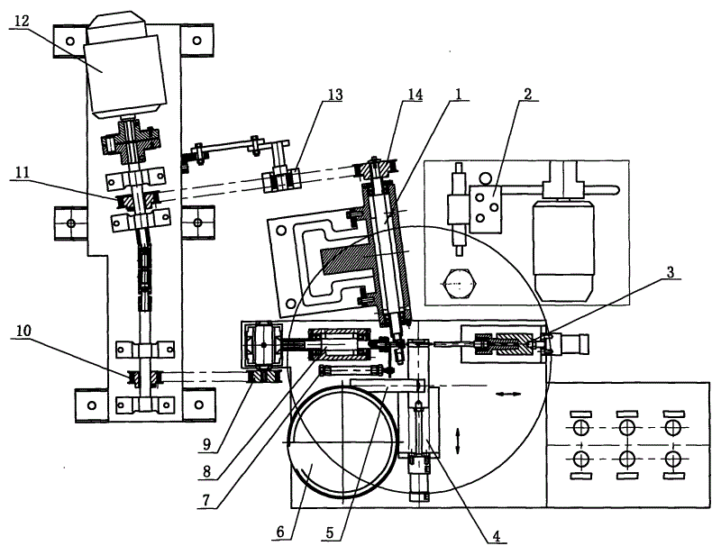
图1为本实用新型的结构示意图Fig. 1 is the structural representation of the utility model
图2为图1的局部放大图Figure 2 is a partial enlarged view of Figure 1
图3为图1中气动送料机构的左视图放大Figure 3 is an enlarged left view of the pneumatic feeding mechanism in Figure 1
【具体实施方式】【Detailed ways】
如图所示,该全自动滚齿机包括自动上料器6、气动送料机构4、气动夹紧机构3、工件机8、气动脱料机构7、滚齿机构1、液压升降机构2和传动机构;所述自动上料器6内设有振动盘,通过调节振动器的振幅大小可以控制送料的速度(自动上料器为现有技术),自动上料器出口与气动送料机构4之间设有输送工件34的滑道5;所述气动送料机构4包括送料气缸30、送料架28和气缸座29,送料架28与送料气缸30活塞杆连接,送料架28的前端设有由拉簧32控制的夹持器33,夹持器33铰接在送料架28的前端,拉簧32一端连接在夹持器33上,另一端通过弹簧座31与送料架28连接,夹持器和送料架前端一起将工件34夹持;所述气动夹紧机构3包括夹紧气缸27、顶尖座25和气缸座26,顶尖座25与夹紧气缸27活塞杆连接,顶尖座25上通过顶尖套24连接右顶尖23;所述工件机8包括机座18和主轴17,主轴和机座之间通过轴承连接,主轴17的右端轴头连接左顶尖19,左端轴头传动连接同步带轮9;所述气动脱料机构7包括脱料气缸15和连接在脱料气缸活塞杆上的脱料杆16,脱料杆16设在所述左顶尖19的外圆侧边;所述滚齿机构1与液压升降机构2连接,滚齿机构1具有的滚齿头包括滚齿刀轴21和机架20,刀轴和机架之间通过轴承连接,刀轴21的前端轴头连接滚齿刀22,后端轴头连接同步带轮14,滚齿头在液压升降机构2的控制下可上下移动;所述传动机构包括电机12,电机12的输出端连接有同步带轮10、11,同步带轮10、11与同步带轮9、14分别通过同步带连接,同步带轮11和同步带轮14之间设有张紧轮13。As shown in the figure, the fully automatic gear hobbing machine includes an
本实用新型是这样工作的,首先将“蜗轮毛胚”放到自动上料器6的振动盘内,通过调节振动器的振幅大小来控制送料的速度,通过滑道5把工件34送至气动送料机构4送料架28的上方A位置,由夹持器33夹持,送料气缸30动作再把工件夹持送到指定B位置,此时夹紧气缸27动作,右顶尖23将工件顶到工件机8的左顶尖C位置处并作夹紧状态,工件机的主轴17以1.5r/s的速度带动工件顺时针旋转,待滚齿,此时送料气缸30回程夹持工件,同时滚齿头的刀轴21以24r/s的转速,在液压系统控制下缓缓而下移动到工作区间停留进行滚齿工作,然后返回原处,此时蜗轮加工完毕,夹紧气缸27返回,随后脱料气缸15动作,脱料杆16把加工好留在工件机左顶尖19上的蜗轮拔掉,蜗轮一个个落入工件框,然后脱料气缸15复位,这样机器不断重复上述动作,蜗轮一个个被加工好,从而实现蜗轮滚齿的全自动化。The utility model works like this. First, put the "worm wheel blank" into the vibrating plate of the
Claims (2)
Priority Applications (1)
| Application Number | Priority Date | Filing Date | Title |
|---|---|---|---|
| CN2009202002400U CN201529814U (en) | 2009-11-06 | 2009-11-06 | A fully automatic gear hobbing machine |
Applications Claiming Priority (1)
| Application Number | Priority Date | Filing Date | Title |
|---|---|---|---|
| CN2009202002400U CN201529814U (en) | 2009-11-06 | 2009-11-06 | A fully automatic gear hobbing machine |
Publications (1)
| Publication Number | Publication Date |
|---|---|
| CN201529814U true CN201529814U (en) | 2010-07-21 |
Family
ID=42525224
Family Applications (1)
| Application Number | Title | Priority Date | Filing Date |
|---|---|---|---|
| CN2009202002400U Expired - Fee Related CN201529814U (en) | 2009-11-06 | 2009-11-06 | A fully automatic gear hobbing machine |
Country Status (1)
| Country | Link |
|---|---|
| CN (1) | CN201529814U (en) |
Cited By (5)
| Publication number | Priority date | Publication date | Assignee | Title |
|---|---|---|---|---|
| CN102328136A (en) * | 2011-01-23 | 2012-01-25 | 林瑞荣 | Automatic processing mechanism of worm gear hobbing |
| CN103240465A (en) * | 2013-05-09 | 2013-08-14 | 王刚 | Gear ejecting machine for making gears |
| CN103753339A (en) * | 2014-01-03 | 2014-04-30 | 宁波科立华建材科技有限公司 | Automatic feeding-discharging mechanism for horizontal gear hobbing machines |
| CN104343900A (en) * | 2014-10-29 | 2015-02-11 | 佛山科学技术学院 | Transmission mechanism of gear hobbing machine |
| CN108296574A (en) * | 2018-04-04 | 2018-07-20 | 广东金力变速科技股份有限公司 | A kind of automatic charging gear-hobbing machine |
-
2009
- 2009-11-06 CN CN2009202002400U patent/CN201529814U/en not_active Expired - Fee Related
Cited By (8)
| Publication number | Priority date | Publication date | Assignee | Title |
|---|---|---|---|---|
| CN102328136A (en) * | 2011-01-23 | 2012-01-25 | 林瑞荣 | Automatic processing mechanism of worm gear hobbing |
| CN102328136B (en) * | 2011-01-23 | 2013-04-10 | 林瑞荣 | Automatic processing mechanism of worm gear hobbing |
| CN103240465A (en) * | 2013-05-09 | 2013-08-14 | 王刚 | Gear ejecting machine for making gears |
| CN103240465B (en) * | 2013-05-09 | 2015-08-19 | 王刚 | A kind of apical tooth machine for making gear |
| CN103753339A (en) * | 2014-01-03 | 2014-04-30 | 宁波科立华建材科技有限公司 | Automatic feeding-discharging mechanism for horizontal gear hobbing machines |
| CN103753339B (en) * | 2014-01-03 | 2016-03-30 | 宁波科立华建材科技有限公司 | Horizontal hobbing machine automatic feeding and discharging mechanism |
| CN104343900A (en) * | 2014-10-29 | 2015-02-11 | 佛山科学技术学院 | Transmission mechanism of gear hobbing machine |
| CN108296574A (en) * | 2018-04-04 | 2018-07-20 | 广东金力变速科技股份有限公司 | A kind of automatic charging gear-hobbing machine |
Similar Documents
| Publication | Publication Date | Title |
|---|---|---|
| CN201168732Y (en) | Integrated pipe bender | |
| CN101474651B (en) | Integrated pipe bender | |
| CN110102698B (en) | Forging production line | |
| CN104016126B (en) | Cylinder circular disc class workpiece feeding mechanical hand | |
| CN209140470U (en) | A kind of pipe chamfering machine handling equipment | |
| CN203621979U (en) | Automatic clamping device for shaft workpieces | |
| CN208788593U (en) | A kind of rotatable manipulator | |
| CN201529721U (en) | Full-automatic hole pressing machine | |
| CN201304491Y (en) | Dedicated vehicle eccentric machine | |
| CN201168823Y (en) | Multifunctional metal pipe cutting device | |
| CN103861963A (en) | Automatic thin wall gold tube necking machine | |
| CN201082471Y (en) | Full-automatic inner chamfering machine | |
| CN205266918U (en) | Garlic cuts navel machine | |
| CN204736057U (en) | Vertical combination grinding machine | |
| CN101590542B (en) | Fully automatic bolt chamfering machine | |
| CN203887263U (en) | Drilling machine for brake pad | |
| CN203265451U (en) | Stamping machine automatic feeding device | |
| CN201889345U (en) | Press type binding device | |
| CN104589134B (en) | A kind of small hollow pipe fitting both-end processing machine | |
| CN113680941A (en) | A two-way hammer forging press | |
| CN203787740U (en) | Wire feeding and stripping device for cable | |
| CN204819807U (en) | Automatic drive material machine | |
| CN205575918U (en) | Bottle -making machine automatic clamp stub bar device | |
| CN205437371U (en) | Multifunctional pipe end forming machine | |
| CN203538240U (en) | Full automatic intelligent noodle cutter |
Legal Events
| Date | Code | Title | Description |
|---|---|---|---|
| C14 | Grant of patent or utility model | ||
| GR01 | Patent grant | ||
| C17 | Cessation of patent right | ||
| CF01 | Termination of patent right due to non-payment of annual fee |
Granted publication date: 20100721 Termination date: 20101106 |