CN201521180U - Install adjustable door stops - Google Patents
Install adjustable door stops Download PDFInfo
- Publication number
- CN201521180U CN201521180U CN2009202114139U CN200920211413U CN201521180U CN 201521180 U CN201521180 U CN 201521180U CN 2009202114139 U CN2009202114139 U CN 2009202114139U CN 200920211413 U CN200920211413 U CN 200920211413U CN 201521180 U CN201521180 U CN 201521180U
- Authority
- CN
- China
- Prior art keywords
- door stopper
- thread
- door
- chassis
- suction
- Prior art date
- Legal status (The legal status is an assumption and is not a legal conclusion. Google has not performed a legal analysis and makes no representation as to the accuracy of the status listed.)
- Expired - Fee Related
Links
Images


Landscapes
- Securing Of Glass Panes Or The Like (AREA)
Abstract
本实用新型涉及一种安装可调节门吸,包括门吸底盘,套环,门吸顶部球体,吸铁石,吸头槽,吸头槽固定部分,弹簧。门吸顶部球体下面的颈部下端设有下连接螺纹,门吸底盘上部连接座上设有上连接螺纹,门吸顶部球体与门吸底盘通过下连接螺纹和上连接螺纹旋合连接。本实用新型降低了之前墙壁组件颈部很容易断裂的风险,连接部分采用密螺纹连接,使两部分的连接更加紧密,且在断裂情况下容易更换;通过细微的旋转调节来保证墙壁组件的磁体头部与门板组件吸合面达到最大化,与底部扩展的螺孔槽双重保证了吸合面的最大化,且使得安装和更换更简便易行,省料,省时,省力。
The utility model relates to an adjustable door stopper, which comprises a door stopper chassis, a collar, a top sphere of the door stopper, an iron magnet, a suction head groove, a fixing part of the suction head groove, and a spring. The lower end of the neck below the top sphere of the door stopper is provided with a lower connection thread, and the upper connection seat of the door stopper chassis is provided with an upper connection thread, and the top sphere of the door stopper and the door stopper chassis are screwed together by the lower connection thread and the upper connection thread. The utility model reduces the risk that the neck of the previous wall component is easily broken, and the connecting part adopts a dense thread connection, which makes the connection of the two parts tighter, and is easy to replace in the case of breakage; the magnet of the wall component is guaranteed by fine rotation adjustment The suction surface between the head and the door panel assembly is maximized, and the extended screw hole groove with the bottom double ensures the maximum suction surface, and makes installation and replacement easier, saving materials, time and effort.
Description
技术领域technical field
本实用新型涉及一种新的门吸,特别是一种安装时可调节门吸。The utility model relates to a new door stopper, in particular to a door stopper which can be adjusted during installation.
背景技术Background technique
现在市场上销售的门吸,都是地吸或壁吸,且门吸的样式单调,所用种类、材料不多,这就使得市场上的各种门吸的竞争力下降,没有太突出的优点。门吸一般都是有地面(或墙壁)组件和门板组件组成,有些门吸仅仅是通过修改样式:如由原来的立柱式修改为圆盘式,其基本的原理并没有改变,都是有墙壁(或地)组件中的磁体部分(吸铁石)、支撑部分和门板组件中的与磁体相互吸引的材料组成。与吸铁石相连的门吸颈部位置由于受所用材料的限制,目前仅限于合金、铝、或铜材料制成,这样,很容易就会出现一个问题,当用力不当将门推向墙壁组件(或地面)或安装角度不准确时,很容易使墙壁(或地面)组件中的磁体头颈部与安装固定部位之间断裂,这就需要重新更换新的墙壁组件。随之而来的问题是,新更换的门吸墙壁组件的螺孔并不一定正好合适当初在地面或墙壁所凿的螺孔,这样,有三种可以解决的方案,如:一、依所更换的新门吸墙壁组件与门板组件正好对整为基础,按照新门吸墙壁组件上的螺孔位置,重新在墙面或地面上钻孔,这样很容易使原本整洁的房间地面或墙壁出现因钻孔位置差别很小、钻孔位置很难控制而出现碎裂或破损,使新门吸无法使用,破坏了门板、地面和墙壁的完整性和美观性;二、重新筛选合适的门吸,这样可能需要耗费很多的时间和精力去一一核对是否与原门吸的墙面或地面螺孔位置对齐,还要考虑墙壁(或地面)组件中的磁体头部与门板组件有完全的结合面,否则门吸的作用会大打折扣;三、在保证不破坏原来地面或者墙面的完整性和美观性的基础上,需要通过精准的测量,将地面或者墙面上的孔位置正标于所换门吸墙壁组件上,然后重新找钻孔机械在重新更换的门吸上钻孔,钻到新换墙壁组件上螺孔的位置正好符合原来墙面或地面螺孔的位置,这也是需要耗费较多的时间和精力,虽然能保证墙面、地面和门板的完整性。The door stoppers currently on the market are all floor suction or wall stoppers, and the style of the door stoppers is monotonous, and the types and materials used are not many, which makes the competitiveness of various door stoppers on the market decline, and there are no outstanding advantages. . Door stoppers are generally composed of ground (or wall) components and door panel components. Some door stoppers are only modified by modifying the style: if the original column type is changed to a disc type, the basic principle has not changed, and there are walls. The (or ground) magnet part (magnet) in the assembly, the support part and the material in the door panel assembly that attract each other with the magnet. Due to the limitation of the material used, the position of the neck of the door suction connected to the magnet is currently limited to alloy, aluminum, or copper materials. In this way, a problem will easily occur. When the door is pushed to the wall assembly (or the ground) with improper force ) or the installation angle is inaccurate, it is easy to break between the head and neck of the magnet in the wall (or ground) assembly and the fixed part of the installation, which requires replacement of a new wall assembly. The ensuing problem is that the screw holes of the newly replaced door stopper wall assembly are not necessarily just right for the screw holes that were originally drilled on the ground or wall. In this way, there are three solutions that can be solved, such as: 1. Based on the alignment of the new door stopper wall assembly and the door panel assembly, according to the position of the screw holes on the new door stopper wall assembly, re-drill holes on the wall or the ground, so that it is easy to make the original clean room floor or wall appear defective The difference in the drilling position is very small, and the drilling position is difficult to control, resulting in chipping or damage, which makes the new door stopper unusable, and destroys the integrity and aesthetics of the door panel, floor and wall; 2. Re-select the appropriate door stopper, It may take a lot of time and effort to check whether it is aligned with the wall or ground screw holes of the original door stopper, and also consider that the magnet head in the wall (or ground) component has a complete joint surface with the door panel component. , otherwise the function of the door stopper will be greatly reduced; 3. On the basis of ensuring that the integrity and aesthetics of the original floor or wall are not damaged, it is necessary to accurately measure the position of the hole on the floor or wall to the desired location. Replace the door stopper on the wall assembly, and then find a drilling machine to drill holes on the replaced door stopper until the position of the screw hole on the newly replaced wall assembly is just in line with the position of the original wall or ground screw hole. More time and energy, although it can ensure the integrity of walls, floors and door panels.
发明内容Contents of the invention
本实用新型是要提供一种安装可调节门吸,该门吸安装和更换更简便易行,省料,省时,省力,并且能保证吸合面的最大化。The utility model is to provide an adjustable door stopper, which is easier to install and replace, saves material, time and labor, and can ensure the maximum of the suction surface.
为实现上述目的,本实用新型的技术方案是:一种安装可调节门吸,包括门吸底盘,套环,门吸顶部球体,吸铁石,吸头槽,吸头槽固定部分,弹簧,其特点是:门吸顶部球体下面的颈部下端设有下连接螺纹,门吸底盘上部连接座上设有上连接螺纹,门吸顶部球体与门吸底盘通过下连接螺纹和上连接螺纹旋合连接。In order to achieve the above purpose, the technical solution of the utility model is: an adjustable door stopper, including a door stopper chassis, a collar, a door stopper top ball, a magnet, a suction head slot, a suction head slot fixing part, a spring, and its characteristics Yes: the lower end of the neck under the top sphere of the door stopper is provided with a lower connection thread, and the upper connection seat of the door stopper chassis is provided with an upper connection thread, and the top sphere of the door stopper and the door stopper chassis are screwed and connected by the lower connection thread and the upper connection thread.
门吸底盘下面开有三个扩展螺孔槽,且三个扩展螺孔槽呈均布设置。下连接螺纹和上连接螺纹为细牙螺纹。There are three expansion screw hole slots under the door suction chassis, and the three expansion screw hole slots are evenly distributed. The lower connecting thread and the upper connecting thread are fine thread.
本实用新型的有益效果是:The beneficial effects of the utility model are:
1、降低了之前墙壁组件颈部很容易断裂的风险,连接部分采用密螺纹连接,使两部分的连接更加紧密,且在断裂情况下容易更换;1. It reduces the risk that the neck of the previous wall component is easily broken. The connection part is connected by a tight thread, which makes the connection between the two parts tighter and easy to replace in case of breakage;
2、墙壁(或地面)组件部分采用密螺纹连接,即使在底部螺孔安装之后,仍有可能出现磁体头部与门板部件之间连接不紧密、吸合面较小的情况,但是密螺纹可以在保证上下两部分连接紧密的同时,也可以通过细微的旋转调节来保证墙壁组件的磁体头部与门板组件吸合面达到最大化,与底部扩展的螺孔槽双重保证了吸合面的最大化,且使得安装和更换更简便易行,省料,省时,省力。2. The wall (or ground) components are connected by dense threads. Even after the bottom screw holes are installed, there may still be cases where the connection between the magnet head and the door panel parts is not tight and the suction surface is small, but the dense threads can While ensuring the tight connection of the upper and lower parts, the magnet head of the wall assembly and the door panel assembly can be maximized through fine rotation adjustments, and the screw hole groove extended with the bottom double ensures the maximum attraction surface It makes installation and replacement easier, saves material, time and effort.
附图说明Description of drawings
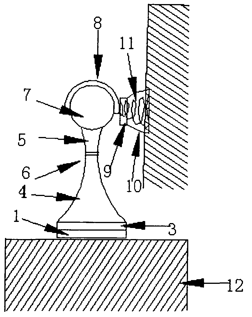
图1是本实用新型的结构安装示意图,其中(a)是地面安装示意图,(b)是墙壁安装示意图;Fig. 1 is the structural installation schematic diagram of the present utility model, and wherein (a) is the ground installation schematic diagram, (b) is the wall installation schematic diagram;
图2是本实用新型的结构分解示意图;Fig. 2 is a schematic diagram of structural decomposition of the utility model;
图3是门吸底部扩展螺孔槽示意图;Figure 3 is a schematic diagram of the extended screw hole slot at the bottom of the door stopper;
图4是门吸底部扩展螺孔槽内螺丝的安装位置平面示意图;Figure 4 is a schematic plan view of the installation position of the screw in the expanded screw hole slot at the bottom of the door stopper;
图5是门吸底部扩展螺孔槽内螺丝的安装位置立体示意图;Fig. 5 is a three-dimensional schematic diagram of the installation position of the screw in the extended screw hole slot at the bottom of the door stopper;
图6是吸槽头示意图。Figure 6 is a schematic diagram of the suction groove head.
具体实施方式Detailed ways
以下结合附图和具体实施例对本实用新型做进一步说明Below in conjunction with accompanying drawing and specific embodiment the utility model is described further
如图1至图6所示,本实用新型的安装可调门吸,包括门吸底盘1,套环3,门吸顶部球体7,吸铁石8,吸头槽9,吸头槽固定部分10,弹簧11等。As shown in Figures 1 to 6, the installation adjustable door stopper of the present utility model includes a
门吸顶部球体7下面的颈部下端设有下连接螺纹5,门吸底盘1上部连接座4上设有上连接螺纹6,门吸顶部球体7与门吸底盘2通过下连接螺纹5和上连接螺纹6旋合连接。The lower end of the neck below the door suction
门吸底盘1下面开有三个扩展螺孔槽13,且三个扩展螺孔槽13呈均布设置。下连接螺纹5和上连接螺纹6为细牙螺纹。There are three expansion
在图1、图2中,首先在地面12或者墙壁14上按照图3、图4中底盘1上扩展孔槽13的位置在墙壁14或者地面12上凿上位置合适的固定螺丝孔,图2中固定螺丝2采用带有密螺纹的螺丝,可以加固底盘1的固定,对于固定好的底盘1,依次安装固定螺丝2,套环3,门吸颈部以上部分包括门吸顶部球体7,吸铁石8作为整体,可以与作为整体的门吸底盘1,连接座4部分通过密螺纹相连,下连接螺纹5和上连接螺纹6是细牙密制螺纹,这样做的目的是保证在门吸颈部以下部分安装固定好以后,可以通过细微的调节,保证吸铁石8与图1中吸头槽9有尽量大的吸合面,充分发挥门吸的作用,本实用新型的突出点也正是体现在以图3至图5中的扩展螺孔槽和以图2中的下连接螺纹5和上连接螺纹6处的细牙螺纹为特色,下连接螺纹5和上连接螺纹6处在没有螺纹的情况下很容易因为用力不当或其它原因导致下连接螺纹5和上连接螺纹6处断裂,此实用新型既保证了安装作业时简便易行,准确可靠,又可使门吸在下连接螺纹5和上连接螺纹6处断裂时更换更加简便、易行,且能保证吸铁石8与图1中吸头槽9的最大吸合面。在图3至图5中,门吸底盘1处的固定螺丝孔由原来的孔变为扩展螺孔槽13,这样在安装时可根据需要旋转底盘1,既方便在安装时的凿孔作业,也方便安装。在安装好以上地面12或墙壁14组件后,便可根据图6中吸槽头底部固定螺孔的位置依次安装吸头槽固定部分10,弹簧11,吸头槽9。此外,图6中所示的弹簧11还可以有效的降低由吸铁石8与吸头槽9在吸合时发出的声响,起到缓冲作用。如此安装后,再适当调整地面(或墙壁)组件中与吸铁石相连的螺纹的位置,使位置达到最佳化。In Fig. 1 and Fig. 2, first on the
本实用新型与现有门吸相比,在结构和安装上有较大的区别,具体体现在以下两方面:一、在墙壁(或地面)组件中,与墙面(或地面)接触的墙壁组件部分,原来是只有三个螺孔,本文将三个螺孔扩展为三个单独的扩展螺孔槽,螺孔槽凹限的部分可使固定用的螺丝与门吸底盘紧密固定,如图4所示与原来单独的螺孔相比,本门吸的墙壁部分因螺孔槽位置扩展,即使因为墙壁(或地面)组件部分坏掉,也不会再去像前述方法一样,只需轻轻的转动墙壁(或地面)组件的底座部分,对准地面或者墙面螺孔位置即可,大大节约了如上述方法三所用的时间和精力,并且使安装的准确度有了很大程度的改进和提升,保证了墙面和地面的完整性和美观性。二、在墙壁组件部分,将磁体头部以下2-3cm处改用细牙螺纹连接,如图1、2、3所示,使整个墙壁组件部分一分为二,这样的优点在于:1、降低了之前墙壁组件颈部很容易断裂的风险,连接部分采用密螺纹连接,使两部分的连接更加紧密,且在断裂情况下容易更换;2、墙壁(或地面)组件部分采用密螺纹连接,即使在底部螺孔安装之后,仍有可能出现磁体头部与门板部件之间连接不紧密、吸合面较小的情况,但是密螺纹可以在保证上下两部分连接紧密的同时,也可以通过细微的旋转调节来保证墙壁组件的磁体头部与门板组件吸合面达到最大化,与底部扩展的螺孔槽双重保证了吸合面的最大化,且使得安装和更换更简便易行,省料,省时,省力。本门吸为所有现存门吸的更换提出了一个更佳的解决方案。Compared with the existing door stopper, the utility model has a big difference in structure and installation, which is embodied in the following two aspects: 1. In the wall (or ground) assembly, the wall contacting the wall (or ground) The component part originally had only three screw holes. In this paper, the three screw holes are expanded into three separate extended screw hole slots. The concave part of the screw hole slot can make the fixing screws tightly fixed with the door suction chassis, as shown in the figure As shown in 4, compared with the original single screw hole, the wall part of the door stopper is expanded due to the position of the screw hole slot. Gently turn the base part of the wall (or ground) assembly to align with the ground or wall screw holes, which greatly saves the time and energy used in the third method above, and greatly improves the accuracy of the installation. Improvements and enhancements ensure the integrity and aesthetics of walls and floors. 2. In the part of the wall assembly, replace the 2-3cm below the head of the magnet with a fine thread connection, as shown in Figures 1, 2, and 3, so that the entire wall assembly is divided into two. The advantages of this are: 1. It reduces the risk that the neck of the previous wall component is easily broken. The connection part is connected by a dense thread, which makes the connection of the two parts tighter and easy to replace in case of breakage; 2. The wall (or ground) component part is connected by a dense thread, Even after the bottom screw holes are installed, it is still possible that the connection between the magnet head and the door panel parts is not tight and the suction surface is small. Rotational adjustment to ensure that the magnet head of the wall assembly and the door panel assembly maximize the suction surface, and the expanded screw hole groove at the bottom double ensures the maximum suction surface, and makes installation and replacement easier and easier, saving materials ,save time and energy. This door stop provides a better solution for the replacement of all existing door stoppers.
Claims (3)
Priority Applications (1)
| Application Number | Priority Date | Filing Date | Title |
|---|---|---|---|
| CN2009202114139U CN201521180U (en) | 2009-10-28 | 2009-10-28 | Install adjustable door stops |
Applications Claiming Priority (1)
| Application Number | Priority Date | Filing Date | Title |
|---|---|---|---|
| CN2009202114139U CN201521180U (en) | 2009-10-28 | 2009-10-28 | Install adjustable door stops |
Publications (1)
| Publication Number | Publication Date |
|---|---|
| CN201521180U true CN201521180U (en) | 2010-07-07 |
Family
ID=42507356
Family Applications (1)
| Application Number | Title | Priority Date | Filing Date |
|---|---|---|---|
| CN2009202114139U Expired - Fee Related CN201521180U (en) | 2009-10-28 | 2009-10-28 | Install adjustable door stops |
Country Status (1)
| Country | Link |
|---|---|
| CN (1) | CN201521180U (en) |
Cited By (3)
| Publication number | Priority date | Publication date | Assignee | Title |
|---|---|---|---|---|
| CN102128429A (en) * | 2011-01-24 | 2011-07-20 | 陶国胜 | Azimuth angle adjustable mounting ring of square ceiling lamp |
| CN105332576A (en) * | 2015-12-11 | 2016-02-17 | 徐敏旺 | Door stop |
| US9745785B2 (en) | 2013-08-06 | 2017-08-29 | Gregory Header | Door catch |
-
2009
- 2009-10-28 CN CN2009202114139U patent/CN201521180U/en not_active Expired - Fee Related
Cited By (3)
| Publication number | Priority date | Publication date | Assignee | Title |
|---|---|---|---|---|
| CN102128429A (en) * | 2011-01-24 | 2011-07-20 | 陶国胜 | Azimuth angle adjustable mounting ring of square ceiling lamp |
| US9745785B2 (en) | 2013-08-06 | 2017-08-29 | Gregory Header | Door catch |
| CN105332576A (en) * | 2015-12-11 | 2016-02-17 | 徐敏旺 | Door stop |
Similar Documents
| Publication | Publication Date | Title |
|---|---|---|
| CN110260050B (en) | A support device for integrated stove exhaust pipe and its installation method | |
| CN201221257Y (en) | Adjustable lower hinge device of refrigerator | |
| CN208918980U (en) | A furniture panel connector | |
| CN202452920U (en) | Mounting hole detection device for seat slider of saloon car | |
| CN208777615U (en) | A kind of stone dry hanging system | |
| CN211573066U (en) | Hanger rail mounting structure | |
| CN114439178A (en) | Assembly type leveling assembly and leveling keel capable of being installed quickly | |
| CN111851911A (en) | An reinforced external pendant for laying medium and large wall tiles and its application | |
| CN207183113U (en) | A kind of switch socket magazine obturator | |
| CN203477608U (en) | Fixing pipe clamp used for pipeline | |
| CN213062764U (en) | Screw type supporting device | |
| CN207598007U (en) | A kind of easy-to-mount handle mounting structure | |
| CN214498077U (en) | Woodwork character beam | |
| CN209526191U (en) | A Dielectric Resonant Rod Support Structure | |
| CN203500203U (en) | Adjusting device of board layer positioning pin | |
| CN208438324U (en) | A kind of glass automated production magazine | |
| CN221743005U (en) | A self-tapping screw anti-deviation structure | |
| CN208113120U (en) | Traffic signals cabinet | |
| CN201089984Y (en) | Panel level adjustment for high bays | |
| CN220622424U (en) | Quick positioning countersunk head screw | |
| CN205842855U (en) | Air-conditioning indoor hanging unit | |
| CN204819249U (en) | Gearbox PB parking ware moment of torsion detects supplementary anchor clamps | |
| CN109779188B (en) | Leveling screw assembly for assembly | |
| CN216552833U (en) | Wall facing brick mounting structure | |
| CN219099811U (en) | Bridge template with bearing structure |
Legal Events
| Date | Code | Title | Description |
|---|---|---|---|
| C14 | Grant of patent or utility model | ||
| GR01 | Patent grant | ||
| C17 | Cessation of patent right | ||
| CF01 | Termination of patent right due to non-payment of annual fee |
Granted publication date: 20100707 Termination date: 20101028 |