CN201449297U - Simple high-precision energy metering device - Google Patents
Simple high-precision energy metering device Download PDFInfo
- Publication number
- CN201449297U CN201449297U CN2008201708455U CN200820170845U CN201449297U CN 201449297 U CN201449297 U CN 201449297U CN 2008201708455 U CN2008201708455 U CN 2008201708455U CN 200820170845 U CN200820170845 U CN 200820170845U CN 201449297 U CN201449297 U CN 201449297U
- Authority
- CN
- China
- Prior art keywords
- metering device
- energy metering
- loop configuration
- simple high
- flow
- Prior art date
- Legal status (The legal status is an assumption and is not a legal conclusion. Google has not performed a legal analysis and makes no representation as to the accuracy of the status listed.)
- Expired - Lifetime
Links
- XLYOFNOQVPJJNP-UHFFFAOYSA-N water Substances O XLYOFNOQVPJJNP-UHFFFAOYSA-N 0.000 claims abstract description 22
- 238000009530 blood pressure measurement Methods 0.000 claims description 14
- 239000008400 supply water Substances 0.000 claims description 2
- 238000005259 measurement Methods 0.000 abstract description 9
- 238000012423 maintenance Methods 0.000 abstract description 4
- 238000004378 air conditioning Methods 0.000 abstract description 2
- 230000002457 bidirectional effect Effects 0.000 abstract 1
- 239000012530 fluid Substances 0.000 description 9
- 238000007789 sealing Methods 0.000 description 6
- 238000009434 installation Methods 0.000 description 4
- 238000005265 energy consumption Methods 0.000 description 3
- 230000007547 defect Effects 0.000 description 2
- 238000010586 diagram Methods 0.000 description 2
- 238000010438 heat treatment Methods 0.000 description 2
- 238000000034 method Methods 0.000 description 2
- 239000002699 waste material Substances 0.000 description 2
- 230000009286 beneficial effect Effects 0.000 description 1
- 238000006243 chemical reaction Methods 0.000 description 1
- 238000004134 energy conservation Methods 0.000 description 1
- 238000005516 engineering process Methods 0.000 description 1
Images


Classifications
-
- Y—GENERAL TAGGING OF NEW TECHNOLOGICAL DEVELOPMENTS; GENERAL TAGGING OF CROSS-SECTIONAL TECHNOLOGIES SPANNING OVER SEVERAL SECTIONS OF THE IPC; TECHNICAL SUBJECTS COVERED BY FORMER USPC CROSS-REFERENCE ART COLLECTIONS [XRACs] AND DIGESTS
- Y02—TECHNOLOGIES OR APPLICATIONS FOR MITIGATION OR ADAPTATION AGAINST CLIMATE CHANGE
- Y02A—TECHNOLOGIES FOR ADAPTATION TO CLIMATE CHANGE
- Y02A20/00—Water conservation; Efficient water supply; Efficient water use
Landscapes
- Measuring Volume Flow (AREA)
Abstract
本实用新型涉及一种计量装置,旨在提供应用于中央空调管道能量和流量测量的简易高精度能量计量装置。该装置包括流量筒、压强传感器A和压强传感器B,压强传感器A和压强传感器B通过电缆与流量计量表连接;流量筒的内部装有一个多孔流量板,流量筒的两端各安装有一个平均压强测量部件,平均压强测量部件通过导压孔分别与压强传感器A和压强传感器B连通;供水温度传感器和回水温度传感器分别安装于供水管道和回水管道上,并分别通过电缆与能量计量表相连接。本实用新型具有测量精度高、结构简单,维护方便。多孔流量板为可更换式部件,维护十分方便、性能可靠、价格低廉,具备双向能量计量功能等特点。
The utility model relates to a metering device, which aims to provide a simple and high-precision energy metering device used in central air-conditioning pipeline energy and flow measurement. The device includes a flow tube, a pressure sensor A and a pressure sensor B, and the pressure sensor A and the pressure sensor B are connected to the flow meter through a cable; a porous flow plate is installed inside the flow tube, and an average flow plate is installed at both ends of the flow tube. The pressure measuring part and the average pressure measuring part are respectively connected to the pressure sensor A and the pressure sensor B through the pressure guide hole; the water supply temperature sensor and the return water temperature sensor are respectively installed on the water supply pipe and the return water pipe, and are connected to the energy meter through the cable respectively. connected. The utility model has the advantages of high measuring precision, simple structure and convenient maintenance. The porous flow plate is a replaceable part, which is very convenient for maintenance, reliable in performance, low in price, and has the characteristics of bidirectional energy metering function and so on.
Description
技术领域technical field
本实用新型涉及一种计量装置,特别涉及一种应用于中央空调管道能量和流量测量的简易高精度能量计量装置。The utility model relates to a metering device, in particular to a simple and high-precision energy metering device used in central air-conditioning pipeline energy and flow measurement.
背景技术Background technique
目前我国在能耗指标上远远低于世界先进水平,普遍存在能耗高、浪费严重等现象。如何贯彻执行节能减排技术已日益引起人们的重视,尤其在我国北方,采暖能耗是同类气候条件下发达国建的3-5倍,由于在用户使用过程中普遍缺少有效的计量装置,在北方取暖收费普遍采用按房间面积计算,导致用户节能意识淡薄,能量浪费严重,同时违背了公平与公正的原则,用与不用一样、用多用少一样,能量计量装置的普及亟待提上日程。目前能量计量装置也开始在我国部分区域逐步采用,以提高能源利用率。但是目前能量计量装置普遍存在以下问题,绝大部分能量计量装置为进口产品,价格昂贵,同时由于口径问题不能普及到户;其次其精度对工程实际安装条件比较苛刻,在实际工程使用中存在诸多缺陷。At present, my country's energy consumption indicators are far below the world's advanced level, and there are widespread phenomena such as high energy consumption and serious waste. How to implement energy-saving and emission-reduction technologies has increasingly attracted people's attention, especially in northern my country, where heating energy consumption is 3-5 times that of developed countries under the same climatic conditions. Heating charges in the north are generally calculated according to the room area, which leads to weak awareness of energy conservation among users and serious energy waste. At the same time, it violates the principle of fairness and justice. At present, energy metering devices have also begun to be gradually adopted in some areas of our country to improve energy utilization. However, the following problems generally exist in energy metering devices at present. Most of the energy metering devices are imported products, which are expensive, and cannot be popularized to households due to the problem of caliber; secondly, their accuracy is relatively harsh on the actual installation conditions of the project. defect.
目前公知的还没有简易的高精度能量计量装置,具有结构简单,性能可靠,价格便宜等优势。At present, there is no simple and high-precision energy metering device known, which has the advantages of simple structure, reliable performance, and low price.
实用新型内容Utility model content
本实用新型主要是为了克服现有能量计量过程中存在的缺陷,提供一种应用于管道管道能量计量的简易高精度能量计量装置。The main purpose of the utility model is to overcome the defects existing in the existing energy measurement process, and to provide a simple and high-precision energy measurement device applied to pipeline energy measurement.
为了解决上述技术问题,本实用新型是通过以下技术方案实现的。In order to solve the above technical problems, the utility model is realized through the following technical solutions.
本实用新型提供了一种简易高精度能量计量装置,包括流量筒、压强传感器A和压强传感器B,压强传感器A和压强传感器B通过电缆与流量计量表连接;流量筒的内部装有一个多孔流量板,流量筒的两端各安装有一个平均压强测量部件,平均压强测量部件通过导压孔分别与压强传感器A和压强传感器B连通;供水温度传感器和回水温度传感器分别安装于供水管道和回水管道上,并分别通过电缆与能量计量表相连接;The utility model provides a simple and high-precision energy metering device, which includes a flow tube, a pressure sensor A and a pressure sensor B. The pressure sensor A and the pressure sensor B are connected to the flow meter through a cable; a porous flow meter is installed inside the flow tube. An average pressure measuring part is installed at both ends of the flow cylinder, and the average pressure measuring part is respectively connected with the pressure sensor A and the pressure sensor B through the pressure guide hole; the water supply temperature sensor and the return water temperature sensor are respectively installed in the water supply pipe and the return water On the water pipeline, and respectively connected with the energy meter through the cable;
所述平均压强测量部件为环形结构,其环壁上设置若干引压孔;环形结构至少有一个侧面延伸突出于环形结构的外表面,与环形结构的外表面构成环形槽。The average pressure measuring part is a ring structure, and several pressure introduction holes are arranged on the ring wall; at least one side of the ring structure protrudes from the outer surface of the ring structure, forming an annular groove with the outer surface of the ring structure.
作为一种改进,所述平均压强测量部件点环形结构的两个侧面均延伸突出于环形外表面,与环形外表面构成环形槽。As an improvement, both side surfaces of the point ring structure of the average pressure measuring component extend and protrude from the outer ring surface, forming an annular groove with the outer ring surface.
作为一种改进,所述平均压强测量部件的环形结构延伸突出的侧面,其端面上设置用于连接的螺纹。As an improvement, the annular structure of the average pressure measuring component has an extended protruding side surface, and threads for connection are provided on the end surface.
作为一种改进,所述平均压强测量部件的环形结构延伸突出的侧面上设置安装孔。As an improvement, installation holes are provided on the protruding side of the annular structure of the average pressure measuring component.
作为一种改进,所述平均压强测量部件的侧面设置安装孔,其环形结构的壁上均匀布置若干引压孔。As an improvement, mounting holes are provided on the side of the average pressure measuring component, and several pressure introduction holes are evenly arranged on the wall of the ring structure.
作为一种改进,所述多孔流量板上设置导流孔,其边缘有一环状的凹槽,密封圈安装于凹槽中.As an improvement, a guide hole is set on the porous flow plate, and there is an annular groove on the edge, and the sealing ring is installed in the groove.
作为一种改进,所述的多孔流量板上的导流孔呈中心对称的方式均匀布置。As an improvement, the guide holes on the porous flow plate are evenly arranged in a center-symmetric manner.
与现有技术相比,本实用新型的有益效果是:Compared with the prior art, the beneficial effects of the utility model are:
1、测量精度高。由于采用多孔流量板作为节流装置,多孔流量板可根据不同情况作相应的调整以更加符合实际测量情况,多孔流量板具有整流的作用,使流场更加平稳增加压差测量的稳定性,同时采用平均压强测量部件和采用平均压强测量部件提高压差测量准确性以提高能量测量的精度;1. High measurement accuracy. Since the porous flow plate is used as the throttling device, the porous flow plate can be adjusted according to different situations to be more in line with the actual measurement situation. The porous flow plate has the function of rectification, making the flow field more stable and increasing the stability of differential pressure measurement. Adopting the average pressure measuring part and adopting the average pressure measuring part to improve the accuracy of differential pressure measurement to improve the accuracy of energy measurement;
2、结构简单,维护方便。多孔流量板为可更换式部件,维护十分方便;2. Simple structure and easy maintenance. The porous flow plate is a replaceable part, which is very convenient for maintenance;
3、性能可靠,价格低廉。简易高精度能量计量装置的主要计量部件均为简单的机械结构,具有结构简单、性能可靠、价格低廉等优势;3. Reliable performance and low price. The main metering components of the simple high-precision energy metering device are all simple mechanical structures, which have the advantages of simple structure, reliable performance, and low price;
4、双向能量计量功能。由于本实用新型具有结构对称性,因此安装时无需考虑流向,减少安装失误。4. Two-way energy metering function. Since the utility model has structural symmetry, there is no need to consider the flow direction during installation, reducing installation errors.
附图说明Description of drawings
图1是本实用新型流量计的主视图;Fig. 1 is the front view of the utility model flow meter;
图2是本实用新型流量计的俯视图(为便于观察,将流量计量表绘制在一侧);Fig. 2 is the top view of the utility model flow meter (for the convenience of observation, the flow meter is drawn on one side);
图3是本实用新型流量计的左视图;Fig. 3 is the left side view of the utility model flow meter;
图4是图3中A-A向的剖面图;Fig. 4 is the sectional view of A-A direction in Fig. 3;
图5是平均压差测量部件的结构示意图;Fig. 5 is a structural schematic diagram of an average differential pressure measuring component;
图6是图5中B-B向的剖面图;Fig. 6 is the sectional view of B-B direction in Fig. 5;
图7是多孔流量板的结构示意图;Fig. 7 is a structural schematic diagram of a porous flow plate;
图8是图7中C-C向的剖面图。Fig. 8 is a sectional view taken along direction C-C in Fig. 7 .
具体实施方式Detailed ways
参考附图4,下面将对本实用新型进行详细描述:With reference to accompanying drawing 4, the utility model will be described in detail below:
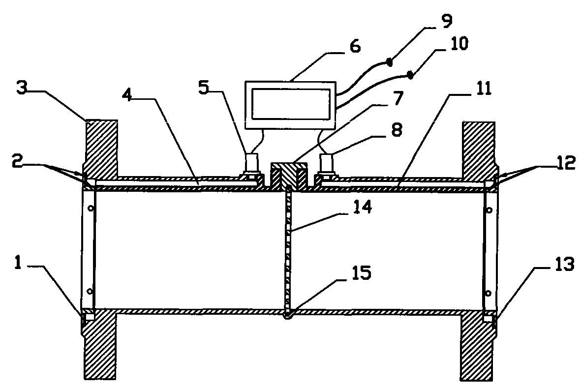
具体实施例4提供了一种简易高精度能量计量装置,包括平均压强测量部件1、密封垫2、包括流量筒3、导压孔4、压强传感器A5、能量计量表6、流量计盖7、压强传感器B8、供水温度传感器9、回水温度传感器10、导压孔11、密封垫12、平均压强测量部件13、多孔流量板14、密封圈15;平均压强测量部件1和平均压强测量部件13以固定螺钉穿过安装孔101安装于流量筒3的两端;密封垫2和密封垫12分别安装于流量筒3和平均压强测量部件1、平均压强测量部件13之间;导压孔4与平均压强测量部件1相连通;导压孔11与平均压强测量部件13相连通;压强传感器A5安装于导压孔4上,与导压孔4相连通;压强传感器B8安装于导压孔11上,与导压孔11相连通;压强传感器A5和压强传感器B8通过电缆与能量计量表6相连接;供水温度传感器9和回水温度传感器10通过电缆与能量计量表6相连接;多孔流量板14上槽142内安装有密封圈15,安装于流量筒3内;流量计盖7安装于流量筒3上,将多孔流量板14安装于流量筒3内。Embodiment 4 provides a simple and high-precision energy metering device, including an average pressure measuring component 1, a
根据附图4,具体工作原理和步骤如下所述:According to accompanying drawing 4, specific working principle and steps are as follows:
(1)将简易高精度能量计量装置安装于测量管道中;(1) Install a simple high-precision energy metering device in the measuring pipeline;
(2)在正常工作时,流体流经流量筒3,在流体流入流量筒3时,流体通过平均压强测量部件1的引压孔102进入导压孔4,能量计量表6通过压强传感器A5测量获得压强值P1。由于密封垫2安装于流量筒3和平均压差测量部件1之间,流体只能通过引压孔102进入导压孔4;(2) During normal operation, the fluid flows through the
(3)流体流经多孔流量板14时,产生压差,由于密封圈15安装于多孔流量12板上,使流体只能通过多孔流量板14中的导流孔141进行流通;(3) When the fluid flows through the
(4)同样在流体流出流量筒3时,流体通过平均压强测量部件13的引压孔102进入导压孔11,能量计量表6通过压强传感器B8测量获得压强值P2,由于密封垫12安装于流量筒3和平均压差测量部件13之间,流体只能通过引压孔102进入导压孔11;(4) When the fluid flows out of the
(5)能量计量表6通过公式获得压差值ΔP=P1-P2,并根据内部嵌入的压差流量数据库获得测量流量值Q;(5) The
(6)能量计量表6通过供水温度传感器9和回水温度传感器10获得供水温度Tg和回水温度Th,通过计算获得供回水温差ΔT=Th-Tg;(6) The
(7)根据公式:(7) According to the formula:

计量能量;metered energy;
其中各个符号的意义表示如下:The meaning of each symbol is as follows:
ENFCU:盘管在从t0时刻到时刻t能量积分累计,单位为KwH;EN FCU : The energy integral of the coil is accumulated from time t 0 to time t, the unit is KwH;
Cw:单位转换换算系数;C w : unit conversion conversion factor;
ρw:水的密度;ρ w : density of water;
Q:测量流量值;Q: measured flow value;
ΔT:供回水温差;ΔT: temperature difference between supply and return water;
显然,本实用新型不限于以上实施例,还可以有许多变形。本领域的普通技术人员能从本实用新型公开的内容直接导出或联想到的所有变形,均应认为是本实用新型的保护范围。Apparently, the utility model is not limited to the above embodiments, and many variations are possible. All deformations that a person skilled in the art can derive or associate directly from the content disclosed in the utility model shall be considered as the protection scope of the utility model.
Claims (7)
Priority Applications (1)
| Application Number | Priority Date | Filing Date | Title |
|---|---|---|---|
| CN2008201708455U CN201449297U (en) | 2008-12-29 | 2008-12-29 | Simple high-precision energy metering device |
Applications Claiming Priority (1)
| Application Number | Priority Date | Filing Date | Title |
|---|---|---|---|
| CN2008201708455U CN201449297U (en) | 2008-12-29 | 2008-12-29 | Simple high-precision energy metering device |
Publications (1)
| Publication Number | Publication Date |
|---|---|
| CN201449297U true CN201449297U (en) | 2010-05-05 |
Family
ID=42554018
Family Applications (1)
| Application Number | Title | Priority Date | Filing Date |
|---|---|---|---|
| CN2008201708455U Expired - Lifetime CN201449297U (en) | 2008-12-29 | 2008-12-29 | Simple high-precision energy metering device |
Country Status (1)
| Country | Link |
|---|---|
| CN (1) | CN201449297U (en) |
Cited By (2)
| Publication number | Priority date | Publication date | Assignee | Title |
|---|---|---|---|---|
| CN103088872A (en) * | 2013-02-01 | 2013-05-08 | 天津大学 | Water supplying system for flow device |
| CN106016623A (en) * | 2016-06-18 | 2016-10-12 | 杭州滨创能源科技有限公司 | Building air conditioner water wireless network distribution self-discipline intelligent energy-saving controller and control method |
-
2008
- 2008-12-29 CN CN2008201708455U patent/CN201449297U/en not_active Expired - Lifetime
Cited By (2)
| Publication number | Priority date | Publication date | Assignee | Title |
|---|---|---|---|---|
| CN103088872A (en) * | 2013-02-01 | 2013-05-08 | 天津大学 | Water supplying system for flow device |
| CN106016623A (en) * | 2016-06-18 | 2016-10-12 | 杭州滨创能源科技有限公司 | Building air conditioner water wireless network distribution self-discipline intelligent energy-saving controller and control method |
Similar Documents
| Publication | Publication Date | Title |
|---|---|---|
| CN201000374Y (en) | Wireless temperature measurement ultrasonic heat meter | |
| CN2319789Y (en) | Weir flume flow measuring device | |
| CN206496792U (en) | A kind of water supply network operational parameter detection site device | |
| CN201697644U (en) | Integrated differential pressure flowmeter | |
| CN202041329U (en) | Ultrasonic heat meter | |
| CN207622808U (en) | A kind of detachable wedge flow meter | |
| CN207740154U (en) | A kind of motor-driven feed-water pump set efficiency test system | |
| CN202382786U (en) | Wide-range household water meter | |
| CN204514409U (en) | Based on the intelligent meter of pressure regulator | |
| CN2935096Y (en) | Integrated differential pressure flowmeter | |
| CN104236644A (en) | Novel water meter with middle-through-hole movable throttling element | |
| CN101451865A (en) | High precision replaceable differential type flowmeter | |
| CN101464194A (en) | Simple high-precision energy metering device | |
| CN105953950A (en) | Pipeline fluid detection device | |
| CN206311259U (en) | A kind of Portable running water line pressure measurement apparatus | |
| CN204421985U (en) | Ultrasonic water meter flowtube | |
| CN216050193U (en) | Large-caliber flow standard device based on volumetric method and standard meter method | |
| CN205748724U (en) | Pipeline fluid detection device | |
| CN203178005U (en) | Heat metering system | |
| CN210322093U (en) | Real-time supplementary checking device of heat supply unit heat supply network head station heat supply volume | |
| CN204373728U (en) | Water level difference measuring self-recording device | |
| CN204903044U (en) | Hot strapping table of novel energy -conserving ultrasonic wave based on internet of things | |
| CN202501878U (en) | Flow measurement tube of ultrasonic calorimeter | |
| CN102121890B (en) | Self-circulation differential pressure density meter for density measurement in grouting works | |
| CN201497525U (en) | Photoelectric flowmeter |
Legal Events
| Date | Code | Title | Description |
|---|---|---|---|
| C14 | Grant of patent or utility model | ||
| GR01 | Patent grant | ||
| CX01 | Expiry of patent term |
Granted publication date: 20100505 |
|
| CX01 | Expiry of patent term |