CN201434164Y - Ferrule type pipe joint - Google Patents
Ferrule type pipe joint Download PDFInfo
- Publication number
- CN201434164Y CN201434164Y CN2009201204918U CN200920120491U CN201434164Y CN 201434164 Y CN201434164 Y CN 201434164Y CN 2009201204918 U CN2009201204918 U CN 2009201204918U CN 200920120491 U CN200920120491 U CN 200920120491U CN 201434164 Y CN201434164 Y CN 201434164Y
- Authority
- CN
- China
- Prior art keywords
- ferrule
- sleeve
- radius
- conical
- joint body
- Prior art date
- Legal status (The legal status is an assumption and is not a legal conclusion. Google has not performed a legal analysis and makes no representation as to the accuracy of the status listed.)
- Expired - Fee Related
Links
Images


Landscapes
- Joints With Pressure Members (AREA)
Abstract
本实用新型公开的卡套式管接头包括螺帽、套筒式卡套和接头体,螺帽的端部和接头体的凹台处分别开有锥形凹槽,套筒式卡套两端外壁呈对称的圆锥形,圆锥形的半椎角α=13°~28°,卡套圆锥形的半锥角与接头体锥形凹槽的半锥角相差1°~3°,套筒两端分别具有环形内凹台,环形凹台面与卡套内壁成直角,凹台深度h=0.3~0.7mm,套筒内壁的半径与凹台的半径差值c=0.2~0.4mm,套筒圆锥形顶端的半径与凹台的半径差值b=0.2~0.4mm。本实用新型结构简单,加工安装方便,在卡套与金属管之间为双线密封,其密封性能非常可靠。
The ferrule-type pipe joint disclosed by the utility model includes a nut, a sleeve-type ferrule and a joint body. Tapered grooves are respectively opened at the end of the nut and the concave platform of the joint body, and the two ends of the sleeve-type ferrule The outer wall is symmetrically conical, the conical half-cone angle α=13°~28°, the difference between the semi-cone angle of the ferrule and the conical groove of the joint body is 1°-3°, and the two sides of the sleeve Each end has a ring-shaped concave table, the surface of the ring-shaped concave table is at right angles to the inner wall of the ferrule, the depth of the concave table is h=0.3~0.7mm, the difference between the radius of the inner wall of the sleeve and the radius of the concave table is c=0.2~0.4mm, and the sleeve is conical The radius difference b=0.2~0.4mm between the radius of the top of the shape and the radius of the recess. The utility model has the advantages of simple structure, convenient processing and installation, double-line sealing between the ferrule and the metal pipe, and its sealing performance is very reliable.
Description
技术领域 technical field
本实用新型涉及一种管子接头,具体说是一种用于连接金属管件并且使其实现可靠密封的卡套式管接头。The utility model relates to a pipe joint, in particular to a ferrule-type pipe joint used for connecting metal pipe fittings and realizing reliable sealing.
背景技术 Background technique
管接头在机械、化工、航空、航天等领域的液压、气动系统中具有广泛的应用。近年来,随着深海探测技术的不断发展,适合于高压密封的管接头被大量应用于各种深海探测取样器之上,其中卡套式管接头的应用最为广泛。传统的卡套式管接头包括螺帽、套筒式卡套和接头体,螺帽的端部和接头体的凹台处分别开有锥形凹槽,卡套外壁通过端部的圆锥体与接头体锥形凹槽配合,内壁与被连接的金属管外壁之间形成单线密封,密封效果较差,当压力高于50MPa时,时常存在泄漏现象。而在深海探测中往往要求探测器能够在较高的压力之下保持良好的密封性,以达到保持样品原位压力,防止样品内气体泄漏,因此传统的卡套式管接头不适合深海探测等高压应用场合。Pipe joints are widely used in hydraulic and pneumatic systems in machinery, chemical industry, aviation, aerospace and other fields. In recent years, with the continuous development of deep-sea exploration technology, pipe joints suitable for high-pressure sealing have been widely used in various deep-sea exploration samplers, among which ferrule-type pipe joints are the most widely used. The traditional ferrule-type pipe joint includes a nut, a sleeve-type ferrule and a joint body. There are tapered grooves at the end of the nut and the concave platform of the joint body. The outer wall of the ferrule passes through the cone at the end and the joint body. The conical groove of the joint body is matched, and a single-line seal is formed between the inner wall and the outer wall of the metal pipe to be connected, and the sealing effect is poor. When the pressure is higher than 50MPa, leakage often exists. In deep-sea exploration, it is often required that the detector can maintain good sealing under high pressure to maintain the in-situ pressure of the sample and prevent gas leakage in the sample. Therefore, the traditional ferrule-type pipe joint is not suitable for deep-sea exploration, etc. High pressure applications.
发明内容 Contents of the invention
本实用新型的目的是提供一种结构简单,能够满足深海探测等高压应用场合下可靠密封要求的新型卡套式管接头。The purpose of the utility model is to provide a new ferrule-type pipe joint with a simple structure, which can meet the requirements of reliable sealing in high-pressure applications such as deep-sea exploration.
本实用新型的目的是这样实现的:卡套式管接头包括螺帽、套筒式卡套和接头体,螺帽的端部和接头体的凹台处分别开有锥形凹槽,套筒式卡套两端外壁呈对称的圆锥形,圆锥形的半椎角α=13°~28°,卡套圆锥形的半锥角与接头体锥形凹槽的半锥角相差1°~3°,套筒两端分别具有环形内凹台,环形凹台面与卡套内壁成直角,凹台深度h=0.3~0.7mm,套筒内壁的半径与凹台的半径差值c=0.2~0.4mm,套筒圆锥形顶端的半径与凹台的半径差值b=0.2~0.4mm。The purpose of this utility model is achieved in this way: the ferrule-type pipe joint includes a nut, a sleeve-type ferrule and a joint body, and the end of the nut and the concave platform of the joint body are respectively provided with a tapered groove, and the sleeve The outer walls of both ends of the type ferrule are symmetrically conical, the conical half cone angle α = 13° ~ 28°, the half cone angle of the ferrule conical shape is 1° ~ 3° different from the half cone angle of the conical groove of the joint body °, both ends of the sleeve have ring-shaped inner recesses, the ring-shaped recesses are at right angles to the inner wall of the ferrule, the depth of the recess h=0.3~0.7mm, the difference between the radius of the inner wall of the sleeve and the radius of the recess c=0.2~0.4 mm, the difference between the radius of the conical top of the sleeve and the radius of the concave table b = 0.2 ~ 0.4mm.
使用时,将螺帽和卡套依次套在金属管的端部,再一起放入接头体的锥形凹槽内,螺帽上的外螺纹与接头体凹槽内侧的螺纹相连接。由于卡套凹台与圆锥形顶端的半径差值b较小,在螺帽的压迫之下容易产生变形,从而使卡套顶端圆锥形的椎面与接头体锥形凹槽的锥面成面接触密封,且变形量越大,密封面长度越大,密封效果越佳。同时,在螺帽的压迫下,卡套内壁与凹台之间形成的垂直尖角切入被接管外壁,这样,在卡套的两端形成双线密封,增强了密封的可靠性。When in use, put the nut and ferrule in sequence on the end of the metal pipe, and put them together into the tapered groove of the joint body. The external thread on the nut is connected with the thread on the inside of the groove of the joint body. Since the radius difference b between the concave table of the ferrule and the conical top is small, it is easy to deform under the pressure of the nut, so that the conical surface of the conical top of the ferrule and the conical surface of the conical groove of the joint body are aligned. Contact seal, and the greater the deformation, the greater the length of the sealing surface, the better the sealing effect. At the same time, under the pressure of the nut, the vertical sharp angle formed between the inner wall of the ferrule and the concave platform cuts into the outer wall of the pipe to be connected, so that a double-line seal is formed at both ends of the ferrule, which enhances the reliability of the seal.
卡套管接头的优点是:本实用新型结构简单,加工安装方便,卡套与金属管之间是双线密封,增强了密封的可靠性。卡套凹台与卡套内壁之间的直角使卡套更容易嵌入金属管外壁,与传统卡套管接头相比更有利于密封面的形成,从而达到更好的密封效果。The advantages of the ferrule pipe joint are: the utility model has a simple structure, and is convenient for processing and installation. The ferrule and the metal pipe are sealed with two lines, which enhances the reliability of the seal. The right angle between the concave table of the ferrule and the inner wall of the ferrule makes it easier for the ferrule to embed into the outer wall of the metal pipe, which is more conducive to the formation of the sealing surface compared with the traditional ferrule fittings, thereby achieving a better sealing effect.
附图说明 Description of drawings
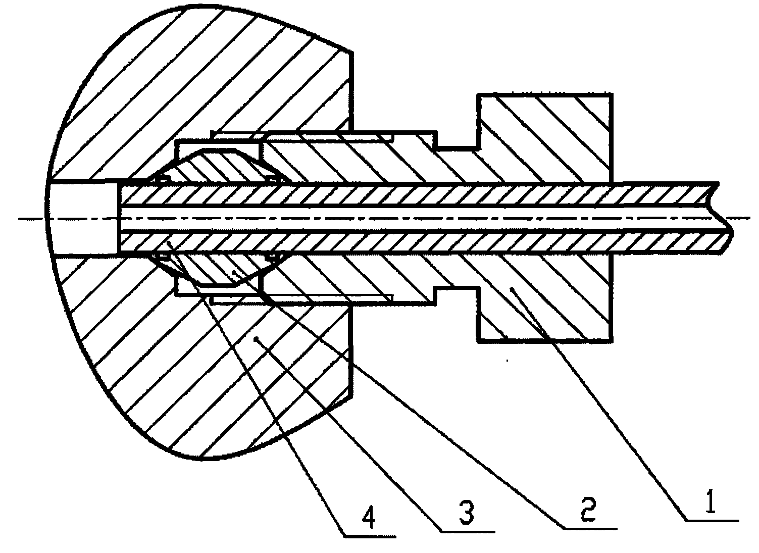
图1为卡套式管接头的示意图;Figure 1 is a schematic diagram of a ferrule-type pipe joint;
图中:1为螺帽、2为卡套、3为接头体,4为被接金属管。In the figure: 1 is a nut, 2 is a ferrule, 3 is a joint body, and 4 is a connected metal pipe.
图2为卡套的剖面图。Figure 2 is a cross-sectional view of the ferrule.
具体实施方式 Detailed ways
参照附图,卡套式管接头包括螺帽1、套筒式卡套2和接头体3,螺帽1的端部和接头体3的凹台处分别开有锥形凹槽,套筒式卡套2两端外壁呈对称的圆锥形,圆锥形的半椎角α=13°~28°,卡套圆锥形的半锥角与接头体锥形凹槽的半锥角相差1°~3°,套筒两端分别具有环形内凹台,环形凹台面与卡套内壁成直角,凹台深度h=0.3~0.7mm,套筒内壁的半径与凹台的半径差值c=0.2~0.4mm,套筒圆锥形顶端的半径与凹台的半径差值b=0.2~0.4mm。Referring to the accompanying drawings, the ferrule-type pipe joint includes a nut 1, a sleeve-
安装时,先将螺帽1、卡套2依次套在金属管4的端部,再一起插入接头体3中,用手拧紧螺帽。拆卸时先将螺帽拧下,再将金属管和套接在其外的卡套一同取下即可,此管接头可重复实用多次。对10个卡套式管接头进行试验,结果表明,在拆装5次之后,打压至70MPa时仍能够达到非常好的密封效果。而传统的卡套式管接头在进行相同的试验时,常会有泄漏现象出现。During installation, the nut 1 and the
Claims (1)
Priority Applications (1)
| Application Number | Priority Date | Filing Date | Title |
|---|---|---|---|
| CN2009201204918U CN201434164Y (en) | 2009-05-21 | 2009-05-21 | Ferrule type pipe joint |
Applications Claiming Priority (1)
| Application Number | Priority Date | Filing Date | Title |
|---|---|---|---|
| CN2009201204918U CN201434164Y (en) | 2009-05-21 | 2009-05-21 | Ferrule type pipe joint |
Publications (1)
| Publication Number | Publication Date |
|---|---|
| CN201434164Y true CN201434164Y (en) | 2010-03-31 |
Family
ID=42052972
Family Applications (1)
| Application Number | Title | Priority Date | Filing Date |
|---|---|---|---|
| CN2009201204918U Expired - Fee Related CN201434164Y (en) | 2009-05-21 | 2009-05-21 | Ferrule type pipe joint |
Country Status (1)
| Country | Link |
|---|---|
| CN (1) | CN201434164Y (en) |
Cited By (1)
| Publication number | Priority date | Publication date | Assignee | Title |
|---|---|---|---|---|
| CN112033807A (en) * | 2020-09-03 | 2020-12-04 | 贵州大学 | Device and test method for auxiliary application of non-uniform pore pressure field in rock specimen |
-
2009
- 2009-05-21 CN CN2009201204918U patent/CN201434164Y/en not_active Expired - Fee Related
Cited By (1)
| Publication number | Priority date | Publication date | Assignee | Title |
|---|---|---|---|---|
| CN112033807A (en) * | 2020-09-03 | 2020-12-04 | 贵州大学 | Device and test method for auxiliary application of non-uniform pore pressure field in rock specimen |
Similar Documents
| Publication | Publication Date | Title |
|---|---|---|
| UA94640C2 (en) | Tightened threaded joint of oil-field tubes | |
| CN101561063A (en) | Ferrule type pipe connector | |
| RS63058B1 (en) | 4-round thread form | |
| CN204785169U (en) | Pipeline connecting structure | |
| CN201265370Y (en) | Gas-tight drill rod connector | |
| CN104806826A (en) | Clamp ring two-side-locked thin-walled metal pipe intertubular connecting component | |
| CN205207964U (en) | Composite connection coupling | |
| CN204372391U (en) | A kind of pressure test pipeline conversion adapter | |
| CN201892605U (en) | External-clamping end face seal type water-pressure tester for small-bore internal screw pipe | |
| CN204677848U (en) | The special Self-fastening high pressure joint of a kind of high pressure needle valve | |
| CN205991263U (en) | Pipe joint arrangement | |
| CN211398861U (en) | A high-strength stainless steel seamless steel pipe | |
| CN209856550U (en) | A steel pipe joint | |
| CN205938250U (en) | Diesel engine oil way pipeline connecting device | |
| CN202176275U (en) | API (American Petroleum Institute) petroleum sleeve threaded connecting structure for preventing flow field induced corrosion and improving sealing property | |
| CN202719311U (en) | A direct push connection pipe joint and a direct push connection pipe joint structure | |
| CN205173786U (en) | Three leaf reducing oil filter piecing devices | |
| CN202501127U (en) | Improved pipeline connecting structure | |
| CN204592625U (en) | Link between the thin metallic tubd pipe of a kind of snap ring bilateral locking | |
| CN205207967U (en) | Connection pipe joint | |
| CN206592700U (en) | A kind of reusable end sealing device | |
| CN106090472B (en) | A kind of diesel engine oil-way assembling pipe joint | |
| CN103292089A (en) | Pipe-end port structure for high-pressure delivery pipelines | |
| CN204300554U (en) | A kind of flared type cone sealing threaded pipe joints of high temperature high voltage resistant | |
| CN205298888U (en) | Pipe -line system sealing joint |
Legal Events
| Date | Code | Title | Description |
|---|---|---|---|
| C14 | Grant of patent or utility model | ||
| GR01 | Patent grant | ||
| C17 | Cessation of patent right | ||
| CF01 | Termination of patent right due to non-payment of annual fee |
Granted publication date: 20100331 Termination date: 20130521 |