CN201389572Y - Pipe cold extrusion reducing device - Google Patents
Pipe cold extrusion reducing device Download PDFInfo
- Publication number
- CN201389572Y CN201389572Y CN200920127219U CN200920127219U CN201389572Y CN 201389572 Y CN201389572 Y CN 201389572Y CN 200920127219 U CN200920127219 U CN 200920127219U CN 200920127219 U CN200920127219 U CN 200920127219U CN 201389572 Y CN201389572 Y CN 201389572Y
- Authority
- CN
- China
- Prior art keywords
- die
- flange
- cold extrusion
- mould
- reducing device
- Prior art date
- Legal status (The legal status is an assumption and is not a legal conclusion. Google has not performed a legal analysis and makes no representation as to the accuracy of the status listed.)
- Expired - Fee Related
Links
Images


Abstract
The utility model discloses a pipe cold extrusion reducing device which comprises a working platform, a hydraulic cylinder and a die, wherein the die and the hydraulic cylinder are coaxially respectively fixedly connected on the upper plane and the lower plane of the working platform, the die comprises a die flap, a die sleeve and a flange, wherein the die sleeve is in a cylinder shape, the periphery of the tube wall of the die sleeve is evenly distributed with guiding grooves, guiding shaft lines of the guiding grooves are crossed with the shaft lines of the die sleeve to form an included angle of 2.5-30 degrees, the guiding grooves and a guide rail arranged on the rear portion of the die flap are matched in a sliding way, the front portion of the die flap is arranged in a middle cavity of the die sleeve, the shaping surface on the front end of the die flap forms the complete outer contour surface of a workpiece reducing shaping segment, the die flap is moveably connected with the flange arranged on the lower portion, and the flange and a piston rod of the hydraulic cylinder are coaxially and fixedly connected. The pipe cold extrusion reducing device is suitable for the cold extrusion reducing of a pipe end cap or a pipe middle segment, compared with the prior art, the pipe cold extrusion reducing device has the advantages of little investment, small occupied space, simple structure, convenient operation, safe use, high product shaft degree, little processing allowance, small inner stress, high working efficiency and long die service span.
Description
Technical field
The utility model relates to a kind of cold extrusion device, particularly a kind of pipe cold extrusion reducing device.
Background technology
The cold extrusion device of existing pipe termination undergauge normally on the common apparatus of four post press, utilizes two oil cylinders to finish the cold extrusion and the demoulding of workpiece, one of them oil cylinder extruding, and another oil cylinder is used for the demoulding.Chinese patent publication number: CN2637027, open September 1 2004 date, invention and created name " makes the extrusion equipment of pipe end reducing ", a kind of extrusion equipment that is used for the pipe end reducing is disclosed, though this equipment only pushes and the demoulding with an oil cylinder, be used for the workpiece clamping but be provided with an oil cylinder in addition.Above-mentioned cold extrusion device or equipment are owing to have two oil cylinders, cause that equipment or device volume are big, energy consumption is high, floor space is big, equipment investment is big, efficient is low, and inconvenient operation, and have certain potential safety hazard, the undergauge product axiality of being pushed simultaneously, is not high, allowance is big.
In addition, the big workpiece cold extrusion of the little two ends of diameter, existing pipe stage casing diameter, usually adopt following dual mode to realize, a kind of mode is to select the pipe material of diameter near the stage casing diameter for use, operation break-down obtains the big pipe workpiece of the little two ends of stage casing diameter diameter to the two ends enlarging on hydraulic press, though this mode mould structure is simple, activity time is long, production efficiency is low, and directly there is the hidden danger of quality of opening crackle in the big straight section in two ends; Another kind of mode is, adopt the round steel material to forge or the mode of cold, warm jumping-up with the two ends enlarged-diameter, process through hole with the processing mode of deflashing in the center again, this mode complex procedures, activity time is long, production efficiency is low, and wastes raw material; Simultaneously, this mode equipment needed thereby is more, and the production site area is big, and investment is high, and above aspects causes the manufacturing cost height.
Chinese patent publication number: CN200963642, open October 24 2007 date, invention and created name " is squeezed into pipe the cold extrusion device of tubular member ", a kind of patented technology that pipe is squeezed into the cold extrusion device of tubular member of my application is disclosed, in actual production process, this technology is utilized the cold extrusion device of the two oil cylinder press of four posts, there are production cost height, equipment energy consumption height, production efficiency is undesirable, simultaneously, also there are potential safety hazard, the product axiality is not high, allowance is big deficiency.
Summary of the invention
The purpose of this utility model is exactly at the deficiencies in the prior art, to the further improvement of " pipe being squeezed into the cold extrusion device of tubular member " and perfect, a kind of easy to operate, safety is provided, invest little, floor space is few, production efficiency is high, and product axiality height, allowance are little, and internal stress is little, imperforation crackle hidden danger of quality, both can finish pipe termination undergauge, also can realize the pipe cold extrusion reducing device of pipe stage casing undergauge.
For achieving the above object, the utility model adopts following technical scheme:
A kind of pipe cold extrusion reducing device comprises workbench, oil cylinder, mould, and it is characterized in that: described oil cylinder is fixedly connected on the workbench lower plane, and mould is fixedly connected on plane on the workbench, and with the oil cylinder coaxial line; Described mould comprises mould lobe, die sleeve, flange, and it is cylindric that die sleeve is, and the barrel of die sleeve is evenly distributed in gathering sill, and the guidance axis of gathering sill becomes the α angle with the die sleeve axes intersect, and the size of α angle is 2.5~30 °; The guide rail at gathering sill and mould lobe rear portion is slidingly matched, and the front portion of mould lobe is arranged in the cavities of die sleeve, and the outline of the forming surface of mould lobe front end and workpiece undergauge profiled section adapts, and the forming surface of all mould lobes constitutes the complete outer surface of workpiece undergauge profiled section; Flange is positioned at mould lobe below, and mould lobe and flange flexibly connect, and flange is fixedlyed connected with the piston rod coaxial line that oil cylinder is provided with.
Adopt the pipe cold extrusion reducing device of above technical scheme, the oil cylinder piston bar drives the mould lobe and moves up and down, because the effect of gathering sill, when the mould lobe moves, its all mould lobes inwardly shrink synchronously or expand outwardly synchronously, the forming surface of lobe mould is finished combination or is decomposed, realize the moulding and the demoulding of workpiece, the workpiece of institute's extrusion modling both can be a pipe termination undergauge, it also can be pipe stage casing undergauge, realized that an oil cylinder finishes the purpose of the cold extrusion shaped and demoulding of workpiece, institute's extruded product axiality is good, allowance is little, the hidden danger of quality of imperforation crackle, the production efficiency height.
Preferably, the angle of cut α of the guidance axis of gathering sill and die sleeve axes intersect is 10~22.5 °, to finish the cold extrusion to pipe spare gradually, guarantees product quality and die life; α too hour, the impulse stroke of extrusion modling is long, the systolic pressure of crimp is less, is unfavorable for extrusion modling, and mold height is higher, the die manufacturing cost height; When α was too big, mould lobe and die sleeve radial force were big, caused mould to damage easily.
Preferably, gathering sill is a kind of in " T type groove " or " dovetail groove " version, can shrink or the expansion required drive by reliable delivery mould lobe, guarantees mould strength and service life.
Further preferred, gathering sill is " dovetail groove " version, further guarantees mould strength and service life.
Preferably, the movable connection method of mould lobe and flange is connected mode a kind of of following three kinds of structures: being slidingly matched and being similar to " dove-tail form " or being slidingly matched of " T font " structure of being slidingly matched of " dove-tail form " structure, " T font " structure, guarantee that when the oil cylinder piston bar moves up and down push-and-pull mould lobe moves up and down reliably, simultaneously, satisfying the mould lobe radially successfully shrinks or expansion.
Further preferred, the movable connection method of mould lobe and flange is for being similar to being slidingly matched of " T font " structure, comprise that the kidney slot on shouldered tap bolt, the flange constitutes, the bar portion of shouldered tap bolt is passed from the kidney slot of flange, is connected on the mould lobe by threaded engagement, and the shoulder of shouldered tap bolt is positioned at outside the lower surface of flange, its shoulder diameter is greater than the width of kidney slot, under the prerequisite that satisfies mould lobe motion requirement, simple in structure, low cost of manufacture.
Preferably, the excircle of die sleeve is provided with the outer die casing of interference fit, and is connected with workbench by outer die casing, reduces die deformation, further prolongs die life, and simultaneously, during die sleeve, outer die casing can also continue to utilize, the reduction die manufacturing cost in changing.
Preferably, the quantity of gathering sill is 3~12, and the quantity of mould lobe equates that with gathering sill quantity when guaranteeing mould strength, the surface of reducing workpiece undergauge section weighs wounded, guarantees the surface of the work polishing, reduces internal stress.
Preferably, the quantity of gathering sill is 8, further guarantees die life and product quality; Gathering sill quantity is very few, the corresponding minimizing of mould lobe quantity, and the undergauge section surface of workpiece easily produces impression or weighs wounded, so there is the hidden danger of quality of internal stress in product; On the contrary, gathering sill quantity is too much, the corresponding increase of mould lobe quantity, and reduce die life.
Adopt the utility model pipe cold extrusion reducing device of technique scheme, finish workpiece cold extrusion and knockout course by an oil cylinder, both be applicable to pipe termination undergauge, also can be used for pipe stage casing undergauge, and need not compress, mould no hydraulic jack in top and relevant pressurizing unit block.The utility model beneficial effect compared with prior art is, invest little, floor space is few, simple in structure, easy to operate, safe in utilization, product axle degree height, allowance is little, internal stress is little, high efficiency, die life are long.
Description of drawings
Fig. 1 is the clamped condition schematic diagram of the utility model embodiment 1 pipe termination cold extrusion reducing;
Fig. 2 is the vertical view of the Fig. 1 among the utility model embodiment 1;
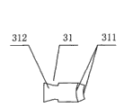
Fig. 3 is the A portion view among the utility model embodiment 1 Fig. 2;
Fig. 4 is the structural representation of mould lobe among the utility model embodiment 1;
Fig. 5 is that B among the utility model embodiment 1 Fig. 4 is to view;
Fig. 6 is the product schematic diagram of the utility model embodiment 1;
Fig. 7 is the pipe tubing blank schematic diagram of the utility model embodiment 1;
Fig. 8 is the C-C cutaway view among the utility model embodiment 1 Fig. 1;
Fig. 9 is the unlocking element view of the utility model embodiment 1;
Figure 10 is the clamped condition schematic diagram of the utility model embodiment 2 pipe stage casing cold extrusion reducings;
Figure 11 is the vertical view of Fig. 9 among the utility model embodiment 2;
Figure 12 is the D portion view among the utility model embodiment 2 Figure 10;
Figure 13 is the mould valve structure schematic diagram of the utility model embodiment 2;
Figure 14 is that the E of Figure 12 among the utility model embodiment 2 is to view;
Figure 15 is the product schematic diagram of the utility model embodiment 2;
Figure 16 is the pipe tubing blank schematic diagram of the utility model embodiment 2;
Figure 17 is that the gathering sill of the utility model die sleeve adopts the structural representation of " T type groove ";
Figure 18 is that the utility model mould lobe and flange type of attachment adopt the structural representation of " dovetail groove ";
Figure 19 is that the utility model mould lobe and flange type of attachment adopt the structural representation of " T type groove ".
The specific embodiment is further described the utility model below in conjunction with accompanying drawing, but therefore the utility model is not limited among the following embodiment:
Referring to Fig. 1, the angle of cut α of the guidance axis of described gathering sill 321 and die sleeve 32 axes intersect is 10~22.5 °.
Referring to Fig. 3, Fig. 5, Figure 17, described gathering sill 321 is a kind of in " T type groove " or " dovetail groove " version.
Referring to Fig. 3, described gathering sill 321 is " dovetail groove " version.
Referring to Fig. 8, Figure 18, Figure 19, the movable connection method of described mould lobe 31 and flange 33 is connected mode a kind of of following three kinds of structures: being slidingly matched and being similar to " dove-tail form " or being slidingly matched of " T font " structure of being slidingly matched of " dove-tail form " structure, " T font " structure.
Referring to Fig. 8, described mould lobe 31 is slidingly matched for the structure that is similar to " T font " with the movable connection method of flange 33, comprise that the kidney slot 331 on shouldered tap bolt 34, the flange 33 constitutes, the bar portion of shouldered tap bolt 34 is passed from the kidney slot 331 of flange 33, be connected on the mould lobe 31 by threaded engagement, the shoulder of shouldered tap bolt 34 is positioned at outside the lower surface of flange 33, and its shoulder diameter is greater than the width of kidney slot 331.
Referring to Fig. 1, the excircle of described die sleeve 32 is provided with the outer die casing 322 of interference fit, and is connected with workbench 1 by outer die casing 322.
Referring to Fig. 1, the quantity of described gathering sill 321 is 8, and the quantity of mould lobe 31 equates with gathering sill 321 quantity.
Referring to Figure 10, the angle of cut α of the guidance axis of described gathering sill 321 and die sleeve 32 axes intersect is 10~22.5 °.
Referring to Figure 12, Figure 14, Figure 17, described gathering sill 321 is a kind of in " T type groove " or " dovetail groove " version.
Referring to Figure 12, described gathering sill 321 is " dovetail groove " version.
Referring to Fig. 8, Figure 18, Figure 19, the movable connection method of described mould lobe 31 and flange 33 is connected mode a kind of of following three kinds of structures: being slidingly matched and being similar to " dove-tail form " or being slidingly matched of " T font " structure of being slidingly matched of " dove-tail form " structure, " T font " structure.
Referring to Fig. 8, described mould lobe 31 is slidingly matched for the structure that is similar to " T font " with the movable connection method of flange 33, comprise that the kidney slot 331 on shouldered tap bolt 34, the flange 33 constitutes, the bar portion of shouldered tap bolt 34 is passed from the kidney slot 331 of flange 33, be connected on the mould lobe 31 by threaded engagement, the shoulder of shouldered tap bolt 34 is positioned at outside the lower surface of flange 33, and its shoulder diameter is greater than the width of kidney slot 331.
Referring to Figure 10, the excircle of described die sleeve 32 is provided with the outer die casing 322 of interference fit, and is connected with workbench 1 by outer die casing 322.
Referring to Figure 10, the quantity of described gathering sill 321 is 8, the quantity of mould lobe 31 and gathering sill 321 quantity etc.
Operation principle briefly explains below in conjunction with the termination cold extrusion reducing process of the embodiment 1 motorcycle direction conical riser operation principle to the utility model pipe cold extrusion reducing device:
A kind of pipe termination cold extrusion reducing device that is used for round tube 51 is squeezed into motorcycle direction conical riser 5, its course of work is as follows:
Referring to Fig. 1, Fig. 6, Hydraulic Station 4 starts " work ", Hydraulic Station 4 is by oil-out 41 injection pressure oil in the oil pocket 23 of oil cylinder 2, simultaneously, oil return opening 42 is to Hydraulic Station 4 tank drainbacks, promote piston, move on piston rod 21 and the flange 33, move on 8 mould lobes 31 that flange 33 promotes to be close to and the tubular blank 51,8 mould lobes 31 slide along 8 dovetail grooves 321 of die sleeve 32 respectively, because the angle α that dovetail groove 321 guidance axis and mould 3 axis constitute, when being moved up, inwardly shrink 8 mould lobes 31, the bar portion of shouldered tap bolt 34 slides in the kidney slot 331 of flange 33, after the forming surface 311 of 8 mould lobes 31 is combined into the cavity surface that complete and motorcycle direction conical riser 5 adapt, oil cylinder 2 quits work, finish extruding, form the motorcycle direction conical riser 5 of termination undergauge motorcycle direction conical riser blank 51.
Referring to Fig. 1, Fig. 7, Fig. 8, Fig. 9, during Hydraulic Station 4 " backhaul ", Hydraulic Station 4 is by oil return opening 42 injection pressure oil in the oil pocket 22 of oil cylinder 2, oil-out 41 is to Hydraulic Station 4 tank drainbacks, promote piston, piston rod 21 and flange 33 move down, motorcycle direction conical riser 5 moves down with flange 33, simultaneously, flange 33 is moved down by 8 mould lobes 31 of 8 shouldered tap bolts, 34 drives of 8 mould lobe 31 lower ends, 8 mould lobes 31 slide along 8 dovetail grooves 321 of die sleeve 32 respectively, and 8 mould lobes 31 expand outwardly when moving down, and the bar portion of 8 shouldered tap bolts 34 slides in 8 kidney slots 331 of flange 33 respectively, realize the demoulding of motorcycle direction conical riser 5, when piston rod 21 and flange 33 bounced back to bottom dead centre, oil cylinder quit work, at this moment, just can take off motorcycle direction conical riser 5 easily, finish a working cycles.If again motorcycle direction conical riser blank 51 is put into the cavity that 8 mould lobes 31 form this moment, be supported on flange 33 upper surfaces, can enter next working cycles.
The working cycles control of Hydraulic Station can be adopted pressure control, also can adopt travel switch control, but all belong to prior art, does not repeat them here.
Claims (9)
1, a kind of pipe cold extrusion reducing device, comprise workbench (1), oil cylinder (2), mould (3), it is characterized in that: described oil cylinder (2) is fixedly connected on workbench (1) lower plane, and mould (3) is fixedly connected on workbench (1) and goes up the plane, and with oil cylinder (2) coaxial line; Described mould (3) comprises mould lobe (31), die sleeve (32), flange (33), die sleeve (32) is cylindric, the barrel of die sleeve (32) is evenly distributed in gathering sill (321), and the guidance axis of gathering sill (321) becomes the α angle with die sleeve (32) axes intersect, and the size of α angle is 2.5~30 °; Gathering sill (321) is slidingly matched with the guide rail (312) at mould lobe (31) rear portion, the front portion of mould lobe (31) is arranged in the cavities of die sleeve (32), the forming surface (311) of mould lobe (31) front end adapts with the outline of workpiece undergauge profiled section, and the forming surface (311) of all mould lobes (31) constitutes the complete outer surface of workpiece undergauge profiled section; Flange (33) is positioned at mould lobe (31) below, and mould lobe (31) flexibly connects with flange (33), and flange (33) is fixedlyed connected with piston rod (21) coaxial line that oil cylinder (2) is provided with.
2, pipe cold extrusion reducing device according to claim 1 is characterized in that: the angle of cut α of the guidance axis of described gathering sill (321) and die sleeve (32) axes intersect is 10~22.5 °.
3, pipe cold extrusion reducing device according to claim 1 is characterized in that: described gathering sill (321) is a kind of in " T type groove " or " dovetail groove " version.
4, pipe cold extrusion reducing device according to claim 3 is characterized in that: described gathering sill (321) is " dovetail groove " version.
5, pipe cold extrusion reducing device according to claim 1 is characterized in that: the movable connection method of described mould lobe (31) and flange (33) is connected mode a kind of of following three kinds of structures: being slidingly matched and being similar to " dove-tail form " or being slidingly matched of " T font " structure of being slidingly matched of " dove-tail form " structure, " T font " structure.
6, pipe cold extrusion reducing device according to claim 5, it is characterized in that: described mould lobe (31) is to be similar to being slidingly matched of " T font " structure with the movable connection method of flange (33), comprise that the kidney slot (331) on shouldered tap bolt (34), the flange (33) constitutes, the bar portion of shouldered tap bolt (34) is passed from the kidney slot (331) of flange (33), be connected on the mould lobe (31) by threaded engagement, the shoulder of shouldered tap bolt (34) is positioned at outside the lower surface of flange (33), and its shoulder diameter is greater than the width of kidney slot (331).
7, pipe cold extrusion reducing device according to claim 1 is characterized in that: the excircle of described die sleeve (32) is provided with the outer die casing (322) of interference fit, and is connected with workbench (1) by outer die casing (322).
8, pipe cold extrusion reducing device according to claim 1, it is characterized in that: the quantity of described gathering sill (321) is 3~12, the quantity of mould lobe (31) equates with gathering sill (321) quantity.
9, pipe cold extrusion reducing device according to claim 8, it is characterized in that: the quantity of described gathering sill (321) is 8.
Priority Applications (1)
| Application Number | Priority Date | Filing Date | Title |
|---|---|---|---|
| CN200920127219U CN201389572Y (en) | 2009-05-05 | 2009-05-05 | Pipe cold extrusion reducing device |
Applications Claiming Priority (1)
| Application Number | Priority Date | Filing Date | Title |
|---|---|---|---|
| CN200920127219U CN201389572Y (en) | 2009-05-05 | 2009-05-05 | Pipe cold extrusion reducing device |
Publications (1)
| Publication Number | Publication Date |
|---|---|
| CN201389572Y true CN201389572Y (en) | 2010-01-27 |
Family
ID=41596391
Family Applications (1)
| Application Number | Title | Priority Date | Filing Date |
|---|---|---|---|
| CN200920127219U Expired - Fee Related CN201389572Y (en) | 2009-05-05 | 2009-05-05 | Pipe cold extrusion reducing device |
Country Status (1)
| Country | Link |
|---|---|
| CN (1) | CN201389572Y (en) |
Cited By (23)
| Publication number | Priority date | Publication date | Assignee | Title |
|---|---|---|---|---|
| CN102601178A (en) * | 2012-02-24 | 2012-07-25 | 宁波拓普集团股份有限公司 | Tube diameter finishing device |
| CN103008486A (en) * | 2012-12-03 | 2013-04-03 | 镇江市恒源汽车零部件有限公司 | Pipe fitting flaring sizing mill |
| CN103124603A (en) * | 2010-08-06 | 2013-05-29 | 美国润滑棒公司 | Hand held flaring tool |
| CN103182459A (en) * | 2013-03-21 | 2013-07-03 | 镇江市恒源汽车零部件有限公司 | Pipe fitting sizing mould |
| CN103302194A (en) * | 2013-06-19 | 2013-09-18 | 广州大峰精密工业有限公司 | Processing technique of hush pipe |
| CN104213705A (en) * | 2014-09-05 | 2014-12-17 | 何华强 | High-perpendicularity scaffold with safe ladders and upright rod manufacturing process |
| CN104511537A (en) * | 2014-11-14 | 2015-04-15 | 镇江利奥排气技术有限公司 | Eight-flap middle-narrowing die |
| CN104826885A (en) * | 2015-05-28 | 2015-08-12 | 成都宏明双新科技股份有限公司 | Machining method for radial forming of thin-wall pipes |
| CN104858309A (en) * | 2015-05-28 | 2015-08-26 | 成都宏明双新科技股份有限公司 | Radial forming bothway die feeding machining system for thin-walled tubes |
| CN105127316A (en) * | 2015-09-18 | 2015-12-09 | 重庆金仑机械制造有限责任公司 | Pipe end reduction device and reduction machining method |
| CN106216444A (en) * | 2016-08-31 | 2016-12-14 | 中国重型机械研究院股份公司 | A kind of for seamless steel pipe end internal-and external diameter diameter-setting equipment |
| CN106623468A (en) * | 2015-10-31 | 2017-05-10 | 常州良旭车辆配件有限公司 | Pipe contracting die and pipe contracting method thereof |
| CN107061405A (en) * | 2016-07-18 | 2017-08-18 | 阜阳市棋剑节能环保设备有限公司 | The dustproof construction of steel pipe size reducing machine hydraulic jack |
| CN108723194A (en) * | 2018-05-02 | 2018-11-02 | 燕山大学 | A kind of building mortion and method of complexity inside and outside wall cylindrical member |
| CN109127927A (en) * | 2017-06-15 | 2019-01-04 | 宝钢工程技术集团有限公司 | Pipe End Throat Machine |
| CN109530495A (en) * | 2018-12-29 | 2019-03-29 | 无锡市振华亿美嘉科技有限公司 | Lock support oral area shaping mould |
| CN110369535A (en) * | 2019-08-08 | 2019-10-25 | 宁波永灵航空科技有限公司 | The processing method and processing mold of workpiece with end-tooth |
| CN110640017A (en) * | 2018-06-27 | 2020-01-03 | 中国石油化工股份有限公司 | Composite material pipe compression molding device and method |
| CN110961864A (en) * | 2019-11-19 | 2020-04-07 | 中国航发贵州黎阳航空动力有限公司 | Forming processing method for oil inlet and oil delivery pipe of aircraft engine |
| CN112170607A (en) * | 2020-08-25 | 2021-01-05 | 重庆志齐机械制造有限公司 | Cold machining process of shock absorber positioning tube |
| US11072018B2 (en) | 2013-10-30 | 2021-07-27 | Ags Company Automotive Solutions Llc | Hand held flaring tool |
| CN113819213A (en) * | 2021-09-22 | 2021-12-21 | 珠海格力电器股份有限公司 | Harmonic reducer ware flexbile gear subassembly and harmonic reducer ware |
| CN114346073A (en) * | 2021-11-29 | 2022-04-15 | 东风商用车有限公司 | Multi-stage correction mechanism and method for controlling post-processing GBD (GBD) reducing cylindricity of engine |
-
2009
- 2009-05-05 CN CN200920127219U patent/CN201389572Y/en not_active Expired - Fee Related
Cited By (34)
| Publication number | Priority date | Publication date | Assignee | Title |
|---|---|---|---|---|
| CN103124603B (en) * | 2010-08-06 | 2015-04-29 | 美国润滑棒公司 | Hand held flaring tool |
| CN103124603A (en) * | 2010-08-06 | 2013-05-29 | 美国润滑棒公司 | Hand held flaring tool |
| US10850319B2 (en) | 2010-08-06 | 2020-12-01 | Ags Company Automotive Solutions, Llc | Hand held flaring tool |
| CN102601178B (en) * | 2012-02-24 | 2014-09-03 | 宁波拓普集团股份有限公司 | Tube diameter finishing device |
| CN102601178A (en) * | 2012-02-24 | 2012-07-25 | 宁波拓普集团股份有限公司 | Tube diameter finishing device |
| CN103008486A (en) * | 2012-12-03 | 2013-04-03 | 镇江市恒源汽车零部件有限公司 | Pipe fitting flaring sizing mill |
| CN103182459A (en) * | 2013-03-21 | 2013-07-03 | 镇江市恒源汽车零部件有限公司 | Pipe fitting sizing mould |
| CN103302194A (en) * | 2013-06-19 | 2013-09-18 | 广州大峰精密工业有限公司 | Processing technique of hush pipe |
| CN103302194B (en) * | 2013-06-19 | 2016-01-20 | 广州大峰精密工业有限公司 | The processing technology of hush pipe |
| US11072018B2 (en) | 2013-10-30 | 2021-07-27 | Ags Company Automotive Solutions Llc | Hand held flaring tool |
| CN104213705A (en) * | 2014-09-05 | 2014-12-17 | 何华强 | High-perpendicularity scaffold with safe ladders and upright rod manufacturing process |
| CN104511537A (en) * | 2014-11-14 | 2015-04-15 | 镇江利奥排气技术有限公司 | Eight-flap middle-narrowing die |
| CN104511537B (en) * | 2014-11-14 | 2016-08-31 | 镇江利奥排气技术有限公司 | A kind of eight lobe waist contracting moulds |
| CN104826885A (en) * | 2015-05-28 | 2015-08-12 | 成都宏明双新科技股份有限公司 | Machining method for radial forming of thin-wall pipes |
| CN104858309A (en) * | 2015-05-28 | 2015-08-26 | 成都宏明双新科技股份有限公司 | Radial forming bothway die feeding machining system for thin-walled tubes |
| WO2016188414A1 (en) * | 2015-05-28 | 2016-12-01 | 成都宏明双新科技股份有限公司 | Radial forming bi-directional die feeding processing system for thin-wall tube |
| CN104826885B (en) * | 2015-05-28 | 2017-05-31 | 成都宏明双新科技股份有限公司 | The processing method that a kind of light-wall pipe is radially molded |
| CN105127316A (en) * | 2015-09-18 | 2015-12-09 | 重庆金仑机械制造有限责任公司 | Pipe end reduction device and reduction machining method |
| CN106623468A (en) * | 2015-10-31 | 2017-05-10 | 常州良旭车辆配件有限公司 | Pipe contracting die and pipe contracting method thereof |
| CN107061405B (en) * | 2016-07-18 | 2018-04-13 | 阜阳市棋剑节能环保设备有限公司 | The dustproof construction of steel pipe size reducing machine hydraulic cylinder |
| CN107061405A (en) * | 2016-07-18 | 2017-08-18 | 阜阳市棋剑节能环保设备有限公司 | The dustproof construction of steel pipe size reducing machine hydraulic jack |
| CN106216444B (en) * | 2016-08-31 | 2018-05-22 | 中国重型机械研究院股份公司 | One kind is used for seamless steel pipe end internal-and external diameter diameter-setting equipment |
| CN106216444A (en) * | 2016-08-31 | 2016-12-14 | 中国重型机械研究院股份公司 | A kind of for seamless steel pipe end internal-and external diameter diameter-setting equipment |
| CN109127927A (en) * | 2017-06-15 | 2019-01-04 | 宝钢工程技术集团有限公司 | Pipe End Throat Machine |
| CN108723194A (en) * | 2018-05-02 | 2018-11-02 | 燕山大学 | A kind of building mortion and method of complexity inside and outside wall cylindrical member |
| CN110640017A (en) * | 2018-06-27 | 2020-01-03 | 中国石油化工股份有限公司 | Composite material pipe compression molding device and method |
| CN110640017B (en) * | 2018-06-27 | 2021-06-22 | 中国石油化工股份有限公司 | Composite material pipe compression molding device and method |
| CN109530495A (en) * | 2018-12-29 | 2019-03-29 | 无锡市振华亿美嘉科技有限公司 | Lock support oral area shaping mould |
| CN110369535A (en) * | 2019-08-08 | 2019-10-25 | 宁波永灵航空科技有限公司 | The processing method and processing mold of workpiece with end-tooth |
| CN110961864A (en) * | 2019-11-19 | 2020-04-07 | 中国航发贵州黎阳航空动力有限公司 | Forming processing method for oil inlet and oil delivery pipe of aircraft engine |
| CN112170607A (en) * | 2020-08-25 | 2021-01-05 | 重庆志齐机械制造有限公司 | Cold machining process of shock absorber positioning tube |
| CN113819213A (en) * | 2021-09-22 | 2021-12-21 | 珠海格力电器股份有限公司 | Harmonic reducer ware flexbile gear subassembly and harmonic reducer ware |
| CN114346073A (en) * | 2021-11-29 | 2022-04-15 | 东风商用车有限公司 | Multi-stage correction mechanism and method for controlling post-processing GBD (GBD) reducing cylindricity of engine |
| CN114346073B (en) * | 2021-11-29 | 2023-10-24 | 东风商用车有限公司 | Multistage correction mechanism and method for controlling post-treatment GBD (GBD) reducing cylindricity of engine |
Similar Documents
| Publication | Publication Date | Title |
|---|---|---|
| CN201389572Y (en) | Pipe cold extrusion reducing device | |
| CN205056771U (en) | A flexible die set for high -pressure forming in three -way pipe | |
| CN101947567A (en) | Processing technique and processing device of flat-head hexagon bolt for cold extrusion shaping cart | |
| CN201366448Y (en) | Backward cold extrusion die for rear stabilizer bar sleeve of car | |
| CN105081096A (en) | Pipe end contraction machining die | |
| CN202316740U (en) | Axle case lute hole stamping and forming machine tool for car drive axle | |
| CN206240959U (en) | A kind of gear shaft splined hole cold extrusion press | |
| CN103949523A (en) | Hydro forming equipment for complex pipe fitting, and application method of equipment | |
| CN103042087B (en) | Process and device for molding small-bore hydraulic bellows | |
| CN206981470U (en) | A kind of shaping mould for short thin-walled tubes part | |
| CN201625733U (en) | Rolled-edge type pipe end socket machine | |
| CN210045778U (en) | Mould of hot extrusion three-way pipe joint blank | |
| CN201482811U (en) | Three-cylinder heading press | |
| CN204338600U (en) | Conical pipe cold-extrusion shaping device | |
| CN111054868A (en) | Device for manufacturing three-way pipe fitting and application thereof | |
| CN107363205B (en) | Forging forming die set of valve body forging piece of flange ball valve with handle | |
| CN212682166U (en) | Vertical spinning system for processing hollow shaft with oil groove | |
| CN102641937A (en) | Y-shaped tee joint forming equipment with support die | |
| CN102274904B (en) | Pairing machine for inner container of water heater | |
| CN201164872Y (en) | Composite mould of motorcycle diverter step-type vertical tube blank | |
| CN201735644U (en) | Middle tube shape forming mechanism for inner container assembling machine of water heater | |
| CN111822576B (en) | Spinning method of hollow shaft with oil groove | |
| CN202162303U (en) | Assembly machine for inner containers of water heaters | |
| CN201423409Y (en) | Die for manufacturing set piston of hydraulic brake pump | |
| CN204953796U (en) | Central siphon hollow tube mold processing |
Legal Events
| Date | Code | Title | Description |
|---|---|---|---|
| C14 | Grant of patent or utility model | ||
| GR01 | Patent grant | ||
| C17 | Cessation of patent right | ||
| CF01 | Termination of patent right due to non-payment of annual fee |
Granted publication date: 20100127 Termination date: 20110505 |