Disclosure of Invention
An object of the utility model is to provide a building structure system and construction method that are assembled by composite building board, it is the novel building structure system that does not establish the beam column in addition, assembles each other by the composite building board that foaming cement, steel frame, structural connection spare and upper and lower surface course constitute.
The technical scheme of the utility model is that:
the utility model discloses a stress function with roof beam among the building structure among the prior art and post is replaced by steel frame's horizontal frame and upright frame in the wallboard completely, and it is through the inside and outside multiple structural connection who sets up of composite building panel, with side fascia, partition plate, floor and roofing board interconnect and the building structure system that forms.
When a certain building or a certain part of the building, beams and columns in a wallboard, a floor slab and a roof slab cannot meet the structural requirements, the wallboard, the floor slab or the roof slab can be mutually connected with an external beam column by mechanical connecting fittings through external beams and columns or connecting pieces such as a plate structure connecting piece for forming a beam and column frame structure, a wall bottom connecting piece, a corner connecting piece, a positioning connecting piece, a floor slab and an external wall slab, a partition board connecting piece, a roof and an external wall, a gable connecting piece, a ridge connecting piece and the like; when the wallboard, the floor slab or the roof panel is applied to buildings with proper welding connection of the external beam columns, the plate structure connecting piece is not needed, and the plate frame is directly welded and connected with the external beam columns.
The utility model discloses a building structure system can use with the big frame system supporting that has the multi-storey building height, for example: the two-storey villa building constructed by the structure system is built on a frame platform with the height of two storeys, so that a construction mode of the air villa is formed.
The utility model discloses a building structure system can make into the side fascia of two layers or height more than two layers according to the building requirement, and in the position of corresponding floor, join in marriage the mode that other panel formed the floor with the steel construction, the implementation scheme completion construction process of floor in replacing this structural system.
The utility model discloses a building structure system also can use in the individual layer building, except that without floor and corresponding connecting piece, other characteristics are unchangeable.
A building structure system assembled by composite building boards is characterized in that: it includes:
the bearing partition wall board and the external wall board which have the functions of building beams and columns are arranged, the frames which play the role of beams and connection are arranged in the floor boards and the roof boards, and the board structure connecting pieces are arranged in the wall boards; and an external structural connector comprising: a wall bottom connection; a corner connector; positioning the connecting piece; floor, external wall panel and partition board connecting pieces; roof and outer wall, gable connecting piece; roof connectors, etc.;
transverse frames, longitudinal frames and plate structure connecting pieces which play the role of beams and columns are arranged in the bearable partition plate and the external wall plate; the floor and the roof board are internally provided with frames which play a role in beam and connection, or are additionally provided with plate structure connecting pieces;
connecting the bearable external wall panel and the bearable partition board containing the in-board structural connecting piece with the wall bottom connecting piece by using a mechanical connecting fitting, so as to realize the connection of the longitudinal frame of the wall board and the foundation;
the corner part is connected by a mechanical connecting fitting through a corner connecting piece;
the transverse frames of the wall board are connected with each other by positioning the positioning connecting pieces and connecting the plate structure connecting pieces with each other;
the frame of the floor slab is connected with the plate structure connecting piece in the wall slab through the connecting piece of the floor slab and the external wall slab and the connecting piece of the floor slab and the partition wall slab, so that the connection of the floor slab, the external wall slab capable of bearing and the partition wall slab capable of bearing is realized;
the roof panel is connected with the bearable partition wall board, the bearable external wall board, the roof panel and the ridge through the roof and gable panel connecting piece, the ridge connecting piece, the roof and external wall board connecting piece and the plate structure connecting piece if necessary.
When the corner of the building wall needs auxiliary connection, the corner auxiliary connecting piece can be adopted for connection; when the adjacent wallboards and roof boards of the building are required to be connected with the floor slab frame in an auxiliary manner, the adjacent wallboards and roof boards can be connected by adopting a flat auxiliary connecting piece.
The utility model relates to a board-like full assembly residential building, it has bearing, antidetonation, thermal-insulated, give sound insulation, energy-efficient, durable, fire-resistant grade integrated performance to accord with the requirement of green building. The utility model discloses can be at on-the-spot rapid Assembly installation, reduced the total cost in house. The utility model discloses can realize that the production of building house integrates, industrialization.
Drawings
Fig. 1 is a schematic structural diagram of an embodiment of the present invention.
Fig. 2 is a schematic view of a part of the structure of the embodiment of the present invention.
Fig. 3 is a schematic view of the connection between the external wall panel and the foundation at the position a in fig. 1.
Fig. 4 is a schematic view illustrating the connection of the external corner of the external wall panel at the position B in fig. 1.
Fig. 5 is a schematic view showing the connection of two external wall panels with a three-panel partition panel at the position C in fig. 1.
Fig. 6 is a schematic view illustrating the connection between the external wall panel and the floor slab at the position D in fig. 1.
Fig. 7 is a schematic view of the connection between the external wall panel and the gable part of the roof panel at the position E in fig. 1.
Fig. 8 is a schematic view of the auxiliary connection of the external corner of the external wall panel at the position F in fig. 1.
Fig. 9 is a schematic view of the auxiliary connection between two external wall panels at the position G in fig. 1.
FIG. 10 is a schematic view showing the connection of two partition plates T at the H position in FIG. 2.
Fig. 11 is a schematic view showing the connection between the upper and lower partition plates and the floor slab at the position L in fig. 2.
Fig. 12 is a schematic view showing the connection of the M-site roof to the ridge portion of the partition wall panel in fig. 2.
Fig. 13 is a schematic view of the connection between the roof and the edge of the external wall panel at the position K in fig. 2.
Fig. 14 is a schematic sectional view of the single partition plate 22 in fig. 2.
Fig. 15 is a schematic sectional view of a single floor slab 23 in fig. 2.
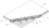
Fig. 16 is a cross-sectional structural view of a single roof panel 24 of fig. 1.
Fig. 17 is a schematic sectional view of the single external wall panel 25 of fig. 1.
Fig. 18 is a schematic structural view of the middle wall bottom connector 4 of the present invention.
Fig. 19 is a schematic structural view of the middle corner connector 5 of the present invention.
Fig. 20 is a schematic structural view of the positioning connector 6 of the present invention.
Fig. 21 is a schematic structural view of the connecting member 8 for connecting the middle floor slab and the external wall slab of the present invention.
Fig. 22 is a schematic structural view of the middle roof and gable connecting member 10 of the present invention.
Fig. 23 is a schematic structural view of the auxiliary connecting member 11 for a middle corner of the present invention.
Fig. 24 is a schematic structural diagram of the middle plate auxiliary connecting member 13 according to the present invention.
Fig. 25 is a schematic structural view of the connecting member 14 for connecting the middle floor slab and the partition wall plate of the present invention.
Fig. 26 is a schematic structural view of the ridge connector 15 of the present invention.
Fig. 27 is a schematic structural view of the middle roof and side fascia connecting member 17 of the present invention.
Fig. 28 is a schematic structural diagram of the middle plate structure connecting member 19 of the present invention.
Detailed Description
The present invention will be further explained with reference to the drawings and the embodiments.
The utility model discloses building structure system, as shown in fig. 1, fig. 2, but it is by bearing partition plate 22 and side fascia 25 that contain building roof beam and post function, sets up inboard structural connection spare in the wallboard at A, B, C, D, E, F, G, H, L, M, K position in floor 23, roof boarding 24 and the picture of board roof beam integration function.
The utility model discloses a through inboard structural connection spare and exterior structural connection spare, it includes: the wall bottom connecting piece, the corner connecting piece, the positioning connecting piece, the floor and external wall panel, the partition wall board connecting piece, the roof and external wall, the gable connecting piece, the ridge connecting piece and other connecting pieces are constructed by connecting the external wall panel 25, the partition wall board 22, the floor 23 and the roof panel 24 together in sequence by adopting mechanical connecting fittings.
The bearable partition wall board 22 and the external wall board 25 are internally provided with a transverse frame 1, a longitudinal frame 2 and a board structure connecting piece 19 which play the roles of beams and columns; the floor 23 and the roof panel 24 are internally provided with a playBeam and connection The acting frames 7 and 9 are additionally provided with plate structure connecting pieces 19 if necessary;
connecting the bearable external wall panel 25 and the bearable partition plate 22 containing the panel structure connecting piece 19 with the wall bottom connecting piece 4 by using the mechanical connecting piece 3 to realize the connection of the wall plate and the foundation; or the wall bottom connecting piece 4 and the bearable wall boards 22 and 25 are connected in advance, and the wall bottom connecting piece 4 is directly welded with the foundation embedded part during construction.
The corner part is connected by the corner connecting piece 5 and the corner auxiliary connecting piece 11 and by the mechanical connecting piece 3 and the auxiliary mechanical connecting fitting 12;
the wallboard is connected with the wallboard through the positioning of the positioning connecting piece 6 and the mutual connection of the plate structure connecting pieces 19;
the frame of the floor slab is connected with the plate structure connecting piece 19 in the wall slab through the floor slab and external wall plate connecting piece 8 and the floor slab and partition plate connecting piece 14, so that the connection of the floor slab 23 with the bearable external wall plate 25 and the bearable partition plate 22 is realized;
the roof panel 24 is connected with the bearable partition wall board 22 and the bearable external wall board 25 through the roof and gable connecting piece 10, the ridge connecting piece 15, the roof and external wall board connecting piece 17 and the board structure connecting piece 19 in the board.
FIG. 3 is a schematic diagram of the A node site: through the mechanical connecting piece 3, the wallboard structure connecting piece 9 and the wallboard bottom connecting piece 4 are connected to complete the connection of the wallboard bottom connecting piece and the wallboard.
Fig. 4 is a schematic diagram of a node B site: the corner wallboard is connected by the corner connecting piece 5 and the mechanical connecting piece 3 and the two wallboard structure connecting pieces 19 respectively.
FIG. 5 is a schematic diagram of a C node site: the plate structure connecting pieces 19 of the three wallboards are connected with each other through the positioning of the positioning connecting pieces 6 and the mechanical connecting pieces 3, and T-shaped connection of the three wallboards is completed.
FIG. 6 is a schematic diagram of the D node location: the floor frame 7 is connected with the wallboard plate structure connecting piece 19 through the mechanical connecting piece 3 and the floor connecting piece 8, and the connection of the floor 23 and the wallboard is completed.
FIG. 7 is a schematic diagram of the E node site: the external wall panel 25 or the partition wall panel 22 is connected with the roof panel 24 through the mechanical connecting piece 3 and the forward connecting piece 10 of the sloping roof and the wall panel, so that the roof panel 24 is connected with the gable panel.
FIG. 8 is a schematic diagram of the F node location: two vertical frames 2 of the wall boards at the corner parts of the male and female walls are constructed, and auxiliary connection of the male and female corner parts of the wall boards is realized by adopting corner auxiliary connecting pieces 11 and auxiliary mechanical connecting fittings 12.
FIG. 9 is a schematic diagram of the G node site: the vertical frame 2 of the two plane-connected wallboards adopts a flat auxiliary connecting piece 13 and an auxiliary mechanical connecting fitting 12 to realize the auxiliary connection of the two wallboards.
FIG. 10 is a schematic diagram of the H node site: the two bearing inner wall boards 22 in the vertical positions connect the transverse frame 1 of the wall board with the plate structure connecting piece 19 on the other wall board through the mechanical connecting piece 3, and the connection of the two plates of the wall board in a T shape is completed.
FIG. 11 is a schematic view of the L node location: the plate structure connecting pieces 19 and the floor frame 7 on the partition wall board are connected through the floor and partition wall board connecting pieces 14 and the mechanical connecting pieces 3, and the connection of two floor slabs 23 and the bearing partition wall board 22 at the bottom layer is completed. And then the connection between the upper layer of wallboard and the floor slab is completed through the connection or welding between the wallboard bottom connecting piece 4 and the mechanical connecting piece 3 of the upper layer and the floor slab frame 7.
Fig. 12 is a schematic diagram of an M node site: the connection between the partition wall board 22 and the roof board 24 and the connection between the two roof boards are completed through the connection between the ridge connecting piece 15 and the mechanical connecting piece 3 and the connection between the plate structure connecting pieces 19 on the partition wall board.
FIG. 13 is a schematic of the K node location: the connecting members 17 and 3 are used to connect the structural members 26 for internal connection between the roof panels and the connecting members 19 on the external wall panels, thereby completing the connection between the roof panels 24 and the external wall panels 25.
Wherein, the inner wall panel 22 can bear the weight, and the wall panel transverse frame 1 and the longitudinal frame 2 are arranged around the panel; and is provided with a plate structure connecting piece 19; a foam cement core material 18 is arranged in the board; and is provided with a cement upper surface layer 20 and a cement lower surface layer 21; the panels are provided with auxiliary structural members 16 and wire mesh 28. As shown in fig. 14.
A floor 23, wherein a floor frame 7 is arranged around the floor; and is provided with a plate structure connecting piece 19; a foam cement core material 18 is arranged in the board; and is provided with a cement upper surface layer 20 and a cement lower surface layer 21; the panels are provided with auxiliary structural members 16 and wire mesh 28. As shown in fig. 15.
A roof panel 24, wherein a roof panel frame 9 is arranged around the panel; and is provided with a plate structure connecting piece 19; a foam cement core material 18 is arranged in the board; and is provided with a cement upper surface layer 20 and a cement lower surface layer 21; the plate is provided with an auxiliary structural member 16, a cold bridge breaking fitting 27 and a steel wire mesh 28. As shown in fig. 16.
The outer wall panel 25 can bear load, and the wallboard frames 1 and 2 are arranged around the panel; and is provided with a plate structure connecting piece 19; a foam cement core material 18 is arranged in the board; and is provided with a cement upper surface layer 20 and a cement lower surface layer 21; the plate is provided with an auxiliary structural member 16, a cold bridge breaking fitting 27 and a steel wire mesh 28. As shown in fig. 17.
The cold bridge cutoff accessory 27 has the function of cutting off cold bridges at the frame positions, and different shapes can be selected according to different requirements; the cold bridge fitting material can be selected from one of the following materials, and comprises: thermal insulation material, wood, plastic section bar, wood-plastic section bar, glass fiber reinforced plastic section bar, phase change energy storage material, and composite material of the above materials and metal material, concrete, cement material, etc.
The foam cement core material 18 is sulphoaluminate cement or a mixture of sulphoaluminate cement and portland cement; or other kinds of cement, or cement with dicalcium silicate, anhydrous calcium sulphoaluminate and dihydrate calcium sulfate as main raw materials or composite cement formed by adding a certain amount of tricalcium silicate into the above-mentioned components as cementing material, and adding foaming agent, modifying agent and powdered solid waste gas, and stirring them and foaming so as to obtain the invented product.
The foam cement core material 18 can also be made of other foam cement, foam gypsum, a mixture of a light heat-insulating material and a cementing material, foam plastic, foam glass, a mixture of cement and a light aggregate; or other organic and inorganic heat-insulating materials; proper fiber materials or organic resins can be added into the foaming cement to increase the toughness; the fiber material can be selected from polymer fiber, glass fiber, carbon fiber or cellulose. The cement upper and lower layers 20 and 21 can be made of one of the following materials: cement, resin cement, modified cement, elastic cement or an organic material as a surface layer.
The in-slab auxiliary structural member 16 has a structural reinforcement effect on the wall panel, the floor panel and the roof panel, and is composed of a steel truss, cold-formed steel, hot-rolled steel, welded steel, a three-dimensional steel wire mesh, a three-dimensional steel bar mesh and the combination of the above materials.
The steel wire mesh 28 in the facing layer is connected with the auxiliary structure connecting pieces 16 in the plate, and has a reinforcing effect on the plate. It is made up by using steel wire mesh, fibre material mesh fabric, cellulose or organic resin and other anti-crack materials with anti-crack action on the surface layer and combining them together.
When the cement surface layers 21 and 22 are made of materials with certain elasticity, crack-resistant materials are not required to be arranged in the surface layers.
The cement surface layers 21 and 22 can be made into various shapes; it can also be made into various colors or used in combination with other decorative materials, and comprises: the wood grain-like, wood-like, ceramic tile-like and stone-like decorative material is made up by using colour cement as surface layer, coating various building coatings on the surface layer, and combining them with wood grain decorative plate, aluminium-plastic plate, glass fibre reinforced plastics and ceramic tile, other metal decorative materials and plastic decorative materials.
The structure of the middle wall bottom connecting piece 4 of the utility model is shown in figure 18.
The structure of the middle corner connecting piece 5 of the present invention is shown in fig. 19.
The structure of the middle positioning connecting piece 6 of the utility model is shown in fig. 20.
The utility model discloses well floor and side fascia connecting piece 8's structure, as shown in figure 21.
The structure of the middle roof and gable connecting piece 10 of the present invention is shown in fig. 22.
The structure of the auxiliary connecting member 11 for a middle corner of the present invention is shown in fig. 23.
The structure of the auxiliary connecting piece 13 for middle flat plate of the present invention is shown in fig. 24.
The structure of the connecting piece 14 for the middle floor slab and the partition wall slab of the utility model is shown in figure 25.
The structure of the middle ridge connector 15 of the present invention is shown in fig. 26.
The structure of the connecting piece 17 for the middle roof and the external wall panel of the utility model is shown in figure 27.
The structure of the middle plate structure connecting piece 19 of the present invention is shown in fig. 28.
In addition, roof panels 24, floor slabs 23, loadable partition panels 22, loadable external wall panels 25, and structural members 26 for in-panel connection may be provided at appropriate locations as needed to facilitate various required connections, such as doors, windows, cornices, weight-hanging embedded parts, and the like.
When the external wall panel, the partition wall panel, the floor panel, and the roof panel are connected, the connection point is not located at the frame position, and the connection point needs to be connected to the structural member 26 for in-panel connection.
When the adjacent wall boards and roof boards of the building are required to be connected with the floor slab frame, the flat auxiliary connecting pieces 13 and the corner auxiliary connecting pieces 11 can be adopted for connection.
The corner parts, the flat joints, the ridge parts and the like of the wallboards, the floor slabs, the roof slabs and the like can be filled with organic or inorganic materials, anti-cracking materials and surface layer materials to realize the edge joint treatment according to different internal and external decoration requirements.
The non-bearing partition plate can be made of porous plate, light steel keel gypsum plate and other materials.
The electric wire threading pipe, the junction box, the water pipe and other devices can be arranged inside the plate in advance according to the requirements of customers.
At the inboard structural connection spare that wallboard, floor, roof boarding set up to and external structure connecting piece, include: the structural form of the plate structure connecting piece, the wall part connecting piece, the corner part connecting piece, the positioning connecting piece, the floor slab and the external wall slab, the partition board connecting piece, the roof and the external wall, the gable connecting piece and the ridge connecting piece can be changed according to the structural requirements of different buildings in the aspects of the thickness, the shape, the strength, the structure, the reinforcing mode and the like of the plate body of the connecting piece.
The steel frame in wall, floor and roof boards may be formed by angle steel, channel steel, cold-formed steel and other steel and truss, or other metal material, or other organic or inorganic material, or concrete frame.
The floor and roof boards are determined whether to add the board structure connecting pieces according to the needs.
The building structure system assembled by composite building boards and the construction method thereof, wherein, the boards of the wall boards, the floor boards and the roof boards can be partially replaced by other boards or construction methods. For example: masonry structures, concrete structures, wood structures, other steel structure wall materials and the like.
The plate can be provided with holes, the door and window can be installed with the plate in advance, and components such as an air conditioner evaporator, a heater, solar energy and the like can also be installed in the plate in advance.
The exterior decoration parts of window lintel, door lintel, bead, false column, etc. of the building can be prefabricated with the plate, and can also adopt the scheme of secondary decoration, such as: the decoration material may be European style member, plaster, hanging stone, ceramic tile, various decoration material, etc.
The plate seam can be pre-provided with a cold bridge prevention device, and can also be processed after the plate is assembled.