CN201347434Y - Steel slag cracking furnace - Google Patents
Steel slag cracking furnace Download PDFInfo
- Publication number
- CN201347434Y CN201347434Y CNU2009200508935U CN200920050893U CN201347434Y CN 201347434 Y CN201347434 Y CN 201347434Y CN U2009200508935 U CNU2009200508935 U CN U2009200508935U CN 200920050893 U CN200920050893 U CN 200920050893U CN 201347434 Y CN201347434 Y CN 201347434Y
- Authority
- CN
- China
- Prior art keywords
- steel slag
- furnace
- furnace body
- air
- cracking furnace
- Prior art date
- Legal status (The legal status is an assumption and is not a legal conclusion. Google has not performed a legal analysis and makes no representation as to the accuracy of the status listed.)
- Expired - Lifetime
Links
- 239000002893 slag Substances 0.000 title claims abstract description 71
- 229910000831 Steel Inorganic materials 0.000 title claims abstract description 66
- 239000010959 steel Substances 0.000 title claims abstract description 66
- 238000005336 cracking Methods 0.000 title claims abstract description 26
- XLYOFNOQVPJJNP-UHFFFAOYSA-N water Substances O XLYOFNOQVPJJNP-UHFFFAOYSA-N 0.000 claims abstract description 22
- 239000007921 spray Substances 0.000 claims abstract description 7
- 230000001939 inductive effect Effects 0.000 claims abstract description 5
- 238000009434 installation Methods 0.000 claims description 3
- 238000005507 spraying Methods 0.000 claims description 2
- 238000010438 heat treatment Methods 0.000 abstract description 4
- 239000002918 waste heat Substances 0.000 abstract description 4
- 238000011084 recovery Methods 0.000 abstract description 3
- 238000004880 explosion Methods 0.000 abstract description 2
- 238000000034 method Methods 0.000 description 12
- 239000000463 material Substances 0.000 description 10
- 239000007769 metal material Substances 0.000 description 10
- 238000001816 cooling Methods 0.000 description 9
- 238000007599 discharging Methods 0.000 description 5
- 239000002184 metal Substances 0.000 description 5
- 229910052751 metal Inorganic materials 0.000 description 5
- 239000003595 mist Substances 0.000 description 4
- 239000011819 refractory material Substances 0.000 description 4
- 239000002689 soil Substances 0.000 description 4
- 238000009413 insulation Methods 0.000 description 3
- 229910001018 Cast iron Inorganic materials 0.000 description 2
- 229910001208 Crucible steel Inorganic materials 0.000 description 2
- 239000011469 building brick Substances 0.000 description 2
- 239000002131 composite material Substances 0.000 description 2
- 239000011810 insulating material Substances 0.000 description 2
- 238000009628 steelmaking Methods 0.000 description 2
- 238000009825 accumulation Methods 0.000 description 1
- 230000007547 defect Effects 0.000 description 1
- 238000001035 drying Methods 0.000 description 1
- 230000005484 gravity Effects 0.000 description 1
- 238000007885 magnetic separation Methods 0.000 description 1
- 229910052755 nonmetal Inorganic materials 0.000 description 1
- 230000000737 periodic effect Effects 0.000 description 1
- 230000008092 positive effect Effects 0.000 description 1
- 238000000926 separation method Methods 0.000 description 1
- 238000010025 steaming Methods 0.000 description 1
- 230000035882 stress Effects 0.000 description 1
- 230000008646 thermal stress Effects 0.000 description 1
Images


Classifications
-
- C—CHEMISTRY; METALLURGY
- C21—METALLURGY OF IRON
- C21B—MANUFACTURE OF IRON OR STEEL
- C21B2400/00—Treatment of slags originating from iron or steel processes
- C21B2400/02—Physical or chemical treatment of slags
- C21B2400/022—Methods of cooling or quenching molten slag
- C21B2400/024—Methods of cooling or quenching molten slag with the direct use of steam or liquid coolants, e.g. water
-
- C—CHEMISTRY; METALLURGY
- C21—METALLURGY OF IRON
- C21B—MANUFACTURE OF IRON OR STEEL
- C21B2400/00—Treatment of slags originating from iron or steel processes
- C21B2400/05—Apparatus features
- C21B2400/066—Receptacle features where the slag is treated
- C21B2400/074—Tower structures for cooling, being confined but not sealed
-
- C—CHEMISTRY; METALLURGY
- C21—METALLURGY OF IRON
- C21B—MANUFACTURE OF IRON OR STEEL
- C21B2400/00—Treatment of slags originating from iron or steel processes
- C21B2400/08—Treatment of slags originating from iron or steel processes with energy recovery
-
- Y—GENERAL TAGGING OF NEW TECHNOLOGICAL DEVELOPMENTS; GENERAL TAGGING OF CROSS-SECTIONAL TECHNOLOGIES SPANNING OVER SEVERAL SECTIONS OF THE IPC; TECHNICAL SUBJECTS COVERED BY FORMER USPC CROSS-REFERENCE ART COLLECTIONS [XRACs] AND DIGESTS
- Y02—TECHNOLOGIES OR APPLICATIONS FOR MITIGATION OR ADAPTATION AGAINST CLIMATE CHANGE
- Y02W—CLIMATE CHANGE MITIGATION TECHNOLOGIES RELATED TO WASTEWATER TREATMENT OR WASTE MANAGEMENT
- Y02W30/00—Technologies for solid waste management
- Y02W30/50—Reuse, recycling or recovery technologies
Landscapes
- Furnace Details (AREA)
Abstract
本实用新型涉及钢渣裂解炉,包括炉体,在炉体顶部或上部设置有引气装置和加料门,在炉体中部设有导气梁和喷雾装置,在炉体底部设有锥形斗和出料装置。它能够连续地对温度高达1000℃以上的炽热钢渣进行热焖裂解,钢渣裂解炉底部不可能集水,当装入钢渣时不会发生爆炸事故,钢渣裂解炉炉壁材料工作条件好,无人为的机械损坏,寿命长达5年以上,水从炽热钢渣层底部以蒸汽状由下而上穿过炽热钢渣层首先对其进行速冷,然后再热焖裂解,热焖时间短,焖渣均匀;水消耗量小,出炉后渣的含水量在5%以下;钢渣裂解炉数量少、不需铲车装料、不需挖掘机出料。具有系统投资少、运行费用低、安全可靠度高、并能方便地回收利用炽热钢渣余热的优点。
The utility model relates to a steel slag cracking furnace, which includes a furnace body, an air-inducing device and a feeding door are arranged on the top or upper part of the furnace body, an air-guiding beam and a spray device are arranged in the middle of the furnace body, and a conical bucket and a Discharge device. It can continuously thermally crack hot steel slag with a temperature above 1000°C. It is impossible to collect water at the bottom of the steel slag cracking furnace, and there will be no explosion accidents when steel slag is loaded. The mechanical damage, the service life is more than 5 years, the water passes through the hot steel slag layer from the bottom to the top in the form of steam from the bottom of the hot steel slag layer, firstly cools it quickly, and then heats it for cracking, the heating time is short, and the slag is uniform ; The water consumption is small, and the water content of the slag after being released from the furnace is below 5%; the number of steel slag cracking furnaces is small, and there is no need for forklift loading or excavator discharge. It has the advantages of low system investment, low operating cost, high safety and reliability, and convenient recovery and utilization of hot steel slag waste heat.
Description
【技术领域】 【Technical field】
本实用新型涉及一种钢渣处理装置,尤其是涉及一种钢渣裂解炉。The utility model relates to a steel slag processing device, in particular to a steel slag cracking furnace.
【背景技术】 【Background technique】
钢渣热焖工艺在国内各钢厂得到了普遍利用,其工艺原理是将热态钢渣置于焖罐中,在焖罐中向钢渣表面雾化喷水,使其内外温差过大而产生热应力、蒸压过程中矿相变化而产生相变应力等,使钢渣快速冷却、自然破碎,从而实现了金属和渣的较好分离,之后经多级分级磁选后,将金属料和非金属料分离开来,使之各尽其用。Steel slag hot stewing process has been widely used in various domestic steel mills. The principle of the process is to place hot steel slag in a stewing tank, spray water on the surface of the steel slag in the stewing tank, and make the temperature difference between inside and outside too large to generate thermal stress. , Ore phase changes in the autoclaving process, resulting in phase change stress, etc., so that the steel slag is rapidly cooled and naturally broken, thereby achieving a better separation of metal and slag, and then after multi-stage classification magnetic separation, the metal material and non-metal material Separate and make use of each.
焖罐是钢渣热焖工艺的核心装备,是决定钢渣热焖工艺能否高效、安全、稳定运行的关键,而就目前在用的钢渣热焖装置来说存在的主要问题是:不能够连续地对温度高达1000℃以上的炽热钢渣进行热焖裂解;热焖装置(焖罐)底部容易积水,当装入钢渣时极容易发生爆炸而导致人员伤亡和财产损失;罐底罐壁材料在冷热交替、装出料过程中难免的机械碰撞等多种因素的作用下而频繁地损坏、更换;水从料层上部喷到热态钢渣的表面,只有当表层温度降落后,水才会逐层渗透到料层内部,且焖罐内存在死角,造成热焖时间太长,焖渣均匀性差;水消耗量大,出焖罐后渣的含水量高达15%左右;焖罐数量多、装料需要铲车、天车抓斗、出料需要挖掘机,而造成系统投资过大、运行费用高、安全隐患多。The stewing tank is the core equipment of the steel slag thermal stewing process, and is the key to determine whether the steel slag thermal stewing process can operate efficiently, safely and stably. As far as the steel slag thermal stewing device currently in use is concerned, the main problem is that it cannot continuously Hot steel slag with a temperature of over 1000°C is thermally cracked; the bottom of the thermal braising device (steaming tank) is prone to water accumulation, and when steel slag is loaded, it is very easy to explode and cause casualties and property losses; Frequent damage and replacement due to various factors such as heat alternation and inevitable mechanical collision during loading and unloading; water is sprayed from the upper part of the material layer to the surface of the hot steel slag, and only when the surface temperature drops, the water will gradually The layer penetrates into the material layer, and there are dead corners in the stewing tank, resulting in too long heating time and poor uniformity of the stewed slag; the water consumption is large, and the water content of the slag after leaving the stewed tank is as high as about 15%; Materials need forklifts, crane grabs, and excavators are required for discharging materials, resulting in excessive system investment, high operating costs, and many safety hazards.
【实用新型内容】 【Content of utility model】
为了克服现有技术的上述缺陷,本实用新型提供一种系统投资少、运行费用低、安全可靠度高、并能方便地回收利用炽热钢渣余热的钢渣裂解炉。In order to overcome the above-mentioned defects of the prior art, the utility model provides a steel slag cracking furnace with low system investment, low operating cost, high safety and reliability, and convenient recovery and utilization of hot steel slag waste heat.
本实用新型所采用的技术方案是:一种钢渣裂解炉,包括炉体,在炉体顶部或上部设置有引气装置和加料门,在炉体中部设有导气梁和喷雾装置,在炉体底部设有锥形斗和出料装置。The technical scheme adopted by the utility model is: a steel slag cracking furnace, including a furnace body, an air-inducing device and a feeding door are arranged on the top or upper part of the furnace body, an air-guiding beam and a spray device are arranged in the middle of the furnace body, The bottom of the body is equipped with a conical bucket and a discharge device.
所述炉体是由工作层、隔热层、永久层所组成。The furnace body is composed of a working layer, a heat insulating layer and a permanent layer.
所述炉体部份的永久层包括混凝土、自然土、回填土、钢制炉壳、砌筑炉壳等等,隔热层包括定型与不定型耐火材料、隔热材料、工业渣、耐热混凝土、建筑砖及砌块等,工作层包括定型与不定型耐火材料等非金属材料、也可以是铸铁、铸钢等金属材料;炉体横断面形状为圆形、正方形、长方形等任意一种几何形状,炉体纵断面形状可以是直筒形、花瓶形、哑棱形、锥形和倒锥形等任意一种形状;钢渣裂解炉断面尺寸、高径比及其容积的大小根据炼钢炉的大小而确定。The permanent layer of the furnace body part includes concrete, natural soil, backfill soil, steel furnace shell, masonry furnace shell, etc., and the heat insulation layer includes shaped and unshaped refractory materials, heat insulating materials, industrial slag, heat-resistant Concrete, building bricks and blocks, etc. The working layer includes non-metallic materials such as shaped and unshaped refractory materials, and can also be metal materials such as cast iron and cast steel; the cross-sectional shape of the furnace body is any one of circular, square, rectangular, etc. Geometric shape, the shape of the longitudinal section of the furnace body can be any shape such as straight cylinder, vase shape, dumb prismatic shape, cone shape and inverted cone shape; determined by the size.
所述引气装置用于将炉内蒸汽有序地导出炉外,其上装有安全阀;加料门用于装料入炉,可灵活地开启和关闭。The air-introducing device is used to guide the steam in the furnace out of the furnace in an orderly manner, and a safety valve is installed on it; the charging door is used for charging materials into the furnace, and can be opened and closed flexibly.
所述炉体中部的导气梁是由金属或非金属材料制成,也可以是金属或非金属材料的组合结构,导气梁可以是非冷却结构,也可以是水冷或油冷或空冷结构;其断面形状可以是三角形、正方形、半圆形等任意一种几何形状;导气梁在炉内的安装方式可以是十字、一字、二字、三字、人字、井字、工字、王字等。喷雾装置位于导气梁下方,由供水管和雾化喷头组成。The air-guiding beam in the middle of the furnace body is made of metal or non-metallic materials, or a composite structure of metal or non-metallic materials, and the air-guiding beam can be a non-cooling structure, or a water-cooling, oil-cooling or air-cooling structure; Its cross-sectional shape can be any geometric shape such as triangle, square, and semicircle; the installation method of the air guide beam in the furnace can be cross, one, two, three, herringbone, well, I, and king. wait. The spray device is located under the air guide beam and consists of a water supply pipe and an atomizing nozzle.
所述炉体底部的锥形斗为钢或混凝土,其下部开设有人孔;在炉体底部的出料装置包括有振动给料机、圆盘给料机、皮带给料机等各种类型的给出料设备,也包括直接安装于锥形斗底部的皮带机、链板机、提升机等提升运输设备。The conical bucket at the bottom of the furnace body is made of steel or concrete, and its lower part is provided with a manhole; the discharge device at the bottom of the furnace body includes various types of feeders such as vibrating feeders, disc feeders, and belt feeders. The feeding equipment also includes lifting and transportation equipment such as belt conveyors, chain conveyors, and hoists directly installed at the bottom of the conical bucket.
本实用新型的积极效果是:它能够连续地对温度高达1000℃以上的炽热钢渣进行热焖裂解,钢渣裂解炉底部不可能集水,当装入钢渣时不会发生爆炸事故,钢渣裂解炉炉壁材料工作条件好,不受人为的机械损坏,寿命长达5年以上,水从炽热钢渣层底部以蒸汽状由下而上穿过炽热钢渣层首先对其进行速冷,然后再热焖裂解,且钢渣裂解炉内不存在死角,热焖时间短,焖渣均匀;水消耗量小,出炉后渣的含水量在5%以下;钢渣裂解炉数量少、不需要铲车装料、不需要挖掘机出料,可方便地回收利用炽热钢渣余热。具有系统投资少、运行费用低、安全可靠度高、并能方便地回收利用炽热钢渣余热的优点。The positive effect of the utility model is that it can continuously heat and crack hot steel slag with a temperature as high as 1000°C, and it is impossible to collect water at the bottom of the steel slag cracking furnace, and no explosion accident will occur when steel slag is loaded. The working condition of the wall material is good, free from man-made mechanical damage, and the life span is more than 5 years. Water passes through the hot steel slag layer from the bottom of the hot steel slag layer in the form of steam from bottom to top to quickly cool it first, and then heat it to crack. , and there is no dead angle in the steel slag cracking furnace, the heating time is short, and the slag is uniform; the water consumption is small, and the water content of the slag after the furnace is less than 5%; the number of steel slag cracking furnaces is small, no need for forklift loading, no need The excavator discharges the waste heat of hot steel slag, which can be conveniently recycled. It has the advantages of low system investment, low operating cost, high safety and reliability, and convenient recovery and utilization of hot steel slag waste heat.
【附图说明】 【Description of drawings】
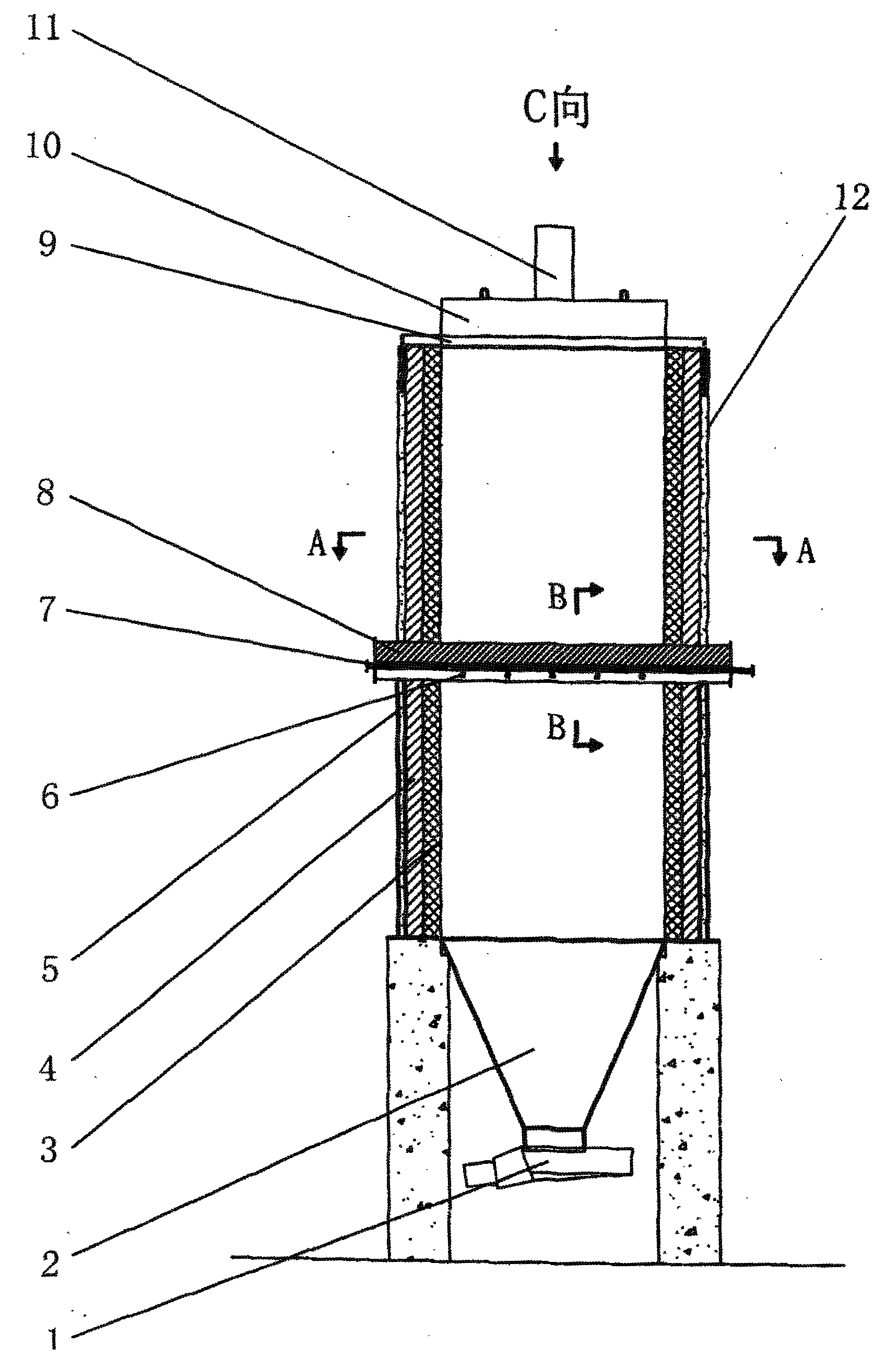
图1是本实用新型的结构示意图;Fig. 1 is the structural representation of the utility model;
图2是图1的A-A剖面图;Fig. 2 is the A-A sectional view of Fig. 1;
图3是图1的B--B剖面图;Fig. 3 is the B--B sectional view of Fig. 1;
图4是图1的C向视图。Fig. 4 is a view from the direction C of Fig. 1 .
图中:1-出料装置,2-锥形斗,3-工作层,4-隔热层,5-永久层,6-雾化喷头,7-供水管,8-导气梁,9-炉顶,10-加料门,11-引气装置,12-炉体。In the figure: 1-discharging device, 2-conical bucket, 3-working layer, 4-heat insulation layer, 5-permanent layer, 6-atomizing nozzle, 7-water supply pipe, 8-air guide beam, 9- Furnace roof, 10-charging door, 11-air-entraining device, 12-furnace body.
【具体实施方式】 【Detailed ways】
下面结合附图和实施例对本实用新型作进一步说明:Below in conjunction with accompanying drawing and embodiment the utility model is further described:
一种钢渣裂解炉,包括炉体12,该炉体12是由工作层3、隔热层4、永久层5所组成;在炉体12顶部或上部设置有引气装置11和加料门10,在炉体12中部设有导气梁8和喷雾装置6,在炉体12底部设有锥形斗2和出料装置1。A steel slag cracking furnace, comprising a
所述炉体12部份的永久层5包括混凝土、自然土、回填土、钢制炉壳、砌筑炉壳等等,隔热层4包括定型与不定型耐火材料、隔热材料、工业渣、耐热混凝土、建筑砖及砌块等,工作层3包括定型与不定型耐火材料等非金属材料、也可以是铸铁、铸钢等金属材料;炉体12横断面形状为圆形、正方形、长方形等任意一种几何形状,炉体12纵断面形状可以是直筒形、花瓶形、哑棱形、锥形和倒锥形等任意一种形状;钢渣裂解炉断面尺寸、高径比及其容积的大小根据炼钢炉的大小而确定。The
所述引气装置11用于将炉内蒸汽有序地导出炉外,其上装有安全阀;加料门10用于装料入炉,可灵活地开启和关闭。The air-inducing
所述炉体12中部的导气梁8是由金属或非金属材料制成,也可以是金属或非金属材料的组合结构,导气梁8可以是非冷却结构,也可以是水冷或油冷或空冷结构;其断面形状可以是三角形、正方形、半圆形等任意一种几何形状;导气梁8在炉内的安装方式可以是十字、一字、二字、三字、人字、井字、工字、王字等。喷雾装置位于导气梁8下方,由供水管7和雾化喷头6组成。The air guiding
所述炉体12底部的锥形斗2为钢或混凝土,其下部开设有人孔;在炉体12底部的出料装置1包括有振动给料机、圆盘给料机、皮带给料机等各种类型的给出料设备,也包括直接安装于锥形斗底部的皮带机、链板机、提升机等提升运输设备。The
工作时,首先开启钢渣裂解炉出料装置1,使炉内料面下降1~2m,将一定量的已经裂解冷却后的钢渣自动排到炉外。然后打开加料门10,由翻罐装置将炽热钢渣直接倒入钢渣裂解炉内,倒料完毕关闭加料门10;开启雾化喷头6和供水管7,在导气梁8的下方由上而下向导气梁8下的料面喷射水雾,水雾与温度为500℃~800℃的中温钢渣相遇而急速蒸发,温度约150℃的蒸汽自下而上地经导气梁8,到达新装入的炽热钢渣层对其进行强制蒸汽速冷,炽热钢渣层温度迅速由1000℃以上降到800℃以下,蒸汽温度则由150℃提高到了300℃以上,由引气装置11将蒸汽有序地导出炉外。When working, first open the discharge device 1 of the steel slag cracking furnace to lower the material level in the furnace by 1 to 2 m, and automatically discharge a certain amount of cracked and cooled steel slag to the outside of the furnace. Then open the
一定时间后,重新开启出料装置1,再次使炉内料面下降1~2m,将一定量的已经裂解冷却后的钢渣自动排到炉外。再次打开加料门10,由翻罐装置将炽热钢渣直接倒入钢渣裂解炉内,倒料完毕关闭加料门10;开启6、7,在导气梁8的下方由上而下向导气梁下的料面喷射水雾,水雾与温度为500℃~800℃的中温钢渣相遇而急速蒸发,温度约150℃的蒸汽自下而上地经导气梁8,到达新装入的炽热钢渣层对其进行强制蒸汽速冷,炽热钢渣层温度迅速由1000℃以上降到800℃以下,蒸汽温度则由150℃提高到了300℃以上,由引气装置11将蒸汽有序地导出炉外。After a certain period of time, the discharge device 1 is reopened to lower the material level in the furnace by 1 to 2 m again, and a certain amount of cracked and cooled steel slag is automatically discharged out of the furnace. Open the charging
如上周期性的装料出料,炽热钢渣由钢渣裂解炉上部在其重力作用下不断向下移动,其在自上而下的移动过程中依次经历了蒸汽速冷、喷雾热焖、冷却干燥等过程。在这一过程中炽热钢渣温度由1000℃以上逐步降低到降到80℃以下后,由出料装置1排到钢渣裂解炉外,产生的高温蒸汽则会源源不断地由引气装置有序地导到炉外,便可方便地回收其热能。As above periodic charging and discharging, the hot steel slag is continuously moved downwards from the upper part of the steel slag cracking furnace under the action of its gravity, and it has successively experienced steam rapid cooling, spray heating, cooling and drying, etc. in the process of moving from top to bottom. process. In this process, after the temperature of the hot steel slag is gradually reduced from above 1000°C to below 80°C, it is discharged from the discharge device 1 to the outside of the steel slag cracking furnace, and the high-temperature steam generated will be continuously and orderly discharged by the air-entraining device. Guided to the outside of the furnace, the heat energy can be recovered conveniently.
装料出料周期与炼钢炉的排渣周期相同,以实现即来渣即入炉,装料过程不用铲车,出料不用挖掘机。The charging and discharging cycle is the same as the slag discharge cycle of the steelmaking furnace, so that the slag can be put into the furnace immediately. The charging process does not require a forklift, and the discharging does not require an excavator.
Claims (8)
Priority Applications (1)
| Application Number | Priority Date | Filing Date | Title |
|---|---|---|---|
| CNU2009200508935U CN201347434Y (en) | 2009-01-23 | 2009-01-23 | Steel slag cracking furnace |
Applications Claiming Priority (1)
| Application Number | Priority Date | Filing Date | Title |
|---|---|---|---|
| CNU2009200508935U CN201347434Y (en) | 2009-01-23 | 2009-01-23 | Steel slag cracking furnace |
Publications (1)
| Publication Number | Publication Date |
|---|---|
| CN201347434Y true CN201347434Y (en) | 2009-11-18 |
Family
ID=41366908
Family Applications (1)
| Application Number | Title | Priority Date | Filing Date |
|---|---|---|---|
| CNU2009200508935U Expired - Lifetime CN201347434Y (en) | 2009-01-23 | 2009-01-23 | Steel slag cracking furnace |
Country Status (1)
| Country | Link |
|---|---|
| CN (1) | CN201347434Y (en) |
Cited By (3)
| Publication number | Priority date | Publication date | Assignee | Title |
|---|---|---|---|---|
| CN106435067A (en) * | 2016-12-15 | 2017-02-22 | 大冶市环宇钙业科技有限公司 | Efficient energy-saving stable type steel slag pyrolyzer |
| CN109628668A (en) * | 2019-01-24 | 2019-04-16 | 韶关市曲江盛大冶金渣环保科技开发有限公司 | Steel slag cracking and residual neat recovering system |
| CN113462830A (en) * | 2021-07-09 | 2021-10-01 | 内蒙古高等级公路建设开发有限责任公司 | A hot steel slag cracking processing device |
-
2009
- 2009-01-23 CN CNU2009200508935U patent/CN201347434Y/en not_active Expired - Lifetime
Cited By (6)
| Publication number | Priority date | Publication date | Assignee | Title |
|---|---|---|---|---|
| CN106435067A (en) * | 2016-12-15 | 2017-02-22 | 大冶市环宇钙业科技有限公司 | Efficient energy-saving stable type steel slag pyrolyzer |
| CN106435067B (en) * | 2016-12-15 | 2018-06-29 | 大冶市环宇钙业科技有限公司 | A kind of energy-efficient stable type steel slag cracking furnace |
| CN109628668A (en) * | 2019-01-24 | 2019-04-16 | 韶关市曲江盛大冶金渣环保科技开发有限公司 | Steel slag cracking and residual neat recovering system |
| CN109628668B (en) * | 2019-01-24 | 2024-04-02 | 韶关市曲江盛大冶金渣环保科技开发有限公司 | Steel slag cracking and waste heat recovery system |
| CN113462830A (en) * | 2021-07-09 | 2021-10-01 | 内蒙古高等级公路建设开发有限责任公司 | A hot steel slag cracking processing device |
| CN113462830B (en) * | 2021-07-09 | 2022-04-29 | 内蒙古高等级公路建设开发有限责任公司 | A hot steel slag cracking processing device |
Similar Documents
| Publication | Publication Date | Title |
|---|---|---|
| CN108866270A (en) | a steelmaking facility | |
| CN210125730U (en) | Heat-preservation steel ladle masonry structure | |
| CN201670844U (en) | An air-cooled crushing device for molten steel slag | |
| CN204999848U (en) | Supporting burnt jar of novel structure of dry coke quenching stove | |
| CN102699301A (en) | Steel continuous casting process for ultra supercritical high-pressure boiler tube | |
| CN212720899U (en) | Submerged arc furnace body structure | |
| CN203096090U (en) | Slag-iron separating device | |
| CN201265017Y (en) | Blast furnace hearth furnace bottom lining structure | |
| CN202164312U (en) | Lining structure for blast furnace slag iron runner cover plate | |
| CN212350352U (en) | a ladle structure | |
| CN103063011B (en) | Energy-saving environment-friendly high-blast-temperature cupola system equipment | |
| CN101693931A (en) | Cooling device at tuyere part of blast furnace | |
| CN205077079U (en) | Cooling wall for "bosh of blast furnace | |
| CN205067396U (en) | Hot modified test device of refining slag | |
| CN204355993U (en) | A kind of New-type hot-air furnace vault manhole repairs hanging apparatus online | |
| CN106435067B (en) | A kind of energy-efficient stable type steel slag cracking furnace | |
| CN203687585U (en) | Vertical continuous aluminum smelting furnace | |
| CN203782176U (en) | Roasting storehouse of furnace charges for smelting steel alloy | |
| CN202182612U (en) | Lining structure of vertical lime pit | |
| CN107699646B (en) | Stainless steel slag granulating device and method | |
| CN205223273U (en) | Composite cooling wall | |
| CN203695941U (en) | Steel ladle working lining | |
| CN205299514U (en) | Rotatory efflux oxygen rifle of supersonic speed and application apparatus | |
| CN203203392U (en) | Novel energy-saving sintering intermediate-frequency furnace | |
| CN204255081U (en) | A kind of EAF bottom ramming mass Rotating fields |
Legal Events
| Date | Code | Title | Description |
|---|---|---|---|
| C14 | Grant of patent or utility model | ||
| GR01 | Patent grant | ||
| CX01 | Expiry of patent term | ||
| CX01 | Expiry of patent term |
Granted publication date: 20091118 |