CN201346032Y - Seat type storage device - Google Patents
Seat type storage device Download PDFInfo
- Publication number
- CN201346032Y CN201346032Y CNU2008201442606U CN200820144260U CN201346032Y CN 201346032 Y CN201346032 Y CN 201346032Y CN U2008201442606 U CNU2008201442606 U CN U2008201442606U CN 200820144260 U CN200820144260 U CN 200820144260U CN 201346032 Y CN201346032 Y CN 201346032Y
- Authority
- CN
- China
- Prior art keywords
- outer case
- antetheca
- opening
- location
- plane materiel
- Prior art date
- Legal status (The legal status is an assumption and is not a legal conclusion. Google has not performed a legal analysis and makes no representation as to the accuracy of the status listed.)
- Expired - Fee Related
Links
Images


Abstract
The utility model relates to a seat type storage device which comprises an outer box and a storage box; the bottom side of the outer box is provided with an upper flexible surface material and a lower flexible surface material which are respectively arranged above and below in a distance; a lower panel is arranged on the upper flexible surface material; both sides of an opening on the lower panel are respectively provided with vertical positioning plates; an upper panel is further arranged on each positioning plate; a cover which can provide a seat can be arranged on the outer box; an opening is arranged on the front wall of the outer box; the storage box can slide in through the opening, and the users can smoothly pull out or push in the storage box when sitting on the cover.
Description
Technical field
The utility model relates to a kind of accommodation device, relates in particular to a kind of chair type accommodation device.
Background technology
Accommodation device on the market is of a great variety at present, but only is divided into fixed and collapsible two kinds haply; Described fixed accommodation device is the skeleton accepting rack that utilizes metal, timber, plastic or other material group to constitute, and its whole volume is fixed, can't be when not using reduced volume so that collection.Described collapsible accommodation device then is such as storage box or article placing cabinet bending structure to be set, so that it can be folded into smaller volume when not using; For example, can utilize flexible cloth coating hard plate and constitute storage box, between two plates, connect and the formation broken line, storage box can be folded into flat flat-shaped by this broken line with described flexible cloth.Another kind of foldable storage box or article placing cabinet then are to utilize hinge to connect adjacent plate, so as to reaching identical folder function.But aforesaid accommodation device all can only be taken in article, and the function of seat is not provided.
The utility model content
Technical problem underlying to be solved in the utility model is, overcomes the above-mentioned defective that prior art exists, and a kind of chair type accommodation device is provided, and it has accommodation device and seat function concurrently.
Based on this, technological means of the present utility model, include an outer case and a storage box, the bottom surface of described outer case is provided with and lays respectively at, below and last flexible plane materiel and time flexible plane materiel with a distance, storing one lower plate on last flexible plane materiel, described opening both sides on this lower plate are provided with a location-plate of erectting respectively, put a upper plate on those location-plates again, one lid that the seat can be provided is set above the outer case, antetheca in outer case is provided with an opening, described storage box can slip into from this opening, and the user still can successfully allow storage box successfully pull out or push when being seated on this lid.
The technological means of described outer case, be to utilize flexible cloth to coat plate, make whole outer case have an antetheca, the two side that connects this antetheca, an and rear wall that connects this two side, this antetheca, rear wall and two side following is connected on one flexible plane materiel and flexible plane materiel once jointly, and should go up flexible plane materiel and have a distance between the flexible plane materiel down, by this apart from constituting aforesaid cushion space, this antetheca, one case mouth of the common formation in the top of rear wall and two side, this antetheca is provided with an opening, be provided with the location-plate of setting in the outer case inside of these opening both sides, by the arrangement for guiding of this two location-plate as these opening both sides.Described lower plate is directly to be placed in above the last flexible plane materiel of outer case, and this location-plate then is located on this lower plate, and upper plate is placed in above the location-plate again.
The technological means of described storage box, also utilize flexible cloth to coat plate, a rear wall that makes whole outer case have an antetheca, connect the two side of this antetheca and connect this two side, so as to forming a folding storage box, this storage box can push from the opening of outer case in the outer case, also storage box can be pulled out from this opening.
For location-plate can firmly be made up with outer case, the utility model is respectively equipped with one first adhesive buckle face at the antetheca medial surface of the opening both sides of outer case with the medial surface of corresponding described rear wall, and two vertical edges of described two location-plates are respectively equipped with the second adhesive buckle face that can bind with this first adhesive buckle face, by the bonding of this first adhesive buckle face and this second adhesive buckle face this two location-plate are fixed in described opening both sides in this outer case.
As seen by above-mentioned, principal character of the present utility model is to make up a storage box in an outer case, and this storage box can move horizontally with respect to this outer case and obtains the effect of taking in article as drawer-like; Cover a lid above the described outer case, this is soft top layer above lid, and its inside can filling expanded material or soft material, makes the integral body can be as comfortable chair.
Another feature of the present utility model is, described outer case and storage box are folding design, it utilizes flexible cloth to coat the plate of several hard, connects with described flexible cloth between adjacent two plates and forms broken line, so as to outer case or storage box being folded into the flat of small size.
After putting on outer case for fear of human body weight, cause storage box can't successfully extract or push outer case out, a feature more of the present utility model, be cushion space to be set in the bottom of outer case, absorb the distortion that produces when outer case is subjected to human body gravity by this cushion space, thereby allow storage box can successfully pass in and out outer case.
The beneficial effects of the utility model are that it has accommodation device and seat function concurrently.
Description of drawings
Below in conjunction with drawings and Examples the utility model is further specified.
Fig. 1 is a stereoscopic schematic diagram of the present utility model.
Fig. 2 is that storage box of the present utility model takes out from outer case, and the schematic perspective view of this outer case part-structure.
Fig. 3 is the perspective exploded view of the utility model primary clustering syntagmatic.
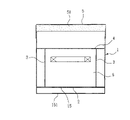
Fig. 4 is the section plan of the utility model structure.
The number in the figure explanation:
1 ... outer case
10 ... opening
11 ... antetheca
12 ... rear wall
13 ... sidewall
14 ... broken line
15 ... go up flexible plane materiel
151 ... following flexible plane materiel
16 ... the first adhesive buckle face
2 ... lower plate
3 ... location-plate
31 ... flap
32 ... the second adhesive buckle face
4 ... upper plate
5 ... lid
51 ... expanded material
6 ... storage box
61 ... antetheca
62 ... rear wall
63 ... sidewall
64 ... broken line
The specific embodiment
As Fig. 1 and shown in Figure 2, the chair type accommodation device that the utility model provides, its preferred technique means, include an outer case 1 and a storage box 6, the front of described outer case 1 is provided with an opening 10, it is interior to take in that storage box 6 can directly be pushed into outer case 1 from this opening 10, also can be drawn out to pick and place article from this opening; The top of outer case 1 then covers one can be as the lid 5 of seat.
Fig. 2 and shown in Figure 3 for another example, outer case 1 preferred embodiment of the present utility model, be utilize flexible cloth coat several plates the more fixing group of sewing structure form, make whole outer case 1 have an antetheca 11, connect the two side 13 of this antetheca 11, an and rear wall 12 that connects this two side 13, sidewall 13 wherein further coats two independently plates, connects with flexible cloth between two plates and constitutes a vertical broken line 14, makes sidewall 13 to fold; This antetheca 11, rear wall 12 and two side 13 following is connected one jointly and lays respectively at top and the last flexible plane materiel 15 of below and flexible plane materiel 151 once, and should go up flexible plane materiel 15 and have a distance between the flexible plane materiel 151 down, and by this apart from constituting a cushion space, and one case mouth of the common formation in the top of antetheca 11, rear wall 12 and two side 13 is provided with an opening 10 at antetheca 11 in addition.In order to make outer case 1 have sufficient intensity as seat, and allow storage box 6 can pass in and out outer case 1 swimmingly relatively, the utility model also 10 both sides of the opening in outer case 1 is provided with the location-plate 3 of two settings, by the arrangement for guiding of this two location-plate 3 as these opening 10 both sides, the while is as the reinforced structure of outer case 1.
Fig. 3 shows the combining structure of location-plate 3 of the present utility model and outer case 1 simultaneously, be to be respectively equipped with one first adhesive buckle face 16 with the medial surface of corresponding described rear wall 12 at antetheca 11 medial surfaces of opening 10 both sides of outer case 1, and two vertical edges of described two location-plates 3 are connected with a flap 31 respectively, the lateral surface of this flap 31 then is provided with the second adhesive buckle face 32 that can bind with this first adhesive buckle face 16, with the bonding of this second adhesive buckle face 32 this two location-plate 3 is fixed in described opening 10 both sides in this outer case 1 by this first adhesive buckle face 16.Before location-plate 3 is fixed in outer case 1, the utility model is preferably put into the lower plate 2 of a hard on the last flexible plane materiel 15 of outer case 1 earlier, and then location-plate 3 is fixed in outer case 1 with aforementioned manner, location-plate 3 is positioned on the lower plate 2, and then the upper plate 4 of a hard is placed in above the location-plate 3, again lid 5 is covered in outer case 1 top at last.
Consult Fig. 5, in order to make seat more comfortable, lid 5 of the present utility model can adopt soft plane materiel as extexine, and at extexine inner filling expanded material 51 or flexible material.
The same structure that shows storage box 6 of the present utility model of Fig. 3, also be utilize flexible cloth coat several plates the more fixing group of sewing structure form, a rear wall 62 that makes whole storage box 6 have an antetheca 61, connect the two side 63 of this antetheca 61 and connect this two side 63, sidewall 63 wherein further coats two independently plates, connect with flexible cloth between two plates and constitute a vertical broken line 64, make sidewall 63 to fold; The outside of antetheca can the sewing handle, so that the user pulls out storage box 6 from outer case 1.
By the aforesaid structure of the utility model, when the user is seated at the lid 5 of outer case 1 top, though most weight can be supported by outer case 1 and location-plate 3, block but storage box 6 still may be subjected to the effect of body weight for humans power and can't enter outer case smoothly, therefore, the utility model provides cushion space (as Fig. 2 and shown in Figure 4) by the space between the last flexible plane materiel 15 of being located at outer case 1 bottom and the following flexible plane materiel 151, can descend slightly after making flexible plane materiel 15 and lower plate 2 stressed, be avoided storage box 6 jammed problems.
The above, it only is preferred embodiment of the present utility model, be not that the utility model is done any pro forma restriction, every foundation technical spirit of the present utility model all still belongs in the scope of technical solutions of the utility model any simple modification, equivalent variations and modification that above embodiment did.
Claims (2)
1. a chair type accommodation device is characterized in that, comprising:
One outer case, a rear wall that has an antetheca, connects the two side of this antetheca and connect this two side, this antetheca, rear wall and two side following is connected on one flexible plane materiel and flexible plane materiel once jointly, and should go up flexible plane materiel and have a distance between the flexible plane materiel down, one case mouth of the common formation in the top of this antetheca, rear wall and two side, this antetheca is provided with an opening, and the antetheca medial surface of these opening both sides is respectively equipped with one first adhesive buckle face with the medial surface of corresponding described rear wall;
One lower plate places above the last flexible plane materiel of described outer case;
Two location-plates, the second adhesive buckle face that two vertical edges of this location-plate are respectively equipped with and this first adhesive buckle face binds, by the bonding of this first adhesive buckle face and this second adhesive buckle face and this two location-plate is fixed in described opening both sides in this outer case, and be positioned at this above lower plate;
One upper plate, place described two location-plates above;
One lid is covered in the case mouth of described outer case;
One storage box is combined in this outer case from the opening of described outer case.
2. chair type accommodation device according to claim 1 is characterized in that: the top of described lid is soft top layer, and this soft top layer is to coat expanded material.
Priority Applications (1)
| Application Number | Priority Date | Filing Date | Title |
|---|---|---|---|
| CNU2008201442606U CN201346032Y (en) | 2008-12-10 | 2008-12-10 | Seat type storage device |
Applications Claiming Priority (1)
| Application Number | Priority Date | Filing Date | Title |
|---|---|---|---|
| CNU2008201442606U CN201346032Y (en) | 2008-12-10 | 2008-12-10 | Seat type storage device |
Publications (1)
| Publication Number | Publication Date |
|---|---|
| CN201346032Y true CN201346032Y (en) | 2009-11-18 |
Family
ID=41365514
Family Applications (1)
| Application Number | Title | Priority Date | Filing Date |
|---|---|---|---|
| CNU2008201442606U Expired - Fee Related CN201346032Y (en) | 2008-12-10 | 2008-12-10 | Seat type storage device |
Country Status (1)
| Country | Link |
|---|---|
| CN (1) | CN201346032Y (en) |
Cited By (2)
| Publication number | Priority date | Publication date | Assignee | Title |
|---|---|---|---|---|
| CN102525172A (en) * | 2011-12-20 | 2012-07-04 | 浙江工业大学 | Multi-functional combined low stool |
| CN104433406A (en) * | 2014-12-12 | 2015-03-25 | 无锡豪思纺织品有限公司 | Novel folding stool |
-
2008
- 2008-12-10 CN CNU2008201442606U patent/CN201346032Y/en not_active Expired - Fee Related
Cited By (2)
| Publication number | Priority date | Publication date | Assignee | Title |
|---|---|---|---|---|
| CN102525172A (en) * | 2011-12-20 | 2012-07-04 | 浙江工业大学 | Multi-functional combined low stool |
| CN104433406A (en) * | 2014-12-12 | 2015-03-25 | 无锡豪思纺织品有限公司 | Novel folding stool |
Similar Documents
| Publication | Publication Date | Title |
|---|---|---|
| CN202641540U (en) | Multifunctional automobile armrest box | |
| TWM365098U (en) | Foldable luggage | |
| CN201346032Y (en) | Seat type storage device | |
| CN201816521U (en) | Carriage seat capable of storing case | |
| CN107380077A (en) | The interim storage device of car carry-on articles | |
| CN209382509U (en) | A kind of storing case | |
| CN212500146U (en) | Multifunctional pedal storage box | |
| CN201710083U (en) | Multifunctional holding bag | |
| CN216290305U (en) | Portable solar charging bag | |
| CN202160823U (en) | Foldable bag | |
| CN2914776Y (en) | Folding collection box capable of being used as seat | |
| CN106901505A (en) | A kind of multifunctional combination tea table | |
| CN203662156U (en) | Multifunctional suitcase | |
| CN205098616U (en) | Foldable storage box | |
| CN201727000U (en) | Folded luggage case | |
| CN202842943U (en) | Folding storage stool | |
| CN103431669B (en) | A kind of Foldable accommodation stool and preparation technology thereof | |
| CN202135985U (en) | Foldable stool | |
| CN213949084U (en) | Convenient folding containing box | |
| CN206006326U (en) | A kind of flexible luggage case | |
| CN205625780U (en) | Multi -functional portable removes closestool | |
| CN205432501U (en) | Schoolbag | |
| CN213974893U (en) | Portable multi-functional teaching aid receiver | |
| CN205345593U (en) | Cloth art arrangement case | |
| CN209202377U (en) | A kind of Foldable accommodation stool shoe chest |
Legal Events
| Date | Code | Title | Description |
|---|---|---|---|
| C14 | Grant of patent or utility model | ||
| GR01 | Patent grant | ||
| CF01 | Termination of patent right due to non-payment of annual fee |
Granted publication date: 20091118 Termination date: 20141210 |
|
| EXPY | Termination of patent right or utility model |